ES2818627T3 - Laser welding method of a car light - Google Patents
Laser welding method of a car light Download PDFInfo
- Publication number
- ES2818627T3 ES2818627T3 ES15165724T ES15165724T ES2818627T3 ES 2818627 T3 ES2818627 T3 ES 2818627T3 ES 15165724 T ES15165724 T ES 15165724T ES 15165724 T ES15165724 T ES 15165724T ES 2818627 T3 ES2818627 T3 ES 2818627T3
- Authority
- ES
- Spain
- Prior art keywords
- interface
- critical portion
- lenticular body
- laser
- optical
- Prior art date
- Legal status (The legal status is an assumption and is not a legal conclusion. Google has not performed a legal analysis and makes no representation as to the accuracy of the status listed.)
- Active
Links
- 238000003466 welding Methods 0.000 title claims abstract description 80
- 238000000034 method Methods 0.000 title claims description 25
- 230000003287 optical effect Effects 0.000 claims abstract description 73
- 239000000835 fiber Substances 0.000 claims abstract description 40
- 238000004519 manufacturing process Methods 0.000 claims abstract description 25
- 230000005855 radiation Effects 0.000 claims abstract description 15
- 230000008859 change Effects 0.000 claims abstract description 11
- 238000000295 emission spectrum Methods 0.000 claims abstract description 4
- 239000007787 solid Substances 0.000 claims description 7
- 238000009826 distribution Methods 0.000 claims description 6
- 229910000679 solder Inorganic materials 0.000 claims description 5
- 230000009467 reduction Effects 0.000 claims description 3
- 239000012780 transparent material Substances 0.000 claims 1
- 239000011324 bead Substances 0.000 description 16
- 239000013307 optical fiber Substances 0.000 description 13
- 239000000463 material Substances 0.000 description 6
- 230000002745 absorbent Effects 0.000 description 4
- 239000002250 absorbent Substances 0.000 description 4
- 230000008569 process Effects 0.000 description 3
- 230000008878 coupling Effects 0.000 description 2
- 238000010168 coupling process Methods 0.000 description 2
- 238000005859 coupling reaction Methods 0.000 description 2
- 230000005670 electromagnetic radiation Effects 0.000 description 2
- 230000006870 function Effects 0.000 description 2
- 230000001788 irregular Effects 0.000 description 2
- 238000005304 joining Methods 0.000 description 2
- 229920000642 polymer Polymers 0.000 description 2
- 238000007789 sealing Methods 0.000 description 2
- 230000011664 signaling Effects 0.000 description 2
- 238000010521 absorption reaction Methods 0.000 description 1
- 230000001143 conditioned effect Effects 0.000 description 1
- 238000010276 construction Methods 0.000 description 1
- 239000013078 crystal Substances 0.000 description 1
- 230000001419 dependent effect Effects 0.000 description 1
- 230000005611 electricity Effects 0.000 description 1
- 230000004927 fusion Effects 0.000 description 1
- 238000010438 heat treatment Methods 0.000 description 1
- 230000003116 impacting effect Effects 0.000 description 1
- 239000011159 matrix material Substances 0.000 description 1
- 239000002184 metal Substances 0.000 description 1
- 239000000203 mixture Substances 0.000 description 1
- 238000012986 modification Methods 0.000 description 1
- 230000004048 modification Effects 0.000 description 1
- 238000003825 pressing Methods 0.000 description 1
- 239000004065 semiconductor Substances 0.000 description 1
- 230000009131 signaling function Effects 0.000 description 1
Classifications
-
- B—PERFORMING OPERATIONS; TRANSPORTING
- B29—WORKING OF PLASTICS; WORKING OF SUBSTANCES IN A PLASTIC STATE IN GENERAL
- B29C—SHAPING OR JOINING OF PLASTICS; SHAPING OF MATERIAL IN A PLASTIC STATE, NOT OTHERWISE PROVIDED FOR; AFTER-TREATMENT OF THE SHAPED PRODUCTS, e.g. REPAIRING
- B29C65/00—Joining or sealing of preformed parts, e.g. welding of plastics materials; Apparatus therefor
- B29C65/02—Joining or sealing of preformed parts, e.g. welding of plastics materials; Apparatus therefor by heating, with or without pressure
- B29C65/14—Joining or sealing of preformed parts, e.g. welding of plastics materials; Apparatus therefor by heating, with or without pressure using wave energy, i.e. electromagnetic radiation, or particle radiation
- B29C65/16—Laser beams
- B29C65/1629—Laser beams characterised by the way of heating the interface
- B29C65/1635—Laser beams characterised by the way of heating the interface at least passing through one of the parts to be joined, i.e. laser transmission welding
- B29C65/1638—Laser beams characterised by the way of heating the interface at least passing through one of the parts to be joined, i.e. laser transmission welding focusing the laser beam on the interface
-
- B—PERFORMING OPERATIONS; TRANSPORTING
- B29—WORKING OF PLASTICS; WORKING OF SUBSTANCES IN A PLASTIC STATE IN GENERAL
- B29C—SHAPING OR JOINING OF PLASTICS; SHAPING OF MATERIAL IN A PLASTIC STATE, NOT OTHERWISE PROVIDED FOR; AFTER-TREATMENT OF THE SHAPED PRODUCTS, e.g. REPAIRING
- B29C65/00—Joining or sealing of preformed parts, e.g. welding of plastics materials; Apparatus therefor
- B29C65/02—Joining or sealing of preformed parts, e.g. welding of plastics materials; Apparatus therefor by heating, with or without pressure
- B29C65/14—Joining or sealing of preformed parts, e.g. welding of plastics materials; Apparatus therefor by heating, with or without pressure using wave energy, i.e. electromagnetic radiation, or particle radiation
- B29C65/16—Laser beams
- B29C65/1629—Laser beams characterised by the way of heating the interface
- B29C65/1635—Laser beams characterised by the way of heating the interface at least passing through one of the parts to be joined, i.e. laser transmission welding
-
- B—PERFORMING OPERATIONS; TRANSPORTING
- B23—MACHINE TOOLS; METAL-WORKING NOT OTHERWISE PROVIDED FOR
- B23K—SOLDERING OR UNSOLDERING; WELDING; CLADDING OR PLATING BY SOLDERING OR WELDING; CUTTING BY APPLYING HEAT LOCALLY, e.g. FLAME CUTTING; WORKING BY LASER BEAM
- B23K26/00—Working by laser beam, e.g. welding, cutting or boring
- B23K26/20—Bonding
-
- B—PERFORMING OPERATIONS; TRANSPORTING
- B29—WORKING OF PLASTICS; WORKING OF SUBSTANCES IN A PLASTIC STATE IN GENERAL
- B29C—SHAPING OR JOINING OF PLASTICS; SHAPING OF MATERIAL IN A PLASTIC STATE, NOT OTHERWISE PROVIDED FOR; AFTER-TREATMENT OF THE SHAPED PRODUCTS, e.g. REPAIRING
- B29C65/00—Joining or sealing of preformed parts, e.g. welding of plastics materials; Apparatus therefor
- B29C65/02—Joining or sealing of preformed parts, e.g. welding of plastics materials; Apparatus therefor by heating, with or without pressure
- B29C65/14—Joining or sealing of preformed parts, e.g. welding of plastics materials; Apparatus therefor by heating, with or without pressure using wave energy, i.e. electromagnetic radiation, or particle radiation
- B29C65/16—Laser beams
- B29C65/1629—Laser beams characterised by the way of heating the interface
- B29C65/1664—Laser beams characterised by the way of heating the interface making use of several radiators
- B29C65/1667—Laser beams characterised by the way of heating the interface making use of several radiators at the same time, i.e. simultaneous laser welding
- B29C65/167—Laser beams characterised by the way of heating the interface making use of several radiators at the same time, i.e. simultaneous laser welding using laser diodes
-
- B—PERFORMING OPERATIONS; TRANSPORTING
- B29—WORKING OF PLASTICS; WORKING OF SUBSTANCES IN A PLASTIC STATE IN GENERAL
- B29C—SHAPING OR JOINING OF PLASTICS; SHAPING OF MATERIAL IN A PLASTIC STATE, NOT OTHERWISE PROVIDED FOR; AFTER-TREATMENT OF THE SHAPED PRODUCTS, e.g. REPAIRING
- B29C65/00—Joining or sealing of preformed parts, e.g. welding of plastics materials; Apparatus therefor
- B29C65/02—Joining or sealing of preformed parts, e.g. welding of plastics materials; Apparatus therefor by heating, with or without pressure
- B29C65/14—Joining or sealing of preformed parts, e.g. welding of plastics materials; Apparatus therefor by heating, with or without pressure using wave energy, i.e. electromagnetic radiation, or particle radiation
- B29C65/16—Laser beams
- B29C65/1687—Laser beams making use of light guides
-
- B—PERFORMING OPERATIONS; TRANSPORTING
- B29—WORKING OF PLASTICS; WORKING OF SUBSTANCES IN A PLASTIC STATE IN GENERAL
- B29C—SHAPING OR JOINING OF PLASTICS; SHAPING OF MATERIAL IN A PLASTIC STATE, NOT OTHERWISE PROVIDED FOR; AFTER-TREATMENT OF THE SHAPED PRODUCTS, e.g. REPAIRING
- B29C65/00—Joining or sealing of preformed parts, e.g. welding of plastics materials; Apparatus therefor
- B29C65/02—Joining or sealing of preformed parts, e.g. welding of plastics materials; Apparatus therefor by heating, with or without pressure
- B29C65/14—Joining or sealing of preformed parts, e.g. welding of plastics materials; Apparatus therefor by heating, with or without pressure using wave energy, i.e. electromagnetic radiation, or particle radiation
- B29C65/16—Laser beams
- B29C65/1696—Laser beams making use of masks
-
- B—PERFORMING OPERATIONS; TRANSPORTING
- B29—WORKING OF PLASTICS; WORKING OF SUBSTANCES IN A PLASTIC STATE IN GENERAL
- B29C—SHAPING OR JOINING OF PLASTICS; SHAPING OF MATERIAL IN A PLASTIC STATE, NOT OTHERWISE PROVIDED FOR; AFTER-TREATMENT OF THE SHAPED PRODUCTS, e.g. REPAIRING
- B29C66/00—General aspects of processes or apparatus for joining preformed parts
- B29C66/01—General aspects dealing with the joint area or with the area to be joined
- B29C66/05—Particular design of joint configurations
- B29C66/10—Particular design of joint configurations particular design of the joint cross-sections
- B29C66/11—Joint cross-sections comprising a single joint-segment, i.e. one of the parts to be joined comprising a single joint-segment in the joint cross-section
- B29C66/114—Single butt joints
-
- B—PERFORMING OPERATIONS; TRANSPORTING
- B29—WORKING OF PLASTICS; WORKING OF SUBSTANCES IN A PLASTIC STATE IN GENERAL
- B29C—SHAPING OR JOINING OF PLASTICS; SHAPING OF MATERIAL IN A PLASTIC STATE, NOT OTHERWISE PROVIDED FOR; AFTER-TREATMENT OF THE SHAPED PRODUCTS, e.g. REPAIRING
- B29C66/00—General aspects of processes or apparatus for joining preformed parts
- B29C66/01—General aspects dealing with the joint area or with the area to be joined
- B29C66/05—Particular design of joint configurations
- B29C66/10—Particular design of joint configurations particular design of the joint cross-sections
- B29C66/13—Single flanged joints; Fin-type joints; Single hem joints; Edge joints; Interpenetrating fingered joints; Other specific particular designs of joint cross-sections not provided for in groups B29C66/11 - B29C66/12
- B29C66/131—Single flanged joints, i.e. one of the parts to be joined being rigid and flanged in the joint area
-
- B—PERFORMING OPERATIONS; TRANSPORTING
- B29—WORKING OF PLASTICS; WORKING OF SUBSTANCES IN A PLASTIC STATE IN GENERAL
- B29C—SHAPING OR JOINING OF PLASTICS; SHAPING OF MATERIAL IN A PLASTIC STATE, NOT OTHERWISE PROVIDED FOR; AFTER-TREATMENT OF THE SHAPED PRODUCTS, e.g. REPAIRING
- B29C66/00—General aspects of processes or apparatus for joining preformed parts
- B29C66/01—General aspects dealing with the joint area or with the area to be joined
- B29C66/05—Particular design of joint configurations
- B29C66/20—Particular design of joint configurations particular design of the joint lines, e.g. of the weld lines
- B29C66/24—Particular design of joint configurations particular design of the joint lines, e.g. of the weld lines said joint lines being closed or non-straight
- B29C66/242—Particular design of joint configurations particular design of the joint lines, e.g. of the weld lines said joint lines being closed or non-straight said joint lines being closed, i.e. forming closed contours
- B29C66/2424—Particular design of joint configurations particular design of the joint lines, e.g. of the weld lines said joint lines being closed or non-straight said joint lines being closed, i.e. forming closed contours being a closed polygonal chain
- B29C66/24243—Particular design of joint configurations particular design of the joint lines, e.g. of the weld lines said joint lines being closed or non-straight said joint lines being closed, i.e. forming closed contours being a closed polygonal chain forming a quadrilateral
- B29C66/24244—Particular design of joint configurations particular design of the joint lines, e.g. of the weld lines said joint lines being closed or non-straight said joint lines being closed, i.e. forming closed contours being a closed polygonal chain forming a quadrilateral forming a rectangle
-
- B—PERFORMING OPERATIONS; TRANSPORTING
- B29—WORKING OF PLASTICS; WORKING OF SUBSTANCES IN A PLASTIC STATE IN GENERAL
- B29C—SHAPING OR JOINING OF PLASTICS; SHAPING OF MATERIAL IN A PLASTIC STATE, NOT OTHERWISE PROVIDED FOR; AFTER-TREATMENT OF THE SHAPED PRODUCTS, e.g. REPAIRING
- B29C66/00—General aspects of processes or apparatus for joining preformed parts
- B29C66/50—General aspects of joining tubular articles; General aspects of joining long products, i.e. bars or profiled elements; General aspects of joining single elements to tubular articles, hollow articles or bars; General aspects of joining several hollow-preforms to form hollow or tubular articles
- B29C66/51—Joining tubular articles, profiled elements or bars; Joining single elements to tubular articles, hollow articles or bars; Joining several hollow-preforms to form hollow or tubular articles
- B29C66/54—Joining several hollow-preforms, e.g. half-shells, to form hollow articles, e.g. for making balls, containers; Joining several hollow-preforms, e.g. half-cylinders, to form tubular articles
- B29C66/542—Joining several hollow-preforms, e.g. half-shells, to form hollow articles, e.g. for making balls, containers; Joining several hollow-preforms, e.g. half-cylinders, to form tubular articles joining hollow covers or hollow bottoms to open ends of container bodies
-
- B—PERFORMING OPERATIONS; TRANSPORTING
- B29—WORKING OF PLASTICS; WORKING OF SUBSTANCES IN A PLASTIC STATE IN GENERAL
- B29C—SHAPING OR JOINING OF PLASTICS; SHAPING OF MATERIAL IN A PLASTIC STATE, NOT OTHERWISE PROVIDED FOR; AFTER-TREATMENT OF THE SHAPED PRODUCTS, e.g. REPAIRING
- B29C66/00—General aspects of processes or apparatus for joining preformed parts
- B29C66/90—Measuring or controlling the joining process
- B29C66/95—Measuring or controlling the joining process by measuring or controlling specific variables not covered by groups B29C66/91 - B29C66/94
- B29C66/959—Measuring or controlling the joining process by measuring or controlling specific variables not covered by groups B29C66/91 - B29C66/94 characterised by specific values or ranges of said specific variables
- B29C66/9592—Measuring or controlling the joining process by measuring or controlling specific variables not covered by groups B29C66/91 - B29C66/94 characterised by specific values or ranges of said specific variables in explicit relation to another variable, e.g. X-Y diagrams
-
- B—PERFORMING OPERATIONS; TRANSPORTING
- B29—WORKING OF PLASTICS; WORKING OF SUBSTANCES IN A PLASTIC STATE IN GENERAL
- B29C—SHAPING OR JOINING OF PLASTICS; SHAPING OF MATERIAL IN A PLASTIC STATE, NOT OTHERWISE PROVIDED FOR; AFTER-TREATMENT OF THE SHAPED PRODUCTS, e.g. REPAIRING
- B29C65/00—Joining or sealing of preformed parts, e.g. welding of plastics materials; Apparatus therefor
- B29C65/02—Joining or sealing of preformed parts, e.g. welding of plastics materials; Apparatus therefor by heating, with or without pressure
- B29C65/14—Joining or sealing of preformed parts, e.g. welding of plastics materials; Apparatus therefor by heating, with or without pressure using wave energy, i.e. electromagnetic radiation, or particle radiation
- B29C65/16—Laser beams
- B29C65/1629—Laser beams characterised by the way of heating the interface
- B29C65/1654—Laser beams characterised by the way of heating the interface scanning at least one of the parts to be joined
- B29C65/1661—Laser beams characterised by the way of heating the interface scanning at least one of the parts to be joined scanning repeatedly, e.g. quasi-simultaneous laser welding
-
- B—PERFORMING OPERATIONS; TRANSPORTING
- B29—WORKING OF PLASTICS; WORKING OF SUBSTANCES IN A PLASTIC STATE IN GENERAL
- B29L—INDEXING SCHEME ASSOCIATED WITH SUBCLASS B29C, RELATING TO PARTICULAR ARTICLES
- B29L2031/00—Other particular articles
- B29L2031/747—Lightning equipment
-
- F—MECHANICAL ENGINEERING; LIGHTING; HEATING; WEAPONS; BLASTING
- F21—LIGHTING
- F21S—NON-PORTABLE LIGHTING DEVICES; SYSTEMS THEREOF; VEHICLE LIGHTING DEVICES SPECIALLY ADAPTED FOR VEHICLE EXTERIORS
- F21S41/00—Illuminating devices specially adapted for vehicle exteriors, e.g. headlamps
- F21S41/20—Illuminating devices specially adapted for vehicle exteriors, e.g. headlamps characterised by refractors, transparent cover plates, light guides or filters
- F21S41/28—Cover glass
-
- F—MECHANICAL ENGINEERING; LIGHTING; HEATING; WEAPONS; BLASTING
- F21—LIGHTING
- F21S—NON-PORTABLE LIGHTING DEVICES; SYSTEMS THEREOF; VEHICLE LIGHTING DEVICES SPECIALLY ADAPTED FOR VEHICLE EXTERIORS
- F21S41/00—Illuminating devices specially adapted for vehicle exteriors, e.g. headlamps
- F21S41/20—Illuminating devices specially adapted for vehicle exteriors, e.g. headlamps characterised by refractors, transparent cover plates, light guides or filters
- F21S41/29—Attachment thereof
-
- F—MECHANICAL ENGINEERING; LIGHTING; HEATING; WEAPONS; BLASTING
- F21—LIGHTING
- F21S—NON-PORTABLE LIGHTING DEVICES; SYSTEMS THEREOF; VEHICLE LIGHTING DEVICES SPECIALLY ADAPTED FOR VEHICLE EXTERIORS
- F21S43/00—Signalling devices specially adapted for vehicle exteriors, e.g. brake lamps, direction indicator lights or reversing lights
- F21S43/20—Signalling devices specially adapted for vehicle exteriors, e.g. brake lamps, direction indicator lights or reversing lights characterised by refractors, transparent cover plates, light guides or filters
- F21S43/27—Attachment thereof
Landscapes
- Physics & Mathematics (AREA)
- Engineering & Computer Science (AREA)
- Optics & Photonics (AREA)
- Mechanical Engineering (AREA)
- Health & Medical Sciences (AREA)
- Electromagnetism (AREA)
- Toxicology (AREA)
- Microelectronics & Electronic Packaging (AREA)
- Plasma & Fusion (AREA)
- Laser Beam Processing (AREA)
- Lining Or Joining Of Plastics Or The Like (AREA)
- Manufacturing & Machinery (AREA)
- Non-Portable Lighting Devices Or Systems Thereof (AREA)
- Chemical & Material Sciences (AREA)
- Combustion & Propulsion (AREA)
- Transportation (AREA)
- General Engineering & Computer Science (AREA)
Abstract
Método de fabricación de una luz (4) de automóvil que comprende los pasos de: - proporcionar un cuerpo (8) de contenedor delimitado por un primer perfil perimetral (20), - proporcionar un cuerpo lenticular (24), delimitado interiormente por un segundo perfil perimetral (28) y exteriormente por un borde exterior (32) correspondiente a dicho segundo perfil perimetral (28), - asociar mutuamente al menos parcialmente los respectivos perfiles perimetrales primero y segundo (20, 28) del cuerpo (8) de contenedor y del cuerpo lenticular (24), definiendo la superficie de contacto entre dichos perfiles perimetrales (20, 28) una interfaz (48) de soldadura que se extiende a lo largo de una curva definida por una abscisa curvilínea (S), - proporcionar al menos un dispositivo emisor de láser que emite un haz de luz o radiación con un espectro de emisión característico, caracterizado porque comprende los pasos de: - proporcionar una pluralidad de fibras (44) que reciben porciones del haz de láser del dispositivo emisor de láser y las dirigen hacia la interfaz (36) de soldadura a través del cuerpo lenticular (24), en el que el cuerpo (8) de contenedor actúa como elemento absorbente hacia el haz de luz y el cuerpo lenticular (24) actúa como elemento transmisor del haz de luz, - proporcionar dispositivos ópticos (52) para cambiar la divergencia de las porciones de haces de láser que salen de las fibras (44), para colimarlas en general a lo largo de al menos un eje óptico predeterminado (X-X), - identificar al menos una discontinuidad (54) en el borde exterior (32) del cuerpo lenticular (24), - dirigir sobre una porción crítica (64) de la interfaz (36) de soldadura al menos un primer haz (60) de láser emitido por una fibra respectiva (44) que se encuentra en un plano óptico (P) incidente con dicha porción crítica (64) de la interfaz (36) de soldadura, - en el que dicha porción crítica (64) es la porción de interfaz (36) de soldadura correspondiente, por ejemplo, alineada, en una dirección perpendicular a dicha interfaz (36) de soladura, con dicha discontinuidad (54), - en el que dicha discontinuidad (54) constituye un cambio en la distancia (55) entre el borde exterior (32) y la interfaz (36) de soldadura, - en el que el plano óptico (P) identifica un ángulo de orientación (α 0 y 45 grados con un plano (T) tangente a 40 la porción crítica (64) de la interfaz (36) de soldadura.Manufacturing method of a car light (4) comprising the steps of: - providing a container body (8) delimited by a first perimeter profile (20), - providing a lenticular body (24), internally delimited by a second perimeter profile (28) and externally by an outer edge (32) corresponding to said second perimeter profile (28), - mutually at least partially associate the respective first and second perimeter profiles (20, 28) of the container body (8) and of the lenticular body (24), the contact surface between said perimeter profiles (20, 28) defining a welding interface (48) that extends along a curve defined by a curvilinear abscissa (S), - providing at least a laser emitting device that emits a beam of light or radiation with a characteristic emission spectrum, characterized in that it comprises the steps of: - providing a plurality of fibers (44) that receive portions of the laser beam from the laser emitting device and direct them towards the welding interface (36) through the lenticular body (24), in which the container body (8) acts as an absorbing element towards the light beam and the lenticular body (24) acts as a transmitting element of the light beam, - providing optical devices (52) to change the divergence of the portions of laser beams exiting the fibers (44), to collimate them generally along at least one predetermined optical axis (XX), - identifying at least one discontinuity (54) in the outer edge (32) of the lenticular body (24), - directing on a critical portion (64) of the welding interface (36) at least one first beam ( 60) of laser emitted by a respective fiber (44) that lies in an optical plane (P) incident with said critical portion (64) of the welding interface (36), - wherein said critical portion (64) is the corresponding weld interface portion (36), for example aligned, in one direction perpendicular to said weld interface (36), with said discontinuity (54), - wherein said discontinuity (54) constitutes a change in the distance (55) between the outer edge (32) and the interface (36) of welding, - in which the optical plane (P) identifies an orientation angle (α 0 and 45 degrees with a plane (T) tangent to the critical portion (64) of the welding interface (36).
Description
DESCRIPCIÓNDESCRIPTION
Método de soldadura de láser de una luz de automóvilLaser welding method of a car light
Campo de aplicaciónScope
La presente invención se refiere a un método de soldadura de láser de una luz de automóvil.The present invention relates to a method of laser welding an automobile light.
Estado de la técnicaState of the art
El término luz de automóvil se entiende que significa indistintamente una luz de automóvil trasera o una luz de automóvil delantera, esta última también conocida como faro delantero.The term automobile light is understood to mean indistinctly a rear automobile light or a front automobile light, the latter also known as a headlight.
Como es conocido, una luz de automóvil es un dispositivo de iluminación y/o señalización de un vehículo que comprende al menos una luz de automóvil externa que tiene una función de iluminación y/o señalización hacia el exterior del vehículo tales como una luz lateral, una luz indicadora, una luz de freno, una luz antiniebla trasera, una luz de marcha atrás, una luz de cruce, una luz de carretera y similares.As is known, a car light is a vehicle lighting and / or signaling device comprising at least one external car light that has a function of lighting and / or signaling towards the outside of the vehicle such as a side light, an indicator light, a brake light, a rear fog light, a reversing light, a low beam, a high beam and the like.
La luz de automóvil, en su forma más simple, comprende un cuerpo de contenedor, un cuerpo lenticular y al menos una fuente de luz.Automobile light, in its simplest form, comprises a container body, a lenticular body, and at least one light source.
El cuerpo lenticular se coloca para cerrar una boca del cuerpo de contenedor para formar una cámara de alojamiento. La fuente de luz está dispuesta dentro de la cámara de alojamiento, que puede ser dirigida para emitir luz hacia el cuerpo lenticular, cuando se alimenta con electricidad.The lenticular body is positioned to close a mouth of the container body to form a housing chamber. The light source is arranged within the housing chamber, which can be directed to emit light towards the lenticular body, when supplied with electricity.
El método de fabricación de una luz de automóvil, una vez ensamblados los diversos componentes, debe proporcionar la fijación y sellado hermético del cuerpo lenticular al cuerpo de contenedor.The method of manufacturing an automobile light, once the various components are assembled, must provide for the attachment and hermetic sealing of the lenticular body to the container body.
Tal sellado y fijación se realiza habitualmente mediante soldadura para crear un cordón de soldadura entre los perfiles perimetrales, respectivamente, del cuerpo lenticular y el cuerpo de contenedor colocados en contacto entre sí.Such sealing and fixing is usually done by welding to create a weld bead between the perimeter profiles, respectively, of the lenticular body and the container body placed in contact with each other.
Naturalmente, la soldadura también puede afectar a otros componentes de una luz de automóvil más compleja, por ejemplo, dispuestos dentro de la cámara de alojamiento.Of course, welding can also affect other components of a more complex car light, for example arranged within the housing chamber.
Un proceso de soldadura de láser de cuerpos poliméricos, en particular de una luz de automóvil, hace que se combine un cuerpo polimérico transmisor, capaz de transmitir una radiación de láser, y un cuerpo polimérico absorbente, capaz de absorber la radiación de láser. En el presente caso, la radiación de láser se transforma en calor cuando se encuentra con el cuerpo polimérico absorbente, cuyo calentamiento transfiere localmente el calor al cuerpo polimérico transmisor, en la medida de un ablandamiento y una fusión local de ambos cuerpos poliméricos, que se unen así firmemente entre sí.A process of laser welding of polymeric bodies, in particular of an automobile light, combines a transmitting polymeric body, capable of transmitting laser radiation, and an absorbent polymeric body, capable of absorbing laser radiation. In the present case, the laser radiation is transformed into heat when it encounters the absorbent polymeric body, the heating of which locally transfers the heat to the transmitting polymeric body, to the extent of a local softening and fusion of both polymeric bodies, which are thus firmly attached to each other.
El cuerpo polimérico absorbente de una luz de automóvil puede estar constituido, por ejemplo, por el cuerpo de contenedor, mientras que el cuerpo polimérico transmisor de una luz de automóvil puede estar constituido, por ejemplo, por el cuerpo lenticular, que al cerrar el cuerpo de contenedor forma una cámara de alojamiento que aloja una fuente de luz del faro delantero de automóvil.The absorbent polymeric body of a car light can be constituted, for example, by the container body, while the transmitting polymeric body of a car light can be constituted, for example, by the lenticular body, which when closing the body The container forms a housing chamber that houses a light source for the automobile headlight.
Tal cámara de alojamiento está delimitada en el perímetro por los perfiles perimetrales del cuerpo de contenedor y del cuerpo lenticular que, colocados en contacto entre sí, se sellan mediante la formación de un cordón de soldadura, en el que la interpenetración de los materiales del cuerpo lenticular y el cuerpo de contenedor tiene lugar. Por supuesto, los cuerpos poliméricos absorbentes y transmisores pueden estar compuestos genéricamente de otros componentes poliméricos del faro delantero de automóvil.Such a housing chamber is delimited on the perimeter by the perimeter profiles of the container body and the lenticular body which, placed in contact with each other, are sealed by forming a weld bead, in which the interpenetration of the materials of the body lenticular and container body takes place. Of course, the absorbent and transmitting polymeric bodies can be generally composed of other polymeric components of the automobile headlight.
En cuanto al equipo de láser que se usará, generalmente comprende:As for the laser equipment to be used, it generally comprises:
- al menos una fuente de láser, que puede ser, por ejemplo, una fuente de láser semiconductora,- at least one laser source, which can be, for example, a semiconductor laser source,
- un sistema de fibras ópticas agrupadas en un "manojo" que sirve para transportar la luz de láser producida por la fuente de láser, en las proximidades del cuerpo lenticular,- a system of optical fibers grouped in a "bundle" that serves to transport the laser light produced by the laser source, in the vicinity of the lenticular body,
- un soporte de fibra óptica que tiene por objeto mantener las fibras ópticas en su posición en las proximidades del cuerpo lenticular. Por ejemplo, el soporte puede ser un cuerpo metálico con agujeros de alojamiento en los que están contenidas las fibras ópticas. Pueden fijarse mediante un sistema en el que la cabeza de un tornillo, que se atornilla al soporte metálico de las fibras ópticas, presiona una arandela de polímero que se expande radialmente. La fibra óptica queda así bloqueada por la arandela de polímero en las paredes del agujero del alojamiento, - a fiber optic support whose object is to keep the optical fibers in their position in the vicinity of the lenticular body. For example, the support can be a metal body with housing holes in which the optical fibers are contained. They can be fixed by a system in which the head of a screw, which is screwed to the metallic support of the optical fibers, presses a polymer washer that expands radially. The optical fiber is thus blocked by the polymer washer on the walls of the housing hole,
- un sistema óptico, con la función de un colimador, que tiene como finalidad modificar la divergencia del haz de láser que sale de la fibra y dirigir dicho haz hacia el cordón de soldadura.- an optical system, with the function of a collimator, the purpose of which is to modify the divergence of the laser beam coming out of the fiber and directing said beam towards the weld bead.
Típicamente, como un colimador, se usa una guía de luz negativa, es decir, una guía de luz formada por paredes reflectantes inclinadas con respecto al eje óptico de la fibra.Typically, as a collimator, a negative light guide is used, that is, a light guide formed by reflective walls inclined with respect to the optical axis of the fiber.
En la versión más simple de la técnica anterior (figura 1), la guía de luz tiene una geometría con paredes reflectantes inclinadas con respecto a su eje óptico y la fibra óptica se posiciona en las proximidades de la abertura superior de la guía de luz y a lo largo del eje óptico. De nuevo, en el caso más simple, el sistema demuestra ser simétrico en el plano transversal de la guía de luz, es decir, la inclinación de las paredes reflectantes de la guía de luz es la misma con respecto al eje óptico. Longitudinalmente, la guía de luz se extiende a lo largo de la trayectoria que define el cordón de soldadura.In the simplest version of the prior art (figure 1), the light guide has a geometry with reflective walls inclined with respect to its optical axis and the optical fiber is positioned in the vicinity of the upper opening of the light guide already along the optic axis. Again, in the simplest case, the system proves to be symmetrical in the transverse plane of the light guide, that is, the inclination of the reflective walls of the light guide is the same with respect to the optical axis. Longitudinally, the light guide extends along the path that defines the weld bead.
Un parámetro que está relacionado con la distribución de las fibras ópticas a lo largo de la trayectoria del cordón de soldadura es la distancia o paso 'd' entre las fibras, cuyo valor mínimo viene dado por las dimensiones de las fibras ópticas y del sistema de fijación y cuyo valor máximo está condicionado por el valor mínimo de energía depositada en el cordón.A parameter that is related to the distribution of the optical fibers along the path of the weld bead is the distance or pitch 'd' between the fibers, whose minimum value is given by the dimensions of the optical fibers and the system of fixation and whose maximum value is conditioned by the minimum value of energy deposited in the cord.
Esta configuración se usa generalmente cuando el sistema, es decir, la luz a soldar, tiene una geometría simple. Cuando sea necesario aumentar la energía de radiación depositada en el cordón de soldadura, por ejemplo, cuando el grosor del cuerpo lenticular es elevado con el consiguiente aumento de la absorción por el material, se pueden usar dos filas de fibras ópticas en la misma guía de luz (figuras 2-3). Las fibras ópticas pueden estar dispuestas en un mismo plano transversal (figura 2) o en diferentes planos transversales (figura 3).This configuration is generally used when the system, that is, the light to be welded, has a simple geometry. When it is necessary to increase the radiation energy deposited in the weld bead, for example, when the thickness of the lenticular body is high with the consequent increase in absorption by the material, two rows of optical fibers can be used in the same guide of light (Figures 2-3). Optical fibers can be arranged in the same transverse plane (figure 2) or in different transverse planes (figure 3).
En el primer caso, las fibras ópticas pertenecientes a un mismo plano transversal apuntan a la misma región del cordón de soldadura.In the first case, the optical fibers belonging to the same transverse plane point to the same region of the weld bead.
En el segundo caso, las fibras ópticas, situadas en diferentes planos, apuntan a distintas áreas del cordón de soldadura con el objetivo de hacer más uniforme la irradiación.In the second case, the optical fibers, located in different planes, point to different areas of the weld bead in order to make the irradiation more uniform.
Sin embargo, el cuerpo lenticular puede tener una geometría compleja por motivos estilísticos y aerodinámicos. Debido a esto, el cordón de soldadura resulta no conforme con el cuerpo lenticular, es decir, puede que no sea una traslación del cuerpo lenticular. Sin embargo, debe garantizarse una irradiación continua y homogénea a lo largo del cordón de soldadura incluso si el cuerpo lenticular tiene una superficie irregular.However, the lenticular body can have a complex geometry for stylistic and aerodynamic reasons. Because of this, the weld bead becomes non-conforming to the lenticular body, that is, it may not be a translation of the lenticular body. However, a continuous and homogeneous irradiation along the weld bead must be ensured even if the lenticular body has an uneven surface.
Con las soluciones de la técnica anterior, es decir, con la configuración en la que las fibras están inclinadas con respecto al eje óptico en un plano transversal al cordón de soldadura, se crea una irradiación no uniforme debido a la presencia de zonas de sombra. En la figura 4 se ha resaltado la presencia de una zona de sombra en la irradiación del cordón de soldadura en áreas con geometrías complejas o áreas irregulares del cuerpo lenticular. La misma figura 4 muestra también cómo, gracias a la presente invención, es posible rellenar dicha zona de sombra para obtener una soldadura uniforme y regular, como se describe mejor a continuación. Tales soluciones se describen, por ejemplo, en los documentos JP 2013 196891 A, US 2012/241424 A1, JP 2014061639 y FR 2952316 A1.With the solutions of the prior art, that is, with the configuration in which the fibers are inclined with respect to the optical axis in a plane transverse to the weld bead, a non-uniform irradiation is created due to the presence of shadow areas. Figure 4 highlights the presence of a shadow area in the irradiation of the weld bead in areas with complex geometries or irregular areas of the lenticular body. The same figure 4 also shows how, thanks to the present invention, it is possible to fill in said shadow area to obtain a uniform and regular weld, as is better described below. Such solutions are described, for example, in documents JP 2013 196891 A, US 2012/241424 A1, JP 2014061639 and FR 2952316 A1.
De ello se deduce que, en el caso de la soldadura de luces de automóvil donde el cuerpo lenticular habitualmente tiene geometrías complejas (tales como variaciones de concavidades/complejidad, ranuras, nervaduras, protuberancias, etc.), las soluciones de la técnica anterior de soldadura de láser no son satisfactorias en términos de calidad del cordón de soldadura generado.It follows that, in the case of automotive headlight welding where the lenticular body typically has complex geometries (such as concavity / complexity variations, grooves, ribs, protrusions, etc.), prior art solutions of laser welding are not satisfactory in terms of the quality of the weld bead generated.
A la luz de todas las consideraciones anteriores, las técnicas de soldadura de láser se usan poco hasta la fecha en las luces de automóvil, especialmente si tienen una geometría compleja; por tanto, tales técnicas de soldadura de láser son reemplazadas por técnicas de soldadura alternativas, tales como soldadura por fricción, ultrasónica, de placa caliente y similares.In light of all the above considerations, laser welding techniques are little used to date in car lights, especially if they have complex geometry; therefore, such laser welding techniques are replaced by alternative welding techniques, such as friction, ultrasonic, hot plate welding, and the like.
Presentación de la invenciónPresentation of the invention
El objeto de la presente invención es obtener un método de soldadura de láser de una luz de automóvil capaz de asegurar un proceso de soldadura de láser que permita obtener una soldadura de calidad con cualquier geometría del cuerpo lenticular, incluso si es muy complejo y muy variable en su extensión.The object of the present invention is to obtain a method of laser welding a car light capable of ensuring a laser welding process that allows obtaining a quality weld with any geometry of the lenticular body, even if it is very complex and highly variable. in its extension.
Por tanto, el objeto de la presente invención es realizar la soldadura de luces de automóvil mediante una técnica de soldadura de láser superando los inconvenientes técnicos relacionados con la naturaleza específica de las luces de automóvil que hasta la fecha hacen que dicha técnica de soldadura no sea muy eficaz. Therefore, the object of the present invention is to carry out the welding of car lights by means of a laser welding technique, overcoming the technical drawbacks related to the specific nature of car lights that to date make said welding technique not very effective.
Tal propósito se consigue mediante un método de fabricación de una luz de automóvil de acuerdo con la reivindicación 1.Such a purpose is achieved by a method of manufacturing an automobile light according to claim 1.
Otras realizaciones de la presente invención se describen en las reivindicaciones dependientes.Other embodiments of the present invention are described in the dependent claims.
Descripción de los dibujosDescription of the drawings
Otras características y ventajas de la presente invención serán más claramente comprensibles a partir de la descripción que se da a continuación de sus realizaciones preferidas y no limitativas, en las que:Other characteristics and advantages of the present invention will be more clearly understood from the description that follows of its preferred and non-limiting embodiments, in which:
- las figuras 1 a 3 son vistas desde diferentes ángulos de soluciones de soldadura de láser de una luz de automóvil de acuerdo con la técnica anterior;Figures 1 to 3 are views from different angles of laser welding solutions of an automobile light according to the prior art;
- la figura 4 es una comparación entre la distribución del haz de láser que puede obtenerse con las técnicas de soldadura anteriores y la distribución del mismo haz de láser que puede obtenerse de acuerdo con la presente invención;figure 4 is a comparison between the distribution of the laser beam that can be obtained with the previous welding techniques and the distribution of the same laser beam that can be obtained according to the present invention;
- la figura 5 es una vista en perspectiva de un equipo de soldadura, en una configuración ensamblada, de acuerdo con la presente invención;figure 5 is a perspective view of a welding equipment, in an assembled configuration, according to the present invention;
- la figura 6 es una vista en perspectiva en partes separadas del equipo de la figura 3;figure 6 is a perspective view in separate parts of the equipment of figure 3;
- las figuras 7 a 10 son vistas en perspectiva, en la configuración ensamblada, de luces de automóvil durante los pasos de soldadura de acuerdo con la presente invención, en las que se han omitido algunos elementos para una mejor visión de algunos detalles;Figures 7 to 10 are perspective views, in the assembled configuration, of car lights during the welding steps according to the present invention, in which some elements have been omitted for a better view of some details;
- las figuras 11a a 11b son vistas esquemáticas de diferentes tipos de un detalle ampliado de una luz de automóvil soldada de acuerdo con un método de soldadura de acuerdo con la presente invención;Figures 11a to 11b are schematic views of different types of an enlarged detail of a car light welded according to a welding method according to the present invention;
- la figura 12 es una vista esquemática de una subdivisión en lóbulos de un haz de láser que pasa a través de una guía de luz negativa, de acuerdo con una posible realización de la presente invención;figure 12 is a schematic view of a subdivision into lobes of a laser beam passing through a negative light guide, according to a possible embodiment of the present invention;
- las figuras 13 a 16 muestran construcciones geométricas adecuadas para definir el concepto de discontinuidad de acuerdo con la presente invención.Figures 13 to 16 show suitable geometric constructions to define the concept of discontinuity according to the present invention.
Los elementos o partes de elementos comunes a las realizaciones descritas a continuación se indicarán usando los mismos números de referencia.Elements or parts of elements common to the embodiments described below will be indicated using the same reference numerals.
Descripción detalladaDetailed description
Con referencia a las figuras antes mencionadas, el número de referencia 4 denota globalmente una luz de automóvil, a la que se refiere la descripción que sigue sin perder así su aplicación general.With reference to the aforementioned figures, the reference number 4 globally denotes an automobile light, to which the description that follows refers without thus losing its general application.
Como se mencionó anteriormente, el término luz de automóvil se entiende que significa indistintamente una luz de automóvil trasera o una luz de automóvil delantera, esta última también conocida como faro delantero.As mentioned above, the term car light is understood to mean either a rear car light or a front car light, the latter also known as a headlight.
Como es sabido, la luz de automóvil comprende al menos una luz exterior del vehículo que tiene una función de iluminación y/o señalización, tales como una luz lateral, que puede ser una luz lateral delantera, trasera o lateral, una luz indicadora, una luz de freno, una luz antiniebla trasera, una luz de cruce, una luz de carretera y similares.As is known, the car light comprises at least one exterior light of the vehicle that has a lighting and / or signaling function, such as a side light, which can be a front, rear or side side light, an indicator light, a brake light, a rear fog light, a low beam, a high beam and the like.
La luz 4 de automóvil comprende un cuerpo 8 de contenedor, normalmente de material polimérico, que típicamente permite la fijación de la luz 4 de automóvil al vehículo correspondiente.The car light 4 comprises a container body 8, usually made of polymeric material, which typically allows the fixing of the car light 4 to the corresponding vehicle.
Para los propósitos de la presente invención, el cuerpo 8 de contenedor puede tener cualquier forma y tamaño e incluso puede ser un elemento dentro de la luz de automóvil, por ejemplo, no directamente asociado, por ejemplo, a la carrocería u otras sujeciones del vehículo asociable.For the purposes of the present invention, the container body 8 can have any shape and size and can even be an element within the car light, for example, not directly associated, for example, with the bodywork or other fasteners of the vehicle. associable.
De acuerdo con una realización, el cuerpo 8 de contenedor delimita un alojamiento 12 de contención.According to one embodiment, the container body 8 delimits a containment housing 12.
De acuerdo con una realización, el alojamiento 12 de contención que aloja al menos una fuente 16 de luz, está conectada eléctricamente a medios de conexión eléctricos para suministrar potencia a la misma, y está adaptada para emitir un haz de luz para propagarse fuera de la luz 4 de automóvil.According to one embodiment, the containment housing 12 housing at least one light source 16, is electrically connected to electrical connection means for supplying power thereto, and is adapted to emit a beam of light to propagate outside the car light 4.
Para los fines de la presente invención, el tipo de fuentes 16 de luz usadas es irrelevante; preferiblemente, la fuente 16 de luz es una fuente de luz de diodos emisores de luz (LED). For the purposes of the present invention, the type of light sources 16 used is irrelevant; preferably, the light source 16 is a light-emitting diode (LED) light source.
El cuerpo 8 de contenedor está delimitado por un primer perfil perimetral 20.The container body 8 is delimited by a first perimeter profile 20.
Un cuerpo lenticular 24 a su vez delimitado interiormente por un segundo perfil perimetral 28 se une al cuerpo 8 de contenedor.A lenticular body 24 in turn internally delimited by a second perimeter profile 28 is attached to the container body 8.
El cuerpo lenticular 24 también está delimitado exteriormente por un borde exterior 32 correspondiente a dicho segundo perfil perimetral 28.The lenticular body 24 is also externally delimited by an outer edge 32 corresponding to said second perimeter profile 28.
Para los propósitos de la presente invención, el cuerpo lenticular 24 puede ser externo a la luz 4 de automóvil, para definir al menos una pared exterior de la luz de automóvil directamente sujeta a la atmósfera; para los propósitos de la presente invención, el cuerpo lenticular también puede ser interno a la luz 4 de automóvil, es decir, no sujeto directamente a la atmósfera externa y, a su vez, cubierto directa o indirectamente por una o más pantallas o paneles de cobertura.For the purposes of the present invention, the lenticular body 24 may be external to the automobile light 4, to define at least one outer wall of the automobile light directly subject to the atmosphere; For the purposes of the present invention, the lenticular body can also be internal to the automobile light 4, that is, not directly subject to the external atmosphere and, in turn, covered directly or indirectly by one or more screens or panels of coverage.
De acuerdo con una posible realización, el cuerpo lenticular 24 es adecuado para cerrar el asiento 12 de contención; de acuerdo con una realización, el cuerpo lenticular 24 es adecuado para transmitir al exterior de la luz 4 de automóvil el haz de luz producido por la fuente 16 de luz.According to a possible embodiment, the lenticular body 24 is suitable for closing the containment seat 12; According to one embodiment, the lenticular body 24 is suitable for transmitting to the exterior of the automobile light 4 the light beam produced by the light source 16.
A tal efecto, el cuerpo lenticular 24 está hecho de material al menos parcialmente transparente o semitransparente o translúcido, pudiendo también comprender una o más porciones opacas, de modo que permita en cualquier caso el cruce al menos parcial del haz de luz producido por la fuente 16 de luz.For this purpose, the lenticular body 24 is made of at least partially transparent or semi-transparent or translucent material, and may also comprise one or more opaque portions, so as to allow at least partial crossing of the light beam produced by the source. 16 light.
El segundo perfil perimetral 28 tiene una forma contraria con respecto al primer perfil perimetral 20 para acoplarse con este último de acuerdo con un acoplamiento conformado, en la configuración ensamblada de la luz 4 de automóvil.The second perimeter profile 28 has an opposite shape with respect to the first perimeter profile 20 to mate with the latter according to a shaped coupling, in the assembled configuration of the automobile light 4.
El ensamblaje de la luz 4 de automóvil comprende el paso de unir al menos parcialmente entre sí los respectivos perfiles perimetrales primero y segundo 20, 28. Por ejemplo, se proporciona para el paso de disponer el cuerpo lenticular 24 para cerrar el alojamiento 12 de contención del cuerpo 8 de contenedor para unir los respectivos perfiles perimetrales primero y segundo 20, 28.The assembly of the automobile light 4 comprises the step of at least partially joining together the respective first and second perimeter profiles 20, 28. For example, it is provided for the step of arranging the lenticular body 24 to close the containment housing 12 of the container body 8 to join the respective first and second perimeter profiles 20, 28.
Después de la unión de los respectivos perfiles perimetrales primero y segundo 20, 28 del cuerpo 8 de contenedor y del cuerpo lenticular 24, la superficie de contacto entre dichos perfiles perimetrales 20, 28 define una interfaz 36 de soldadura que se extiende a lo largo de una curva definida por una abscisa curvilínea S.After joining the respective first and second perimeter profiles 20, 28 of the container body 8 and the lenticular body 24, the contact surface between said perimeter profiles 20, 28 defines a weld interface 36 extending along a curve defined by a curvilinear abscissa S.
El método de fabricación de la luz de automóvil de acuerdo con la presente invención proporciona unir entre sí el cuerpo lenticular y el cuerpo de contenedor, en correspondencia de dichos perfiles perimetrales 20, 28, mediante una soldadura de láser.The method of manufacturing the automobile light according to the present invention provides to join together the lenticular body and the container body, in correspondence of said perimeter profiles 20, 28, by means of laser welding.
Para los propósitos de la presente invención, el proceso de soldadura de láser se puede realizar con diferentes técnicas, por ejemplo, con soldadura de láser simultánea, soldadura de láser casi simultánea, soldadura de láser de borde, soldadura de láser de máscara, soldadura de láser radial, soldadura de láser de globo, etc.For the purposes of the present invention, the laser welding process can be performed with different techniques, for example, with simultaneous laser welding, near simultaneous laser welding, edge laser welding, mask laser welding, laser welding. radial laser, balloon laser welding, etc.
En la descripción que sigue, sin embargo, se hará referencia específica a la soldadura de láser simultánea sin perder así su aplicación general.In the description that follows, however, specific reference will be made to simultaneous laser welding without thereby losing its general application.
En particular, al menos se proporciona un dispositivo emisor de láser o una fuente de láser (no mostrada), que emite un haz de láser o un haz de luz o una radiación electromagnética que tiene un espectro de emisión característico. Se entiende por espectro de emisión característico una radiación electromagnética emitida sustancialmente a una determinada frecuencia o que tiene una determinada longitud de onda. De acuerdo con posibles realizaciones, la fuente de láser comprende un láser CO2 , en el que el haz de láser es producido por una mezcla de gases que comprende CO2 , o un láser YAG, en el que el haz de láser es producido por un cristal de estado sólido, o un diodo de láser (LED).In particular, at least one laser emitting device or a laser source (not shown) is provided, which emits a laser beam or a light beam or an electromagnetic radiation having a characteristic emission spectrum. By characteristic emission spectrum is understood an electromagnetic radiation emitted substantially at a certain frequency or having a certain wavelength. According to possible embodiments, the laser source comprises a CO 2 laser, in which the laser beam is produced by a gas mixture comprising CO 2 , or a YAG laser, in which the laser beam is produced by a solid state crystal, or a laser diode (LED).
El dispositivo emisor de láser está asociado, por ejemplo, a una pluralidad de fibras ópticas 44 insertadas, por ejemplo, en un soporte o matriz, de manera conocida.The laser emitting device is associated, for example, with a plurality of optical fibers 44 inserted, for example, in a support or matrix, in known manner.
A continuación, dichas fibras 44 pueden dividirse o separarse en otros grupos o manojos.These fibers 44 can then be divided or separated into other groups or bundles.
Las fibras 44 reciben porciones del haz de láser emitido por el dispositivo emisor de láser y las dirigen hacia la interfaz 36 de soldadura a través del cuerpo lenticular 24. En otras palabras, cada fibra 44 recibe una porción de haz de láser y la dirige hacia la interfaz 36 de soldadura.The fibers 44 receive portions of the laser beam emitted by the laser emitting device and direct them toward the welding interface 36 through the lenticular body 24. In other words, each fiber 44 receives a portion of the laser beam and directs it toward the solder interface 36.
Por ejemplo, las fibras 44 pueden fijarse mecánicamente a una máscara 46.For example, fibers 44 can be mechanically attached to a mask 46.
La soldadura tiene lugar preferiblemente después de bloquear el cuerpo 8 de contenedor en un respectivo bloque 48 de fijación.The welding preferably takes place after locking the container body 8 in a respective block 48 Fixing.
Durante el paso de soldadura de láser, el cuerpo 8 de contenedor actúa como un miembro absorbente hacia el haz de luz emitido por el dispositivo emisor de láser y el cuerpo lenticular 24 actúa como un miembro transmisor de dicho haz de luz.During the laser welding step, the container body 8 acts as an absorbing member towards the beam of light emitted by the laser emitting device and the lenticular body 24 acts as a transmitting member of said light beam.
De acuerdo con una realización, se proporcionan dispositivos ópticos 52 para cambiar la divergencia del haz en la salida de las fibras 44; el cambio en la divergencia del haz no es necesariamente simétrico; por ejemplo, dichos dispositivos ópticos 52 pueden disminuir la divergencia del haz en una dirección y aumentarla en otra; de acuerdo con una realización, el haz de láser que sale de las fibras 44 se colima globalmente a lo largo de al menos un eje óptico dado X-X.According to one embodiment, optical devices 52 are provided to change the divergence of the beam at the exit of the fibers 44; the change in beam divergence is not necessarily symmetrical; for example, such optical devices 52 can decrease beam divergence in one direction and increase it in another; According to one embodiment, the laser beam exiting the fibers 44 is globally collimated along at least one given optical axis X-X.
El método de soldadura de acuerdo con la presente invención comprende el paso de identificar al menos una discontinuidad 54 en el borde exterior 32 del cuerpo lenticular; como se describe mejor a continuación, dicha discontinuidad constituye un cambio en la distancia 55 entre el borde exterior 32 y la interfaz 36 de soldadura.The welding method according to the present invention comprises the step of identifying at least one discontinuity 54 at the outer edge 32 of the lenticular body; as further described below, said discontinuity constitutes a change in distance 55 between outer edge 32 and weld interface 36.
Dicha discontinuidad 54 puede comprender, por ejemplo, tanto una porción cóncava, es decir, una reducción de la distancia entre el borde exterior 32 del cuerpo lenticular 24 y el segundo perfil perimetral 28, como una porción convexa, es decir, un aumento de la distancia entre el borde exterior 32 del cuerpo lenticular 24 y el segundo perfil perimetral 28.Said discontinuity 54 can comprise, for example, both a concave portion, that is, a reduction in the distance between the outer edge 32 of the lenticular body 24 and the second perimeter profile 28, and a convex portion, that is, an increase in the distance between the outer edge 32 of the lenticular body 24 and the second perimeter profile 28.
Por ejemplo, dicha variación en la distancia puede tener una forma sustancialmente de "U" o "V"; de acuerdo con otras posibles realizaciones, dicha discontinuidad puede tener, por ejemplo, una forma de "L" o "S".For example, said variation in distance may have a substantially "U" or "V" shape; According to other possible embodiments, said discontinuity may have, for example, an "L" or "S" shape.
A continuación se proporcionará una explicación detallada del concepto de discontinuidad 54 en el borde exterior 32 del cuerpo lenticular 24.A detailed explanation of the concept of discontinuity 54 at the outer edge 32 of the lenticular body 24 will now be provided.
En particular, la figura 13 muestra un sistema 44 de soldadura con las fibras paralelas entre sí y sin discontinuidades en la superficie o borde exterior 32 del cuerpo lenticular 24.In particular, Figure 13 shows a welding system 44 with the fibers parallel to each other and without discontinuities on the outer surface or edge 32 of the lenticular body 24.
Las fibras están inclinadas con respecto a las líneas perpendiculares a las superficies del cuerpo lenticular en el ángulo, debido a la refracción en la interfaz se deduce que:The fibers are inclined with respect to the lines perpendicular to the surfaces of the lenticular body at the angle, due to the refraction at the interface it follows that:
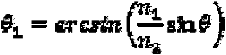
donde n1 y n2 son los índices de refracción del aire y el material del cuerpo lenticular 24.where n1 and n2 are the refractive indices of the air and the material of the lenticular body 24.
Se identifica una coordenada x1 en el cordón de soldadura dependiendo de la altura h del cuerpo lenticular 24.A coordinate x1 is identified in the weld bead depending on the height h of the lenticular body 24.

El área irradiada por la radiación se ubica en una vecindad de x1 que depende de la divergencia del haz de láser y de su forma (figura 14).The area irradiated by radiation is located in a neighborhood of x1 which depends on the divergence of the laser beam and its shape (figure 14).
Para tener una soldadura eficaz no debe haber áreas de irradiación oscuras, sombreadas o desiguales en la interfaz 36 o cordón de soldadura. En general los parámetros que afectan a la homogeneidad, habiendo establecido el ángulo de inclinación de las fibras con respecto a las líneas perpendiculares a la superficie y la altura del cuerpo lenticular 24, son la distancia "d" entre las fibras 44 y la forma del haz de láser, por ejemplo, gaussiano. Experimentalmente se ha encontrado que a lo largo de la interfaz 36 de soldadura, la irradiación debe ser al menos el 25% del pico de irradiación máximo (figura 15).For effective welding there should be no dark, shaded or uneven irradiation areas at the interface 36 or weld bead. In general, the parameters that affect homogeneity, having established the angle of inclination of the fibers with respect to the lines perpendicular to the surface and the height of the lenticular body 24, are the distance "d" between the fibers 44 and the shape of the laser beam, eg Gaussian. Experimentally it has been found that along the weld interface 36, the irradiance must be at least 25% of the maximum irradiation peak (FIG. 15).
La figura 15 muestra el valor de irradiación en el eje y que varía de 0 a 100% correspondiente al valor pico; también se resalta el valor umbral del 25%; se ha visto que dicho valor representa el umbral para obtener una soldadura de calidad.Figure 15 shows the irradiation value on the y-axis that varies from 0 to 100% corresponding to the peak value; the 25% threshold value is also highlighted; It has been seen that this value represents the threshold for obtaining a quality weld.
En el caso en el que el borde exterior 32 tenga un perfil irregular o inconstante, puede verse la presencia de una discontinuidad 54.In the case where the outer edge 32 has an irregular or inconsistent profile, the presence of a discontinuity 54 can be seen.
En particular, se hace referencia a un sistema de soldadura con fibras 44 paralelas entre sí y con discontinuidades 54 en el cuerpo lenticular. La discontinuidad 54 provoca una inclinación igual al ángulo de las líneas rectas perpendiculares a la superficie (figura 16).In particular, reference is made to a welding system with fibers 44 parallel to each other and with discontinuities 54 in the lenticular body. The discontinuity 54 causes an inclination equal to the angle of the straight lines perpendicular to the surface (Figure 16).
En este caso, In this case,

Debido a las discontinuidades, las líneas perpendiculares a las superficies están inclinadas entre sí en el ángulo:Due to the discontinuities, the lines perpendicular to the surfaces are inclined to each other at the angle:

es decir,namely,

De este modo, en el cordón de soldadura se definen los siguientes puntos dependiendo de la altura h:In this way, the following points are defined in the weld bead depending on the height h:
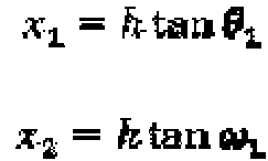
El área irradiada se ubica cerca de x1 y x2 que depende de la divergencia del haz y de su forma (por ejemplo, gaussiano).The irradiated area is located near x1 and x2 which depends on the divergence of the beam and its shape (eg Gaussian).
La discontinuidad 54 del cuerpo lenticular 24 puede definirse como la variación angular de las líneas perpendiculares a la superficie o borde exterior 32 del cuerpo lenticular 24 que genera una distancia entre zonas adyacentes irradiadas x1 y x2 de modo que, entre ellas, la irradiación en la interfaz 36 de soldadura es menos del 25% del valor pico.The discontinuity 54 of the lenticular body 24 can be defined as the angular variation of the lines perpendicular to the surface or outer edge 32 of the lenticular body 24 that generates a distance between adjacent irradiated areas x1 and x2 such that, between them, the irradiation in the solder interface 36 is less than 25% of the peak value.
El método comprende el paso de dirigir al menos un primer haz 60 de láser sobre una porción crítica 64 de la interfaz 36 de soldadura, en el que el primer haz 60 de láser tiene un respectivo eje óptico X-X que se encuentra en un plano óptico P incidente con dicha porción crítica 64 de la interfaz 36 de soldadura.The method comprises the step of directing at least a first laser beam 60 onto a critical portion 64 of the welding interface 36, wherein the first laser beam 60 has a respective optical axis XX that lies in an optical plane P incident with said critical portion 64 of weld interface 36.
De acuerdo con una realización, la porción crítica 64 de la interfaz 36 de soldadura corresponde a dicha discontinuidad 54.According to one embodiment, the critical portion 64 of the weld interface 36 corresponds to said discontinuity 54.
Preferiblemente, el plano óptico P identifica un ángulo de orientación a entre 0 y 45 grados (figura 11a) con un plano T tangente a la porción crítica 64.Preferably, the optical plane P identifies an orientation angle at between 0 and 45 degrees (Figure 11a) with a plane T tangent to the critical portion 64.
De acuerdo con una realización adicional, el plano óptico P identifica un ángulo de orientación a entre 0 y 30 grados con un plano T tangente a la porción crítica 64.According to a further embodiment, the optical plane P identifies an orientation angle at between 0 and 30 degrees with a plane T tangent to the critical portion 64.
De acuerdo con otra realización, el plano óptico P identifica un ángulo de orientación a entre 0 y 10 grados con un plano T tangente a la porción crítica 64.According to another embodiment, the optical plane P identifies an orientation angle at between 0 and 10 degrees with a plane T tangent to the critical portion 64.
De acuerdo con una posible realización, el plano óptico P es sustancialmente paralelo a un plano T tangente a la porción crítica 64.According to one possible embodiment, the optical plane P is substantially parallel to a plane T tangent to the critical portion 64.
Cabe señalar que la porción crítica 64 está sustancialmente asimilada a una porción tangente a la correspondiente abscisa curvilínea s, definida anteriormente.It should be noted that the critical portion 64 is substantially assimilated to a portion tangent to the corresponding curvilinear abscissa s, defined above.
En otras palabras, una porción curva de la interfaz 36 de soldadura se asimila a una porción tangente correspondiente que identifica la dirección del plano tangente T.In other words, a curved portion of the weld interface 36 is assimilated to a corresponding tangent portion that identifies the direction of the tangent plane T.
Se entiende que la porción crítica 64 significa la porción de la interfaz 36 de soldadura correspondiente, es decir, alineada, en una dirección perpendicular a dicha interfaz de soldadura, con la discontinuidad 54.Critical portion 64 is understood to mean the portion of weld interface 36 corresponding, ie aligned, in a direction perpendicular to said weld interface, with discontinuity 54.
Dicha porción de la interfaz 36 de soldadura se define como una porción crítica 64 dado que, debido a la geometría del cuerpo lenticular 24, es decir, debido a la presencia de dicha discontinuidad 54, es difícil de alcanzar con el haz de láser emitido por el fibras 44; en otras palabras, la geometría de las discontinuidades tiende a desviar el haz de láser que falla, en las soluciones de la técnica anterior, para alcanzar óptimamente la porción correspondiente (es decir, subyacente) de la interfaz 36 de soldadura, por dicha razón definida como "crítica". En otras palabras, de nuevo, la geometría de dicha discontinuidad, aplicando los métodos de la técnica anterior, produce una especie de zona de sombra mal irradiada y difícil de irradiar por el haz de láser procedente de las fibras 44.Said portion of the welding interface 36 is defined as a critical portion 64 since, due to the geometry of the lenticular body 24, that is, due to the presence of said discontinuity 54, it is difficult to reach with the laser beam emitted by the fibers 44; In other words, the geometry of the discontinuities tends to deflect the failing laser beam, in prior art solutions, to optimally reach the corresponding (i.e. underlying) portion of the weld interface 36, for said defined reason. as "critical". In other words, from Again, the geometry of said discontinuity, applying the methods of the prior art, produces a kind of poorly irradiated shadow zone that is difficult to irradiate by the laser beam coming from the fibers 44.
Ventajosamente, de acuerdo con la presente invención, la orientación del plano óptico P con el plano T, tangente a la porción crítica 64, en un ángulo de orientación a entre 0 y 45 grados permite una irradiación óptima de la porción crítica 64.Advantageously, according to the present invention, the orientation of the optical plane P with the plane T, tangent to the critical portion 64, at an orientation angle at between 0 and 45 degrees allows optimal irradiation of the critical portion 64.
También es posible, con el fin de aumentar el grado de irradiación de la porción crítica 64, preparar para el paso de dirigir un par de haces 68 de láser sobre la porción crítica 64 de la interfaz 36 de soldadura; de acuerdo con una realización, dicha porción crítica 64 de la interfaz 36 de soldadura corresponde a la discontinuidad 54.It is also possible, in order to increase the degree of irradiation of the critical portion 64, to prepare for the step of directing a pair of laser beams 68 onto the critical portion 64 of the welding interface 36; According to one embodiment, said critical portion 64 of weld interface 36 corresponds to discontinuity 54.
En particular, dichos haces 68 de láser tienen respectivos ejes ópticos X-X que se encuentran en el mismo plano óptico P paralelo a dicha porción crítica 64, en el cual dichos ejes ópticos X-X están dispuestos simétricamente en lados opuestos de un punto medio M de la porción crítica 64 de la interfaz 36 de soldadura.In particular, said laser beams 68 have respective optical axes XX that lie in the same optical plane P parallel to said critical portion 64, in which said optical axes XX are symmetrically arranged on opposite sides of a midpoint M of the portion. Critical 64 of the weld interface 36.
De acuerdo con una realización, el método comprende el paso de dirigir una pluralidad de 'n' haces de láser, cada uno distribuido por una fibra 44 respectiva, sobre la porción crítica 64 de la interfaz 36 de soldadura, teniendo dichos haces de láser respectivos ejes ópticos X que se encuentran en el mismo plano óptico paralelo a dicha porción crítica 64 de la interfaz 36 de soldadura.According to one embodiment, the method comprises the step of directing a plurality of 'n' laser beams, each distributed by a respective fiber 44, onto the critical portion 64 of the welding interface 36, said respective laser beams having optical axes X that lie in the same optical plane parallel to said critical portion 64 of welding interface 36.
El par de haces 68 de láser comprende ejes ópticos X-X inclinados sobre el respectivo plano óptico P para compensar la refracción de los haces 68 de láser que se produce en la incidencia del haz de láser en el borde exterior 32 del cuerpo lenticular 24.The pair of laser beams 68 comprises optical axes X-X inclined on the respective optical plane P to compensate for the refraction of the laser beams 68 that occurs at the incidence of the laser beam at the outer edge 32 of the lenticular body 24.
En presencia de porciones del cuerpo lenticular 24 sin discontinuidades 54 o cambios en la distancia entre el borde exterior 32 del cuerpo lenticular 24 y el segundo perfil perimetral 28, se proporciona un paso para dirigir al menos un haz de láser, sobre una correspondiente porción no crítica 72 de la interfaz 36 de soldadura.In the presence of portions of the lenticular body 24 without discontinuities 54 or changes in the distance between the outer edge 32 of the lenticular body 24 and the second perimeter profile 28, a passage is provided to direct at least one laser beam, onto a corresponding non-portion. Critical 72 of the weld interface 36.
En particular, dicho haz 60 de láser tiene un eje óptico respectivo Y-Y que se encuentra en un segundo plano óptico Z incidente con dicha porción no crítica 72 de la interfaz 36 de soldadura, en el que el segundo plano óptico Z se identifica con un plano R tangente a la porción no crítica 72, un ángulo de orientación p entre 46 y 90 grados.In particular, said laser beam 60 has a respective optical axis YY that lies in a second optical plane Z incident with said non-critical portion 72 of the welding interface 36, wherein the second optical plane Z is identified with a plane R tangent to the non-critical portion 72, an orientation angle p between 46 and 90 degrees.
De acuerdo con una posible realización, el haz de láser tiene un eje óptico respectivo X-X que se encuentra en un segundo plano óptico Z sustancialmente perpendicular a dicha porción no crítica 72 de la interfaz 36 de soldadura. También es posible proporcionar la dirección de un par de haces 68 de láser sobre la porción no crítica 72 de la interfaz 36 de soldadura, teniendo dichos haces 68 de láser respectivos ejes ópticos X-X que se encuentran en el mismo segundo plano óptico Z incidente sobre dicha porción no crítica 72 de la interfaz 36 de soldadura, en la que dichos ejes ópticos X-X están dispuestos simétricamente en lados opuestos de la porción no crítica 72 de la interfaz 36 de soldadura.According to a possible embodiment, the laser beam has a respective optical axis X-X that lies in a second optical plane Z substantially perpendicular to said non-critical portion 72 of the welding interface 36. It is also possible to provide the direction of a pair of laser beams 68 on the non-critical portion 72 of the welding interface 36, said laser beams 68 having respective optical axes XX that lie in the same second optical plane Z incident on said non-critical portion 72 of the welding interface 36, wherein said optical axes XX are symmetrically disposed on opposite sides of the non-critical portion 72 of the welding interface 36.
De acuerdo con una realización, se proporciona un paso para dirigir una pluralidad de 'n' haces de láser, cada uno distribuido por una fibra 44 respectiva, sobre la porción no crítica 72 de la interfaz 36 de soldadura, teniendo dichos haces de láser respectivos ejes ópticos X que se encuentran en el mismo plano óptico paralelo a dicha porción no crítica 72.According to one embodiment, a step is provided for directing a plurality of 'n' laser beams, each distributed by a respective fiber 44, onto the non-critical portion 72 of the welding interface 36, said respective laser beams having optical axes X that are in the same optical plane parallel to said non-critical portion 72.
Como se mencionó anteriormente, el método de soldadura proporciona el uso de dispositivos ópticos 52 para cambiar la divergencia del haz 60, 68 de láser en la salida de las fibras 44.As mentioned above, the welding method provides for the use of optical devices 52 to change the divergence of the laser beam 60, 68 at the exit of the fibers 44.
De acuerdo con una realización, dichos dispositivos ópticos 52 comprenden una guía 76 de luz negativa provista de una entrada 80 y una salida 84, en la que la entrada 80 está orientada hacia dichas fibras 44 y la salida 84 está orientada hacia dicho cuerpo lenticular 24.According to one embodiment, said optical devices 52 comprise a negative light guide 76 provided with an inlet 80 and an outlet 84, in which the inlet 80 is oriented towards said fibers 44 and the outlet 84 is oriented towards said lenticular body 24 .
Por ejemplo, la guía 76 de luz negativa comprende un par de paredes reflectantes 88 inclinadas especularmente con respecto a un plano intermedio 92 en el que se encuentra dicho eje óptico X-X del haz 60, 68 de láser, para converger hacia el cuerpo lenticular 24.For example, the negative light guide 76 comprises a pair of reflective walls 88 inclined specularly with respect to an intermediate plane 92 in which said optical axis X-X of the laser beam 60, 68 is located, to converge towards the lenticular body 24.
En otras palabras, las paredes inclinadas son convergentes para definir una geometría general en forma de cuña que se estrecha moviéndose desde las fibras 44 hacia el cuerpo lenticular 24, así como desde la entrada 80 a la salida 84.In other words, the sloping walls are convergent to define an overall wedge-shaped geometry that tapers moving from fibers 44 toward lenticular body 24, as well as from inlet 80 to outlet 84.
De acuerdo con una realización, la salida 84 de la guía de luz negativa tiene una forma contraria al borde exterior 32 del cuerpo lenticular 24, de modo que forme un acoplamiento conformado con el borde exterior 32 del cuerpo lenticular 24. De esta manera es posible usar la guía de luz negativa como dispositivo de prensador del cuerpo lenticular 24 contra el cuerpo 8 de contenedor, para facilitar la soldadura y/o interpenetración parcial de los perfiles perimetrales primero y segundo 20, 28. According to one embodiment, the outlet 84 of the negative light guide is shaped contrary to the outer edge 32 of the lenticular body 24, so as to form a conformed coupling with the outer edge 32 of the lenticular body 24. In this way it is possible use the negative light guide as a pressing device of the lenticular body 24 against the container body 8, to facilitate the welding and / or partial interpenetration of the first and second perimeter profiles 20, 28.
Como se ve, una guía de luz negativa tiende a distribuir la radiación de láser de dicha salida 84 de acuerdo con una distribución espacial que comprende una pluralidad de porciones o lóbulos Ln, donde al menos un lóbulo L0 se extiende a lo largo de dicho eje óptico X-X. En otras palabras, de acuerdo con la presente invención, la fibra 44 se inclina para tener al menos un lóbulo L0 que se extiende a lo largo de dicho eje óptico X-X, para dirigir dicho lóbulo L0 sobre la interfaz 36 de soldadura.As seen, a negative light guide tends to distribute the laser radiation from said output 84 according to a spatial distribution comprising a plurality of portions or lobes Ln, where at least one lobe L0 extends along said axis. optical XX. In other words, according to the present invention, the fiber 44 is inclined to have at least one lobe L0 extending along said optical axis X-X, to direct said lobe L0 onto the welding interface 36.
De acuerdo con otra realización, el haz de luz distribuido desde la salida 84 de la guía 76 de luz negativa comprende una pluralidad de lóbulos Li, dirigidos hacia el cuerpo lenticular 24, teniendo dichos lóbulos Ln un nivel 'n', donde 'n' es el número de reflejos que experimenta el lóbulo al pasar a través del cuerpo lenticular 24 antes de impactar en la interfaz 36 de soldadura. Lóbulos de diferente grado impactan en la interfaz de soldadura atravesando el cuerpo lenticular y experimentando un número diferente de reflejos dentro del cuerpo lenticular 24.According to another embodiment, the light beam distributed from the exit 84 of the negative light guide 76 comprises a plurality of lobes Li, directed towards the lenticular body 24, said lobes Ln having a level 'n', where 'n' is the number of reflections the lobe experiences as it passes through the lenticular body 24 before impacting the weld interface 36. Lobes of different degrees impact the weld interface passing through the lenticular body and experiencing a different number of reflections within the lenticular body 24.
Preferiblemente, se produce al menos un lóbulo L0 que tiene un grado '0' que impacta en la interfaz 36 de soldadura cruzando el cuerpo lenticular 24 sin experimentar reflejos en el interior de este último.Preferably, at least one lobe L0 is produced having a '0' degree that impacts the weld interface 36 by crossing the lenticular body 24 without experiencing reflections within the latter.
De acuerdo con otra realización, el dispositivo óptico 52 comprende un cuerpo sólido, es decir, una guía de luz positiva, adecuada para satisfacer la condición de reflexión interna total para al menos dicha porción del haz de láser, extendiéndose el cuerpo sólido desde una entrada a una salida, en el que la entrada está orientada hacia dichas fibras 44 y la salida está orientada hacia dicho cuerpo lenticular 24; en tal realización, el cuerpo sólido está compuesto de un material transparente a la longitud de onda de emisión del haz de láser.According to another embodiment, the optical device 52 comprises a solid body, that is, a positive light guide, suitable to satisfy the condition of total internal reflection for at least said portion of the laser beam, the solid body extending from an input to an outlet, wherein the inlet faces said fibers 44 and the outlet faces said lenticular body 24; In such an embodiment, the solid body is composed of a material transparent at the emission wavelength of the laser beam.
Cabe señalar que, tanto en el caso de una guía de luz negativa como en el caso de una guía de luz positiva, la guía de luz controla, o distribuye, la radiación de láser a lo largo del plano transversal a dicha guía de luz, sin controlar la radiación de láser a lo largo del plano longitudinal o tangente a dicha guía de luz.It should be noted that, both in the case of a negative light guide and in the case of a positive light guide, the light guide controls, or distributes, the laser radiation along the plane transverse to said light guide, without controlling the laser radiation along the longitudinal plane or tangent to said light guide.
Como puede apreciarse por la descripción, el método de fabricación de acuerdo con la invención hace posible superar los inconvenientes de la técnica anterior.As can be seen from the description, the manufacturing method according to the invention makes it possible to overcome the drawbacks of the prior art.
En particular, gracias al método de la presente invención es posible aplicar también la técnica de soldadura de láser a luces de automóvil que tengan cualquier tipo de geometría compleja, que tengan curvaturas y grosores muy variables a lo largo del perímetro de la luz.In particular, thanks to the method of the present invention, it is also possible to apply the laser welding technique to automobile lights that have any type of complex geometry, that have highly variable curvatures and thicknesses along the perimeter of the light.
La técnica de soldadura de láser de acuerdo con la presente invención no solo no es inconveniente en comparación con las técnicas de soldadura alternativas de la técnica anterior, sino que incluso puede ser mejor tanto en términos de coste como de tiempo, para la misma calidad de la junta de soldadura, en comparación con las soluciones de la técnica anterior en el campo de las luces de automóvil.The laser welding technique according to the present invention is not only not inconvenient compared to the alternative welding techniques of the prior art, but it can even be better both in terms of cost and time, for the same quality of the solder joint, compared to the prior art solutions in the field of automobile lights.
En particular, hay una reducción del consumo y, por lo tanto, de los costes ya que una mayor parte del haz de luz puede transmitirse a la interfaz de soldadura entre el cuerpo lenticular y el cuerpo de contenedor.In particular, there is a reduction in consumption and therefore in costs since a greater part of the light beam can be transmitted to the welding interface between the lenticular body and the container body.
El haz de luz en la porción de interfaz de soldadura entre el cuerpo lenticular y el cuerpo de contenedor es por tanto adecuado para obtener una junta soldada que tiene excelentes cualidades mecánicas, sin pérdida de potencia luminosa.The light beam at the welding interface portion between the lenticular body and the container body is therefore suitable to obtain a welded joint having excellent mechanical qualities, without loss of light power.
Además, al proporcionar una porción de guía de luz que coopera con la guía de luz del distribuidor de la radiación de láser, es posible controlar de manera más eficiente la radiación de láser destinada al área de soldadura con respecto a la enseñanza de la técnica anterior, especialmente en la soldadura de láser de cuerpos lenticulares que tienen discontinuidades superficiales. En el presente caso, al menos un lóbulo de la distribución de radiación de láser en la salida de la boca del distribuidor de radiación de láser puede evitar una posible discontinuidad superficial del cuerpo lenticular, ya que puede llegar a su destino transportado en la porción de guía de luz del cuerpo lenticular.In addition, by providing a light guide portion that cooperates with the light guide of the laser radiation distributor, it is possible to more efficiently control the laser radiation intended for the welding area with respect to the teaching of the prior art. , especially in laser welding of lenticular bodies that have surface discontinuities. In the present case, at least one lobe of the laser radiation distribution at the outlet of the mouth of the laser radiation distributor can avoid a possible surface discontinuity of the lenticular body, since it can reach its destination transported in the portion of lenticular body light guide.
Una persona experta en la técnica puede realizar numerosas modificaciones y variaciones a los métodos de fabricación de luces de automóvil descritos anteriormente para satisfacer requisitos contingentes y específicos mientras permanece dentro del ámbito de protección de la invención como se define en las siguientes reivindicaciones. A person skilled in the art can make numerous modifications and variations to the automotive light manufacturing methods described above to satisfy contingent and specific requirements while remaining within the scope of protection of the invention as defined in the following claims.
Claims (19)
Applications Claiming Priority (1)
| Application Number | Priority Date | Filing Date | Title |
|---|---|---|---|
| ITPD20140135 | 2014-05-30 |
Publications (1)
| Publication Number | Publication Date |
|---|---|
| ES2818627T3 true ES2818627T3 (en) | 2021-04-13 |
Family
ID=51454833
Family Applications (1)
| Application Number | Title | Priority Date | Filing Date |
|---|---|---|---|
| ES15165724T Active ES2818627T3 (en) | 2014-05-30 | 2015-04-29 | Laser welding method of a car light |
Country Status (9)
| Country | Link |
|---|---|
| US (1) | US9757896B2 (en) |
| EP (1) | EP2949452B1 (en) |
| JP (1) | JP6612058B2 (en) |
| KR (1) | KR102379090B1 (en) |
| CN (1) | CN105269151B (en) |
| ES (1) | ES2818627T3 (en) |
| HR (1) | HRP20201551T1 (en) |
| HU (1) | HUE052369T2 (en) |
| PL (1) | PL2949452T3 (en) |
Families Citing this family (13)
| Publication number | Priority date | Publication date | Assignee | Title |
|---|---|---|---|---|
| EP2957418B1 (en) * | 2014-06-19 | 2020-01-01 | Marelli Automotive Lighting Italy S.p.A. | Apparatus for making an automotive headlight and method of simultaneous laser welding of an automotive headlight |
| DE102016116137A1 (en) * | 2016-08-30 | 2018-03-01 | HELLA GmbH & Co. KGaA | Method and device for joining a lens with a housing of a lighting device for a motor vehicle |
| IT201700041997A1 (en) * | 2017-04-14 | 2018-10-14 | Automotive Lighting Italia Spa | Simultaneous laser welding equipment of an automotive headlight and simultaneous laser welding method of an automotive headlight |
| EP3395547B1 (en) | 2017-04-28 | 2020-02-12 | Leister Technologies AG | Laser joining method and laser joining system for welding workpieces |
| CN108692282B (en) * | 2017-08-24 | 2024-06-25 | 常州星宇车灯股份有限公司 | Rear combined lamp for vehicle |
| IT201700114962A1 (en) * | 2017-10-12 | 2019-04-12 | Automotive Lighting Italia Spa | SIMULTANEOUS LASER WELDING EQUIPMENT FOR A AUTOMOTIVE HEADLAMP AND SIMULTANEOUS LASER WELDING METHOD OF A AUTOMOTIVE HEADLAMP |
| DE102018104629A1 (en) * | 2018-02-28 | 2019-08-29 | Branson Ultraschall Niederlassung Der Emerson Technologies Gmbh & Co. Ohg | Waveguide for plastic welding, assembly for plastic welding, a welding method and a method of manufacturing a waveguide |
| US11566769B2 (en) * | 2018-04-25 | 2023-01-31 | Koito Manufacturing Co., Ltd. | Vehicle lamp |
| EP3659788B1 (en) | 2018-11-27 | 2022-05-18 | Branson Ultraschall Niederlassung der Emerson Technologies GmbH & Co. oHG | Waveguide segment for plastic welding, arrangement for plastic welding, a welding method as well as a manufacturing method of a waveguide segment |
| KR102261162B1 (en) * | 2021-01-28 | 2021-06-08 | (주)이브이레이저 | Laser plastic welding apparatus |
| KR102261161B1 (en) * | 2021-01-28 | 2021-06-08 | (주)이브이레이저 | Laser plastic welding apparatus |
| EP4234213A1 (en) * | 2022-02-28 | 2023-08-30 | Ostbayerische Technische Hochschule Regensburg | Laser welding device for clamping and welding components and method for clamping and welding components |
| EP4527595A1 (en) * | 2023-09-25 | 2025-03-26 | Marelli Automotive Lighting Italy S.p.A. Con Socio Unico | Assembly method of an automotive lighting unit and machine implementing such method |
Family Cites Families (17)
| Publication number | Priority date | Publication date | Assignee | Title |
|---|---|---|---|---|
| JPH11348132A (en) | 1998-06-02 | 1999-12-21 | Stanley Electric Co Ltd | Laser welding method and laser welding device |
| JP3973792B2 (en) | 1999-04-12 | 2007-09-12 | 株式会社小糸製作所 | Manufacturing method of vehicular lamp |
| JP3961737B2 (en) | 2000-02-29 | 2007-08-22 | 株式会社小糸製作所 | Vehicular lamp and manufacturing method thereof |
| CN1443103A (en) | 2000-04-11 | 2003-09-17 | 布兰森超音波学公司 | Light guide for laser welding |
| JP4731040B2 (en) | 2001-05-11 | 2011-07-20 | 本田技研工業株式会社 | Laser welding method |
| JP4318503B2 (en) | 2003-08-05 | 2009-08-26 | 株式会社小糸製作所 | Vehicular lamp and manufacturing method thereof |
| EP1518664A1 (en) * | 2003-09-20 | 2005-03-30 | Leister Process Technologies | Process and apparatus for joining components by laser radiation |
| US20050121424A1 (en) | 2003-12-05 | 2005-06-09 | Scott Caldwell | Optical horned lightpipe or lightguide |
| JP2006073296A (en) | 2004-09-01 | 2006-03-16 | Koito Mfg Co Ltd | Vehicle lamp and laser welding method for vehicle lamp |
| JP4717468B2 (en) | 2005-02-23 | 2011-07-06 | 浜松ホトニクス株式会社 | Laser processing equipment |
| FR2952316B1 (en) * | 2009-11-06 | 2012-03-02 | Valeo Vision | LASER WELDING PROCESS |
| JP5911199B2 (en) * | 2011-03-22 | 2016-04-27 | 株式会社小糸製作所 | Welding method and welding apparatus |
| JP2013196891A (en) * | 2012-03-19 | 2013-09-30 | Stanley Electric Co Ltd | Manufacturing method of vehicular lamp |
| JP6005457B2 (en) * | 2012-09-21 | 2016-10-12 | 株式会社小糸製作所 | Welding method and welding apparatus |
| DE102012220507A1 (en) * | 2012-11-09 | 2014-05-15 | Automotive Lighting Reutlingen Gmbh | Light module for a headlight of a motor vehicle |
| EP2923820B1 (en) | 2014-03-28 | 2018-12-19 | Automotive Lighting Italia S.p.A. A Socio Unico | Method of laser welding of an automotive light |
| EP2923819B1 (en) | 2014-03-28 | 2019-09-04 | Automotive Lighting Italia S.p.A. A Socio Unico | Method of manufacture of an automotive light |
-
2015
- 2015-04-29 HU HUE15165724A patent/HUE052369T2/en unknown
- 2015-04-29 ES ES15165724T patent/ES2818627T3/en active Active
- 2015-04-29 EP EP15165724.4A patent/EP2949452B1/en not_active Revoked
- 2015-04-29 PL PL15165724T patent/PL2949452T3/en unknown
- 2015-05-28 KR KR1020150075291A patent/KR102379090B1/en not_active Expired - Fee Related
- 2015-05-28 US US14/723,782 patent/US9757896B2/en active Active
- 2015-05-29 CN CN201510288950.3A patent/CN105269151B/en active Active
- 2015-05-29 JP JP2015110181A patent/JP6612058B2/en active Active
-
2020
- 2020-09-29 HR HRP20201551TT patent/HRP20201551T1/en unknown
Also Published As
| Publication number | Publication date |
|---|---|
| PL2949452T3 (en) | 2020-11-30 |
| KR102379090B1 (en) | 2022-03-24 |
| JP6612058B2 (en) | 2019-11-27 |
| US20150343701A1 (en) | 2015-12-03 |
| US9757896B2 (en) | 2017-09-12 |
| CN105269151B (en) | 2018-09-11 |
| JP2016021383A (en) | 2016-02-04 |
| EP2949452B1 (en) | 2020-07-01 |
| KR20150138080A (en) | 2015-12-09 |
| HRP20201551T1 (en) | 2021-02-19 |
| HUE052369T2 (en) | 2021-04-28 |
| CN105269151A (en) | 2016-01-27 |
| EP2949452A1 (en) | 2015-12-02 |
Similar Documents
| Publication | Publication Date | Title |
|---|---|---|
| ES2818627T3 (en) | Laser welding method of a car light | |
| ES2781854T3 (en) | Apparatus for making a car headlight and simultaneous laser welding method of a car headlight | |
| ES2715876T3 (en) | Laser welding method of a car light | |
| ES2962345T3 (en) | Simultaneous laser welding apparatus and method for simultaneous laser welding of a vehicle light | |
| JP6108185B2 (en) | Light guide member for vehicle laser headlamp | |
| US9458986B2 (en) | Lighting unit | |
| ES2532713T3 (en) | Device for joining two parts of a workpiece by means of a welding bead by transmission welding | |
| ES2857603T3 (en) | Method of manufacturing a vehicle light and related vehicle light | |
| JP5688952B2 (en) | Vehicle lighting | |
| US20190170315A1 (en) | Lighting device and vehicular headlamp | |
| MX2014010935A (en) | Optical element for a laser vehicle headlight. | |
| JP7472618B2 (en) | Light guide for vehicle and vehicle lamp unit | |
| US20220184739A1 (en) | Simultaneous Laser Welding Equipment of a Vehicle Light and Simultaneous Laser Welding Method of a Vehicle Light | |
| US10137627B2 (en) | Unit for processing blanks provided with an optical confinement section having convergent walls | |
| JP4574573B2 (en) | Vehicle lamp unit | |
| KR102125821B1 (en) | Illuminating device for vehicle | |
| CN104608374B (en) | Cladding method and deposition apparatus | |
| JP2013033622A (en) | Lamp fitting |