EP4583381A2 - Intravaskuläre blutpumpe mit mehrschichtigen kernlosen spulen - Google Patents
Intravaskuläre blutpumpe mit mehrschichtigen kernlosen spulen Download PDFInfo
- Publication number
- EP4583381A2 EP4583381A2 EP25177814.8A EP25177814A EP4583381A2 EP 4583381 A2 EP4583381 A2 EP 4583381A2 EP 25177814 A EP25177814 A EP 25177814A EP 4583381 A2 EP4583381 A2 EP 4583381A2
- Authority
- EP
- European Patent Office
- Prior art keywords
- coils
- stator
- winding
- coil
- phase
- Prior art date
- Legal status (The legal status is an assumption and is not a legal conclusion. Google has not performed a legal analysis and makes no representation as to the accuracy of the status listed.)
- Pending
Links
Images




Classifications
-
- A—HUMAN NECESSITIES
- A61—MEDICAL OR VETERINARY SCIENCE; HYGIENE
- A61M—DEVICES FOR INTRODUCING MEDIA INTO, OR ONTO, THE BODY; DEVICES FOR TRANSDUCING BODY MEDIA OR FOR TAKING MEDIA FROM THE BODY; DEVICES FOR PRODUCING OR ENDING SLEEP OR STUPOR
- A61M60/00—Blood pumps; Devices for mechanical circulatory actuation; Balloon pumps for circulatory assistance
- A61M60/10—Location thereof with respect to the patient's body
- A61M60/122—Implantable pumps or pumping devices, i.e. the blood being pumped inside the patient's body
- A61M60/126—Implantable pumps or pumping devices, i.e. the blood being pumped inside the patient's body implantable via, into, inside, in line, branching on, or around a blood vessel
- A61M60/13—Implantable pumps or pumping devices, i.e. the blood being pumped inside the patient's body implantable via, into, inside, in line, branching on, or around a blood vessel by means of a catheter allowing explantation, e.g. catheter pumps temporarily introduced via the vascular system
-
- A—HUMAN NECESSITIES
- A61—MEDICAL OR VETERINARY SCIENCE; HYGIENE
- A61M—DEVICES FOR INTRODUCING MEDIA INTO, OR ONTO, THE BODY; DEVICES FOR TRANSDUCING BODY MEDIA OR FOR TAKING MEDIA FROM THE BODY; DEVICES FOR PRODUCING OR ENDING SLEEP OR STUPOR
- A61M60/00—Blood pumps; Devices for mechanical circulatory actuation; Balloon pumps for circulatory assistance
- A61M60/10—Location thereof with respect to the patient's body
- A61M60/122—Implantable pumps or pumping devices, i.e. the blood being pumped inside the patient's body
- A61M60/126—Implantable pumps or pumping devices, i.e. the blood being pumped inside the patient's body implantable via, into, inside, in line, branching on, or around a blood vessel
- A61M60/135—Implantable pumps or pumping devices, i.e. the blood being pumped inside the patient's body implantable via, into, inside, in line, branching on, or around a blood vessel inside a blood vessel, e.g. using grafting
-
- A—HUMAN NECESSITIES
- A61—MEDICAL OR VETERINARY SCIENCE; HYGIENE
- A61M—DEVICES FOR INTRODUCING MEDIA INTO, OR ONTO, THE BODY; DEVICES FOR TRANSDUCING BODY MEDIA OR FOR TAKING MEDIA FROM THE BODY; DEVICES FOR PRODUCING OR ENDING SLEEP OR STUPOR
- A61M60/00—Blood pumps; Devices for mechanical circulatory actuation; Balloon pumps for circulatory assistance
- A61M60/10—Location thereof with respect to the patient's body
- A61M60/122—Implantable pumps or pumping devices, i.e. the blood being pumped inside the patient's body
- A61M60/165—Implantable pumps or pumping devices, i.e. the blood being pumped inside the patient's body implantable in, on, or around the heart
- A61M60/17—Implantable pumps or pumping devices, i.e. the blood being pumped inside the patient's body implantable in, on, or around the heart inside a ventricle, e.g. intraventricular balloon pumps
-
- A—HUMAN NECESSITIES
- A61—MEDICAL OR VETERINARY SCIENCE; HYGIENE
- A61M—DEVICES FOR INTRODUCING MEDIA INTO, OR ONTO, THE BODY; DEVICES FOR TRANSDUCING BODY MEDIA OR FOR TAKING MEDIA FROM THE BODY; DEVICES FOR PRODUCING OR ENDING SLEEP OR STUPOR
- A61M60/00—Blood pumps; Devices for mechanical circulatory actuation; Balloon pumps for circulatory assistance
- A61M60/20—Type thereof
- A61M60/205—Non-positive displacement blood pumps
- A61M60/216—Non-positive displacement blood pumps including a rotating member acting on the blood, e.g. impeller
- A61M60/237—Non-positive displacement blood pumps including a rotating member acting on the blood, e.g. impeller the blood flow through the rotating member having mainly axial components, e.g. axial flow pumps
-
- A—HUMAN NECESSITIES
- A61—MEDICAL OR VETERINARY SCIENCE; HYGIENE
- A61M—DEVICES FOR INTRODUCING MEDIA INTO, OR ONTO, THE BODY; DEVICES FOR TRANSDUCING BODY MEDIA OR FOR TAKING MEDIA FROM THE BODY; DEVICES FOR PRODUCING OR ENDING SLEEP OR STUPOR
- A61M60/00—Blood pumps; Devices for mechanical circulatory actuation; Balloon pumps for circulatory assistance
- A61M60/40—Details relating to driving
- A61M60/403—Details relating to driving for non-positive displacement blood pumps
- A61M60/408—Details relating to driving for non-positive displacement blood pumps the force acting on the blood contacting member being mechanical, e.g. transmitted by a shaft or cable
- A61M60/411—Details relating to driving for non-positive displacement blood pumps the force acting on the blood contacting member being mechanical, e.g. transmitted by a shaft or cable generated by an electromotor
- A61M60/416—Details relating to driving for non-positive displacement blood pumps the force acting on the blood contacting member being mechanical, e.g. transmitted by a shaft or cable generated by an electromotor transmitted directly by the motor rotor drive shaft
-
- A—HUMAN NECESSITIES
- A61—MEDICAL OR VETERINARY SCIENCE; HYGIENE
- A61M—DEVICES FOR INTRODUCING MEDIA INTO, OR ONTO, THE BODY; DEVICES FOR TRANSDUCING BODY MEDIA OR FOR TAKING MEDIA FROM THE BODY; DEVICES FOR PRODUCING OR ENDING SLEEP OR STUPOR
- A61M60/00—Blood pumps; Devices for mechanical circulatory actuation; Balloon pumps for circulatory assistance
- A61M60/40—Details relating to driving
- A61M60/403—Details relating to driving for non-positive displacement blood pumps
- A61M60/419—Details relating to driving for non-positive displacement blood pumps the force acting on the blood contacting member being permanent magnetic, e.g. from a rotating magnetic coupling between driving and driven magnets
-
- A—HUMAN NECESSITIES
- A61—MEDICAL OR VETERINARY SCIENCE; HYGIENE
- A61M—DEVICES FOR INTRODUCING MEDIA INTO, OR ONTO, THE BODY; DEVICES FOR TRANSDUCING BODY MEDIA OR FOR TAKING MEDIA FROM THE BODY; DEVICES FOR PRODUCING OR ENDING SLEEP OR STUPOR
- A61M60/00—Blood pumps; Devices for mechanical circulatory actuation; Balloon pumps for circulatory assistance
- A61M60/40—Details relating to driving
- A61M60/403—Details relating to driving for non-positive displacement blood pumps
- A61M60/422—Details relating to driving for non-positive displacement blood pumps the force acting on the blood contacting member being electromagnetic, e.g. using canned motor pumps
-
- A—HUMAN NECESSITIES
- A61—MEDICAL OR VETERINARY SCIENCE; HYGIENE
- A61M—DEVICES FOR INTRODUCING MEDIA INTO, OR ONTO, THE BODY; DEVICES FOR TRANSDUCING BODY MEDIA OR FOR TAKING MEDIA FROM THE BODY; DEVICES FOR PRODUCING OR ENDING SLEEP OR STUPOR
- A61M60/00—Blood pumps; Devices for mechanical circulatory actuation; Balloon pumps for circulatory assistance
- A61M60/50—Details relating to control
-
- A—HUMAN NECESSITIES
- A61—MEDICAL OR VETERINARY SCIENCE; HYGIENE
- A61M—DEVICES FOR INTRODUCING MEDIA INTO, OR ONTO, THE BODY; DEVICES FOR TRANSDUCING BODY MEDIA OR FOR TAKING MEDIA FROM THE BODY; DEVICES FOR PRODUCING OR ENDING SLEEP OR STUPOR
- A61M60/00—Blood pumps; Devices for mechanical circulatory actuation; Balloon pumps for circulatory assistance
- A61M60/50—Details relating to control
- A61M60/508—Electronic control means, e.g. for feedback regulation
-
- H—ELECTRICITY
- H02—GENERATION; CONVERSION OR DISTRIBUTION OF ELECTRIC POWER
- H02K—DYNAMO-ELECTRIC MACHINES
- H02K1/00—Details of the magnetic circuit
- H02K1/06—Details of the magnetic circuit characterised by the shape, form or construction
- H02K1/22—Rotating parts of the magnetic circuit
- H02K1/27—Rotor cores with permanent magnets
- H02K1/2706—Inner rotors
- H02K1/272—Inner rotors the magnetisation axis of the magnets being perpendicular to the rotor axis
- H02K1/274—Inner rotors the magnetisation axis of the magnets being perpendicular to the rotor axis the rotor consisting of two or more circumferentially positioned magnets
- H02K1/2753—Inner rotors the magnetisation axis of the magnets being perpendicular to the rotor axis the rotor consisting of two or more circumferentially positioned magnets the rotor consisting of magnets or groups of magnets arranged with alternating polarity
- H02K1/278—Surface mounted magnets; Inset magnets
-
- H—ELECTRICITY
- H02—GENERATION; CONVERSION OR DISTRIBUTION OF ELECTRIC POWER
- H02K—DYNAMO-ELECTRIC MACHINES
- H02K15/00—Processes or apparatus specially adapted for manufacturing, assembling, maintaining or repairing of dynamo-electric machines
- H02K15/04—Processes or apparatus specially adapted for manufacturing, assembling, maintaining or repairing of dynamo-electric machines of windings prior to their mounting into the machines
- H02K15/043—Processes or apparatus specially adapted for manufacturing, assembling, maintaining or repairing of dynamo-electric machines of windings prior to their mounting into the machines winding flat conductive wires or sheets
-
- H—ELECTRICITY
- H02—GENERATION; CONVERSION OR DISTRIBUTION OF ELECTRIC POWER
- H02K—DYNAMO-ELECTRIC MACHINES
- H02K21/00—Synchronous motors having permanent magnets; Synchronous generators having permanent magnets
- H02K21/12—Synchronous motors having permanent magnets; Synchronous generators having permanent magnets with stationary armatures and rotating magnets
- H02K21/14—Synchronous motors having permanent magnets; Synchronous generators having permanent magnets with stationary armatures and rotating magnets with magnets rotating within the armatures
-
- H—ELECTRICITY
- H02—GENERATION; CONVERSION OR DISTRIBUTION OF ELECTRIC POWER
- H02K—DYNAMO-ELECTRIC MACHINES
- H02K3/00—Details of windings
- H02K3/04—Windings characterised by the conductor shape, form or construction, e.g. with bar conductors
- H02K3/28—Layout of windings or of connections between windings
-
- H—ELECTRICITY
- H02—GENERATION; CONVERSION OR DISTRIBUTION OF ELECTRIC POWER
- H02K—DYNAMO-ELECTRIC MACHINES
- H02K3/00—Details of windings
- H02K3/46—Fastening of windings on the stator or rotor structure
- H02K3/47—Air-gap windings, i.e. iron-free windings
-
- H—ELECTRICITY
- H02—GENERATION; CONVERSION OR DISTRIBUTION OF ELECTRIC POWER
- H02K—DYNAMO-ELECTRIC MACHINES
- H02K7/00—Arrangements for handling mechanical energy structurally associated with dynamo-electric machines, e.g. structural association with mechanical driving motors or auxiliary dynamo-electric machines
- H02K7/14—Structural association with mechanical loads, e.g. with hand-held machine tools or fans
-
- A—HUMAN NECESSITIES
- A61—MEDICAL OR VETERINARY SCIENCE; HYGIENE
- A61M—DEVICES FOR INTRODUCING MEDIA INTO, OR ONTO, THE BODY; DEVICES FOR TRANSDUCING BODY MEDIA OR FOR TAKING MEDIA FROM THE BODY; DEVICES FOR PRODUCING OR ENDING SLEEP OR STUPOR
- A61M2205/00—General characteristics of the apparatus
- A61M2205/33—Controlling, regulating or measuring
- A61M2205/3331—Pressure; Flow
- A61M2205/3334—Measuring or controlling the flow rate
-
- H—ELECTRICITY
- H02—GENERATION; CONVERSION OR DISTRIBUTION OF ELECTRIC POWER
- H02K—DYNAMO-ELECTRIC MACHINES
- H02K15/00—Processes or apparatus specially adapted for manufacturing, assembling, maintaining or repairing of dynamo-electric machines
- H02K15/02—Processes or apparatus specially adapted for manufacturing, assembling, maintaining or repairing of dynamo-electric machines of stator or rotor bodies
- H02K15/03—Processes or apparatus specially adapted for manufacturing, assembling, maintaining or repairing of dynamo-electric machines of stator or rotor bodies having permanent magnets
Definitions
- the present technology relates to intravascular blood pumps systems with a permanent magnet motor and a stator having coils.
- Intravascular blood pumps such as the Impella ® pump by Abiomed, Inc. of Danvers, MA, are quickly becoming the current standard for ventricular assist devices.
- the range of Impella ® pumps currently comprise the Impella 2.5 ® pump, the Impella 5.0 ® pump, the Impella CP ® pump and the Impella LD ® pump. These pumps are inserted into a patient percutaneously through a single access point (e.g. radial access, femoral access, axillary access) such that the pump head can be placed into the left ventricle of the patient's heart via small diameter (6-7Fr) catheters.
- the pump head comprises an electric motor that includes a stator configured to magnetically interact with a rotor for rotation thereof thereby resulting in a volumetric flow of blood through the rotor and hence through the heart of the patient.
- the blood pump comprises an elongate housing having a proximal end connected to a catheter and a distal end coupled to the pump, the housing having a longitudinal axis.
- the blood pump also comprises a slotless permanent magnet motor contained within the housing, the motor having p magnet pole pairs and n phases, where p is an integer greater than zero, and n is an integer ⁇ 3.
- the motor comprises a stator extending along the longitudinal axis of the housing and having 2np coils wound to form two coils per phase per permanent magnet pole pair.
- the stator comprises an inner winding comprising np coils in which one coil from each phase is arranged next to a coil from a different phase in a sequential order of phase per pole pair, the arrangement repeated about the circumference of the stator for all pole pairs such that each coil of the inner winding spans 360/(np) mechanical degrees about the cross section of the stator, the inner winding having an exterior surface.
- the stator also comprises an outer winding also comprising np coils arranged on the exterior surface of the inner winding, the coils from each phase in the outer winding circumferentially aligned with the coils from the inner winding having the same phase per pole pair such that each coil of the outer winding also spans 360/(np) mechanical degrees about the cross section of the stator.
- the coils of the same phase per pole pair are connected such that the current flowing through the coils is in the same direction.
- the coil windings described herein are formed from magnet wire. Magnet wires are well known to one skilled in the art and are not described in detail herein.
- the motor comprises a magnet supported for rotation upon magnetic interaction with the stator thereby facilitating the flow of blood through the pump.
- a slotless permanent magnet electric motor having p magnet pole pairs and n phases, where p is an integer greater than zero, and n is an integer ⁇ 3, the motor having a longitudinal axis.
- the motor comprises a stator extending along the longitudinal axis of the housing and having 2np coils wound to form two coils per phase per permanent magnet pole pair.
- the stator comprises an inner winding comprising np coils in which one coil from each phase is arranged next to a coil from a different phase in a sequential order of phase per pole pair, the arrangement repeated about the circumference of the stator for all pole pairs such that each coil of the inner winding spans 360/( np ) mechanical degrees about the cross section of the stator, the inner winding having an exterior surface.
- the stator also comprises an outer winding also comprising np coils arranged on the exterior surface of the inner winding, the coils from each phase in the outer winding circumferentially aligned with the coils from the inner winding having the same phase per pole pair such that each coil of the outer winding also spans 360/( np ) mechanical degrees about the cross section of the stator.
- the coils of the same phase per pole pair are connected such that the current flowing through the coils is in the same direction.
- the motor comprises a magnet supported for rotation upon magnetic interaction with the stator thereby facilitating rotation of the rotor.
- the outer winding comprises at least the same number of winding turns as the inner winding.
- each coil comprises two layers of magnet wires, each extending longitudinally along the length of the stator.
- the magnet wires in each coil are arranged next to each other in a sequential order along the span of the coil.
- the inner winding of coils establishes a uniform foundation upon which the outer winding of coils is overlaid.
- the coils of a phase are connected to the coils of the other phases in either a star or a delta configuration. In some implementations, the coils of each phase are connected either in series or in parallel.
- the 2np coils comprise any one of helical windings, rhombic windings, conventional windings and hybrid windings.
- the motor comprises a three-phase one pole pair machine.
- the motor comprises a six-coil two-pole machine, each coil spanning 120 mechanical degrees about the cross section of the stator.
- the rotor pumps blood at a rate between about 1.0 lpm and about 6.0 lpm.
- the pump may be inserted into the right ventricle of the patient's heart.
- the pump may be inserted into the left ventricle of the patient's heart.
- the arrangement of 2np coils wound to form two coils per phase per magnet pole pair in a double winding comprising np coils in an inner winding and np coils in an outer winding enables more wires to be used within the space available within an electric motor, thereby providing for better utilization of the motor space design. This improves the efficiency of the motor compared to motors using single-winding stators.
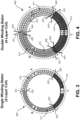
- coils A1-A4 have the same direction of current flowing therethrough, where coils A1 and A3 interact with pole S1, for example, and coils A2 and A4 interact with corresponding pole S2 of the same polarity as pole S1, for example, to cause rotation of the rotor.
- coils B1-B4 have the same direction of current flowing therethrough, where coils B1 and B3 interact with pole N1, for example, and coils A2 and A4 interact with corresponding pole N2 of the same polarity as pole N1, for example, to cause rotation of the rotor.
- coils 810-819 may be electrically connected in either star or delta configuration in which (i) coils 810-811 for phase A are connected in series or in parallel with the start terminal of one coil connected to the end terminal of the next coil along the branch for phase A of the star or delta connection, (ii) coils 812-813 for phase are connected in series or in parallel with the start terminal of one coil connected to the end terminal of the next coil along the branch for phase B of the star or delta connection, (iii) coils 814-815 for phase C are connected in series or in parallel with the start terminal of one coil connected to the end terminal of the next coil along the branch for phase C of the star or delta connection, (iv) coils 816-817 for phase D are connected in series or in parallel with the start terminal of one coil connected to the end terminal of the next coil along the branch for phase D of the star or delta connection, and (v) coils 818-819 for phase E are connected in series or in parallel with the start terminal of one coil connected to
- the double helical winding stator results in an electric motor with an increased coil resistance of 5.40 ⁇ /phase compared to that of the single helical winding stator, and with an increased torque constant of 1.236 ⁇ 10 -3 N ⁇ m/A, i.e. an increase of 40.5% from that of the single helical stator.
- the results in Table 1 confirm that the double-winding stator according to embodiments of the present disclosure reduces the coil joule heat by 40% while motors employing such a double-winding stator produce the same torque to drive the pumps compared to motors using a single-winding stator.
- phase A comprises a coil 'A
- phase B comprises a coil 'B
- phase C comprises a coil 'C'.
- the amount of conductor in each coil of the stator is increased by simply increasing the number of turns of magnet wire in each coil in a random manner.
- the wires are wound without any precision or regularity.
- each of coils A, B and C is formed by the random placement of turns of magnet wires according to the numbers as shown starting at turn 1 and ending at turn 65. Within each coil the turns are placed randomly without any order as the objective is to pack the specific number of magnet wires within each coil.
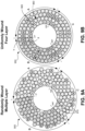
- FIG. 10A illustrates an exemplary randomly wound multiple-layer stator 900 formed using the winding sequence as described in relation to FIG. 9A .
- the random arrangement of wires forming the stator 900 can be seen in FIG. 10A where the magnet wires are irregular and excessively overlapped. This contributes to the irregular winding pattern of the exterior surface of the stator, as seen from the nature of the outer surface of the stator shown in FIG. 10A .
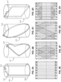
- 9B is formed by winding magnet wires in an ordered sequence along the 120° span of the respective coil about the cross section of the stator between the proximal end of the stator, the magnet wires extending longitudinally towards the distal end, and returning back to the proximal end using any of the coil winding patterns shown in FIGS. 2E-2H .
- a magnet wire When a magnet wire is wound to form a first turn (e.g. turn labelled '1') in each of the coils of the inner winding from the proximal end to the distal end of the stator, a forward portion of the magnet wire of turn 1 is formed in a first layer, and when the magnet wire is wound returning from the distal end to the proximal end, a return portion of the magnet wire (labelled 'X') of the turn 1 is formed in a second layer radially outwardly adjacent the first layer.
- adjacent means “immediately radially next to" (i.e., without anything in between).
- the first turn is formed by a continuous copper wire wound from the proximal end of the stator to the distal end of the stator (forward wire portion arranged in the first layer), and from the distal end of the stator to the proximal end of the stator (return wire portion labelled 'X' arranged in the second layer).
- forward wire portion of turn 1 has a corresponding return wire portion X arranged immediately radially outward from forward wire portion.
- turn labelled '32' is formed from the proximal end to the distal end of the stator where a forward portion of a magnet wire of the first turn 32 is formed in a third layer, and when the magnet wire is wound returning from the distal end to the proximal end, the return portion of the magnet wire (labelled 'Y') of the first turn 32 is formed in a fourth layer radially outwardly adjacent to the third layer.
- the first turn 32 of the outer winding is formed by a continuous magnet wire wound from the proximal end of the stator to the distal end of the stator (forward wire portion arranged in the third layer), and from the distal end of the stator to the proximal end of the stator (return wire portion labelled 'Y' arranged in the fourth layer).
- stator 950 in FIG. 9B where the turns in outer winding 965 are precisely laid in the sequential order of turn 32 to turn 65 in an anticlockwise direction along the 120° span of the respective coils for each of the coils A2, B2 and C2.
- turn 32 of the outer winding is radially aligned with turn 1 of the inner winding
- turn 65 of the wire winding is radially aligned with turn 31 of the inner winding.
- the stator of the present disclosure has an outer winding with a larger number of turns than the inner winding. For example, in FIG.
- An exemplary winding sequence for the formation of stator 950 may have the following order: (1) form turns 1-31 for coil A1, (2) form turns 1-31 for coil B1, (3) form turns 1-31 for coil C1, (4) form turns 32-65 for coil A2 on the exterior surface of coil A1, (5) form turns 32-65 for coil B2 on the exterior surface of coil B1, and (6) form turns 32-65 for coil C2 on the exterior surface of coil C1.
- each turn comprises a forward wire portion and a return wire portion automatically arranged radially adjacent the forward wire portion.
- each coil in the inner winding and outer winding of the stator 950 has a pair of lead wires (such as lead wires 420-421 for coil A1 in FIG. 4 ) for connection to feed lines 146-147 of the electric motor 100.
- thicker wires may be used for the coils forming the inner and outer windings to achieve a comparable resistance as the single-winding stator.
- FIG. 10B illustrates an exemplary stator formed using the winding sequence as described in relation to FIG. 9B according to embodiments of the present disclosure.
- the stator in FIG. 10B comprises wires that are precisely arranged resulting in a uniform outer diameter along the length of the stator. Minimal mechanical squeezing of the stator would be required when assembling an electric motor with the four-layer coil stator of FIG. 9B . As minimal mechanical squeezing is needed, the risk of damage to the insulation of the wires forming coils A1, A2, B1, B2, C1 and C2 is minimized, thereby increasing the reliability of the double-winding stator 950.
- the randomly wound multiple-layer stator 900 in FIG. 9A mechanical squeezing can only reduce the thickness of the stator to a limited extent.
- the randomly wound multiple-layer stator 900 may still be too thick for the yokes used in electrical motors compared to the double-winding stator 950.
- a thinner yoke is used with the randomly wound multiple-layer stator 900 compared to the double-winding stator 950 so as to preserve the outer diameter of the motor for integration with other components with which the motor operates, such as, for example the 14 Fr catheter through which the Impella ® moves.
- a rotor with smaller magnets may have to be used with the randomly wound multiple-layer stator 900 compared to the double-winding stator 950.
- the thinner yoke and/or the smaller magnets reduces the magnetic flux density B within the electric motor having a randomly wound multiple-layer stator 900 compared to an electric motor having a double-winding stator 950.
- both the randomly wound multiple-layer stator 900 and the double-winding stator 950 have the same number of winding turns. This means that both the stators 900, 950 have the same L contribution to the motor torque T, per equation (1).
- Using the same length of current-carrying wire L but lower flux density B leads to lower motor torque and lower motor efficiency in an electric motor having a randomly wound multiple-layer stator 900 compared to an electric motor having a double-winding stator 950.
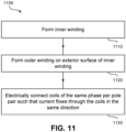
- FIG. 11 illustrates an exemplary method 1100 of forming a double-winding stator, such as stator 400 as described in the foregoing description, according to an embodiment of the present disclosure.
- Method 1100 is suitable for the formation of a double-winding stator for use in a slotless permanent magnet motor having p magnet pole pairs and n phases, where p is an integer greater than zero, and n is an integer ⁇ 3.
- the method 1100 begins at step 1110 in which an inner winding comprising np coils (such as inner winding 960 in FIG. 9B , for example) is formed.
- each winding comprises two layers of wires, each extending longitudinally along the length of the stator, wherein the wires in each winding are arranged immediately next to each other in a sequential order along the span of each winding.
- the method progresses to step 1120 in which the outer winding is wound, such as outer winding 965 in FIG. 9B , for example.
- the outer winding also comprises np coils, arranged on the exterior surface of the inner winding, the coils from each phase in the outer winding circumferentially aligned with the coils from the inner winding having the same phase per pole pair such that each coil of the outer winding also spans 360/( np ) mechanical degrees about the cross section of the double-winding stator.
- each winding comprises two layers of wires, each extending longitudinally along the length of the stator, wherein the wires in each winding are arranged immediately next to each other in a sequential order along the span of each coil.
- the coils of the same phase per pole pair are electrically connected such that current flows through the coils of the same phase in the same direction, step 1130.
Landscapes
- Health & Medical Sciences (AREA)
- Engineering & Computer Science (AREA)
- Heart & Thoracic Surgery (AREA)
- Cardiology (AREA)
- General Health & Medical Sciences (AREA)
- Public Health (AREA)
- Biomedical Technology (AREA)
- Hematology (AREA)
- Life Sciences & Earth Sciences (AREA)
- Animal Behavior & Ethology (AREA)
- Mechanical Engineering (AREA)
- Anesthesiology (AREA)
- Veterinary Medicine (AREA)
- Power Engineering (AREA)
- Vascular Medicine (AREA)
- Manufacturing & Machinery (AREA)
- Transplantation (AREA)
- Windings For Motors And Generators (AREA)
- External Artificial Organs (AREA)
- Structures Of Non-Positive Displacement Pumps (AREA)
Applications Claiming Priority (3)
| Application Number | Priority Date | Filing Date | Title |
|---|---|---|---|
| US201962868530P | 2019-06-28 | 2019-06-28 | |
| EP20740444.3A EP3990047B1 (de) | 2019-06-28 | 2020-06-23 | Intravaskuläre blutpumpe mit mehrschichtigen kernlosen spulen |
| PCT/US2020/039118 WO2020263815A1 (en) | 2019-06-28 | 2020-06-23 | Intravascular blood pump having multilayer coreless coils |
Related Parent Applications (1)
| Application Number | Title | Priority Date | Filing Date |
|---|---|---|---|
| EP20740444.3A Division EP3990047B1 (de) | 2019-06-28 | 2020-06-23 | Intravaskuläre blutpumpe mit mehrschichtigen kernlosen spulen |
Publications (2)
| Publication Number | Publication Date |
|---|---|
| EP4583381A2 true EP4583381A2 (de) | 2025-07-09 |
| EP4583381A3 EP4583381A3 (de) | 2025-08-20 |
Family
ID=71614944
Family Applications (2)
| Application Number | Title | Priority Date | Filing Date |
|---|---|---|---|
| EP25177814.8A Pending EP4583381A3 (de) | 2019-06-28 | 2020-06-23 | Intravaskuläre blutpumpe mit mehrschichtigen kernlosen spulen |
| EP20740444.3A Active EP3990047B1 (de) | 2019-06-28 | 2020-06-23 | Intravaskuläre blutpumpe mit mehrschichtigen kernlosen spulen |
Family Applications After (1)
| Application Number | Title | Priority Date | Filing Date |
|---|---|---|---|
| EP20740444.3A Active EP3990047B1 (de) | 2019-06-28 | 2020-06-23 | Intravaskuläre blutpumpe mit mehrschichtigen kernlosen spulen |
Country Status (13)
| Country | Link |
|---|---|
| US (3) | US11648389B2 (de) |
| EP (2) | EP4583381A3 (de) |
| JP (1) | JP7582983B2 (de) |
| KR (1) | KR20220030269A (de) |
| CN (1) | CN114206429A (de) |
| AU (1) | AU2020301156A1 (de) |
| CA (1) | CA3143977A1 (de) |
| DE (1) | DE112020003119T5 (de) |
| DK (1) | DK3990047T3 (de) |
| ES (1) | ES3036790T3 (de) |
| IL (1) | IL289207B1 (de) |
| TW (2) | TWI879673B (de) |
| WO (1) | WO2020263815A1 (de) |
Families Citing this family (21)
| Publication number | Priority date | Publication date | Assignee | Title |
|---|---|---|---|---|
| DE102018201030B4 (de) | 2018-01-24 | 2025-10-16 | Kardion Gmbh | Magnetkuppelelement mit magnetischer Lagerungsfunktion |
| DE102018207611A1 (de) | 2018-05-16 | 2019-11-21 | Kardion Gmbh | Rotorlagerungssystem |
| DE102018207575A1 (de) | 2018-05-16 | 2019-11-21 | Kardion Gmbh | Magnetische Stirndreh-Kupplung zur Übertragung von Drehmomenten |
| DE102018207594A1 (de) | 2018-05-16 | 2019-11-21 | Kardion Gmbh | Rotor, Magnetkupplungsvorrichtung, Elektromotor für ein Herzunterstützungssystem, Pumpeneinheit für ein Herzunterstützungssystem sowie Verfahren zum Herstellen eines Rotors |
| DE102018208550A1 (de) | 2018-05-30 | 2019-12-05 | Kardion Gmbh | Leitungsvorrichtung zum Leiten eines Blutstroms für ein Herzunterstützungssystem, Herzunterstützungssystem und Verfahren zum Herstellen einer Leitungsvorrichtung |
| DE102018208538A1 (de) | 2018-05-30 | 2019-12-05 | Kardion Gmbh | Intravasale Blutpumpe und Verfahren zur Herstellung von elektrischen Leiterbahnen |
| DE102018208541A1 (de) | 2018-05-30 | 2019-12-05 | Kardion Gmbh | Axialpumpe für ein Herzunterstützungssystem und Verfahren zum Herstellen einer Axialpumpe für ein Herzunterstützungssystem |
| DE102018208549A1 (de) | 2018-05-30 | 2019-12-05 | Kardion Gmbh | Elektronikmodul für ein Herzunterstützungssystem und Verfahren zum Herstellen eines Elektronikmoduls für ein Herzunterstützungssystem |
| DE102018208539A1 (de) | 2018-05-30 | 2019-12-05 | Kardion Gmbh | Motorgehäusemodul zum Abdichten eines Motorraums eines Motors eines Herzunterstützungssystems und Herzunterstützungssystem und Verfahren zum Montieren eines Herzunterstützungssystems |
| DE102018210058A1 (de) | 2018-06-21 | 2019-12-24 | Kardion Gmbh | Statorschaufelvorrichtung zur Strömungsführung eines aus einer Austrittsöffnung eines Herzunterstützungssystems ausströmenden Fluids, Herzunterstützungssystem mit Statorschaufelvorrichtung, Verfahren zum Betreiben einer Statorschaufelvorrichtung und Herstellverfahren |
| DE102018210076A1 (de) | 2018-06-21 | 2019-12-24 | Kardion Gmbh | Verfahren und Vorrichtung zum Erkennen eines Verschleißzustands eines Herzunterstützungssystems, Verfahren und Vorrichtung zum Betreiben eines Herzunterstützungssystems und Herzunterstützungssystem |
| DE102018211297A1 (de) | 2018-07-09 | 2020-01-09 | Kardion Gmbh | Herzunterstützungssystem und Verfahren zur Überwachung der Integrität einer Haltestruktur eines Herzunterstützungssystems |
| DE102018211327A1 (de) | 2018-07-10 | 2020-01-16 | Kardion Gmbh | Laufrad für ein implantierbares, vaskuläres Unterstützungssystem |
| DE102018211328A1 (de) | 2018-07-10 | 2020-01-16 | Kardion Gmbh | Laufradgehäuse für ein implantierbares, vaskuläres Unterstützungssystem |
| DE102018212153A1 (de) | 2018-07-20 | 2020-01-23 | Kardion Gmbh | Zulaufleitung für eine Pumpeneinheit eines Herzunterstützungssystems, Herzunterstützungssystem und Verfahren zum Herstellen einer Zulaufleitung für eine Pumpeneinheit eines Herzunterstützungssystems |
| AU2019320533B2 (en) | 2018-08-07 | 2024-11-21 | Kardion Gmbh | Bearing device for a cardiac support system, and method for flushing an intermediate space in a bearing device for a cardiac support system |
| CN114206429A (zh) * | 2019-06-28 | 2022-03-18 | 阿比奥梅德公司 | 具有多层无芯线圈的血管内血液泵 |
| DE102020102474A1 (de) | 2020-01-31 | 2021-08-05 | Kardion Gmbh | Pumpe zum Fördern eines Fluids und Verfahren zum Herstellen einer Pumpe |
| CA3192451A1 (en) | 2020-09-14 | 2022-03-17 | Johannes Bette | Cardiovascular support pump having an impeller with a variable flow area |
| JP2023550938A (ja) | 2020-11-20 | 2023-12-06 | カルディオン ゲーエムベーハー | ガイドワイヤ補助具付き機械的循環支持システム |
| CN115445078A (zh) * | 2022-08-28 | 2022-12-09 | 上海炫脉医疗科技有限公司 | 一种微型血泵及制造方法 |
Family Cites Families (23)
| Publication number | Priority date | Publication date | Assignee | Title |
|---|---|---|---|---|
| US5850318A (en) * | 1995-06-06 | 1998-12-15 | Seagate Technology, Inc. | Slotless spindle motor for disc drive |
| US5840070A (en) * | 1996-02-20 | 1998-11-24 | Kriton Medical, Inc. | Sealless rotary blood pump |
| AUPO902797A0 (en) * | 1997-09-05 | 1997-10-02 | Cortronix Pty Ltd | A rotary blood pump with hydrodynamically suspended impeller |
| US5928131A (en) * | 1997-11-26 | 1999-07-27 | Vascor, Inc. | Magnetically suspended fluid pump and control system |
| CA2330048C (en) * | 1998-04-22 | 2004-04-20 | University Of Utah | Implantable centrifugal blood pump with hybrid magnetic bearings |
| JPH11341725A (ja) * | 1998-05-21 | 1999-12-10 | Mitsubishi Electric Corp | 永久磁石型モータ |
| DE29921352U1 (de) * | 1999-12-04 | 2001-04-12 | Impella Cardiotechnik AG, 52074 Aachen | Intravasale Blutpumpe |
| JP3906124B2 (ja) * | 2002-07-25 | 2007-04-18 | 本田技研工業株式会社 | 回転機の電機子コイル |
| JP2005287285A (ja) | 2004-03-03 | 2005-10-13 | Asmo Co Ltd | モータ |
| EP1898971B1 (de) * | 2005-06-06 | 2015-03-11 | The Cleveland Clinic Foundation | Blutpumpe |
| JP5284979B2 (ja) | 2006-12-28 | 2013-09-11 | レスメド・モーター・テクノロジーズ・インコーポレーテッド | モーター内のスロットレスステータ用のコイル巻き付け方法及び構造 |
| GB0713864D0 (en) | 2007-07-17 | 2007-08-29 | Sheppard & Charnley Ltd | Electric motor/generator assembly |
| US20120098371A1 (en) * | 2010-10-22 | 2012-04-26 | Spinlectrix Inc. | Stabilization of rotating machinery |
| JP2012253922A (ja) | 2011-06-03 | 2012-12-20 | Seiko Epson Corp | コアレス電気機械装置、移動体、ロボット及びコアレス電気機械装置の製造方法 |
| CN103893849B (zh) | 2014-04-15 | 2016-01-20 | 中南大学 | 一种大气隙磁力驱动的全植入式轴流式血泵及其控制方法 |
| US10177627B2 (en) * | 2015-08-06 | 2019-01-08 | Massachusetts Institute Of Technology | Homopolar, flux-biased hysteresis bearingless motor |
| EP3142228A1 (de) | 2015-09-10 | 2017-03-15 | Siemens Aktiengesellschaft | Stator für eine elektrische maschine, elektrische maschine sowie herstellungsverfahren |
| EP3222301B1 (de) * | 2016-03-23 | 2018-05-09 | Abiomed Europe GmbH | Blutpumpe |
| DE102016220040A1 (de) * | 2016-10-14 | 2018-04-19 | Siemens Aktiengesellschaft | Helixartige Wicklung mit homogenerer Feldausnutzung |
| WO2018139245A1 (ja) | 2017-01-30 | 2018-08-02 | 合同会社IP Bridge1号 | コアレス電気機械装置、コイル用導線、及び、コアレス電気機械装置の製造方法 |
| CN107104570A (zh) * | 2017-07-03 | 2017-08-29 | 中国医学科学院阜外医院 | 一种用于植入式轴流血泵的无槽电机 |
| DE102018217857B4 (de) | 2018-10-18 | 2022-02-03 | Bühler Motor GmbH | Gleichstrommotor und Verfahren zu seiner Herstellung |
| CN114206429A (zh) * | 2019-06-28 | 2022-03-18 | 阿比奥梅德公司 | 具有多层无芯线圈的血管内血液泵 |
-
2020
- 2020-06-23 CN CN202080056866.8A patent/CN114206429A/zh active Pending
- 2020-06-23 JP JP2021577252A patent/JP7582983B2/ja active Active
- 2020-06-23 IL IL289207A patent/IL289207B1/en unknown
- 2020-06-23 DE DE112020003119.5T patent/DE112020003119T5/de active Pending
- 2020-06-23 US US16/909,028 patent/US11648389B2/en active Active
- 2020-06-23 EP EP25177814.8A patent/EP4583381A3/de active Pending
- 2020-06-23 AU AU2020301156A patent/AU2020301156A1/en active Pending
- 2020-06-23 ES ES20740444T patent/ES3036790T3/es active Active
- 2020-06-23 KR KR1020227003126A patent/KR20220030269A/ko active Pending
- 2020-06-23 EP EP20740444.3A patent/EP3990047B1/de active Active
- 2020-06-23 WO PCT/US2020/039118 patent/WO2020263815A1/en not_active Ceased
- 2020-06-23 CA CA3143977A patent/CA3143977A1/en active Pending
- 2020-06-23 DK DK20740444.3T patent/DK3990047T3/da active
- 2020-06-29 TW TW113132659A patent/TWI879673B/zh active
- 2020-06-29 TW TW109121825A patent/TWI857085B/zh active
-
2023
- 2023-04-06 US US18/131,430 patent/US12011583B2/en active Active
-
2024
- 2024-05-09 US US18/659,076 patent/US12364854B2/en active Active
Also Published As
| Publication number | Publication date |
|---|---|
| IL289207A (en) | 2022-02-01 |
| CA3143977A1 (en) | 2020-12-30 |
| AU2020301156A1 (en) | 2022-02-24 |
| TWI879673B (zh) | 2025-04-01 |
| US12364854B2 (en) | 2025-07-22 |
| EP4583381A3 (de) | 2025-08-20 |
| EP3990047A1 (de) | 2022-05-04 |
| JP2025026872A (ja) | 2025-02-26 |
| TW202448545A (zh) | 2024-12-16 |
| IL289207B1 (en) | 2026-04-01 |
| EP3990047B1 (de) | 2025-05-28 |
| US11648389B2 (en) | 2023-05-16 |
| DK3990047T3 (da) | 2025-08-18 |
| US12011583B2 (en) | 2024-06-18 |
| JP7582983B2 (ja) | 2024-11-13 |
| WO2020263815A1 (en) | 2020-12-30 |
| KR20220030269A (ko) | 2022-03-10 |
| DE112020003119T5 (de) | 2022-05-05 |
| US20230310835A1 (en) | 2023-10-05 |
| CN114206429A (zh) | 2022-03-18 |
| US20200405927A1 (en) | 2020-12-31 |
| US20240399136A1 (en) | 2024-12-05 |
| TW202108188A (zh) | 2021-03-01 |
| TWI857085B (zh) | 2024-10-01 |
| ES3036790T3 (en) | 2025-09-24 |
| JP2022539363A (ja) | 2022-09-08 |
Similar Documents
| Publication | Publication Date | Title |
|---|---|---|
| EP3990047B1 (de) | Intravaskuläre blutpumpe mit mehrschichtigen kernlosen spulen | |
| EP3976129B1 (de) | Spulenwickelmuster für erhöhte motoreffizienz | |
| CN117543868A (zh) | 空心杯绕组结构、绕制方法及其经皮介入式血泵 | |
| CN107078579A (zh) | 气隙式绕组 | |
| HK40070450A (en) | Intravascular blood pump having multilayer coreless coils | |
| HK40070450B (en) | Intravascular blood pump having multilayer coreless coils | |
| CN214412445U (zh) | 一种电机定子绕组、电机定子及电机 | |
| AU2020283518B2 (en) | Coil winding pattern for enhanced motor efficiency | |
| HK40068879A (en) | Coil winding pattern for enhanced motor efficiency | |
| HK40068879B (en) | Coil winding pattern for enhanced motor efficiency |
Legal Events
| Date | Code | Title | Description |
|---|---|---|---|
| PUAI | Public reference made under article 153(3) epc to a published international application that has entered the european phase |
Free format text: ORIGINAL CODE: 0009012 |
|
| STAA | Information on the status of an ep patent application or granted ep patent |
Free format text: STATUS: THE APPLICATION HAS BEEN PUBLISHED |
|
| AC | Divisional application: reference to earlier application |
Ref document number: 3990047 Country of ref document: EP Kind code of ref document: P |
|
| AK | Designated contracting states |
Kind code of ref document: A2 Designated state(s): AL AT BE BG CH CY CZ DE DK EE ES FI FR GB GR HR HU IE IS IT LI LT LU LV MC MK MT NL NO PL PT RO RS SE SI SK SM TR |
|
| REG | Reference to a national code |
Ref country code: DE Ref legal event code: R079 Free format text: PREVIOUS MAIN CLASS: H02K0021140000 Ipc: A61M0060130000 |
|
| PUAL | Search report despatched |
Free format text: ORIGINAL CODE: 0009013 |
|
| AK | Designated contracting states |
Kind code of ref document: A3 Designated state(s): AL AT BE BG CH CY CZ DE DK EE ES FI FR GB GR HR HU IE IS IT LI LT LU LV MC MK MT NL NO PL PT RO RS SE SI SK SM TR |
|
| RIC1 | Information provided on ipc code assigned before grant |
Ipc: A61M 60/13 20210101AFI20250715BHEP Ipc: A61M 60/237 20210101ALI20250715BHEP Ipc: A61M 60/416 20210101ALI20250715BHEP Ipc: A61M 60/508 20210101ALI20250715BHEP Ipc: H02K 1/27 20220101ALI20250715BHEP Ipc: H02K 3/04 20060101ALI20250715BHEP Ipc: H02K 3/28 20060101ALI20250715BHEP Ipc: H02K 3/47 20060101ALI20250715BHEP Ipc: H02K 7/14 20060101ALI20250715BHEP Ipc: H02K 15/04 20250101ALI20250715BHEP Ipc: H02K 21/14 20060101ALI20250715BHEP Ipc: H02K 15/043 20250101ALI20250715BHEP Ipc: H02K 1/278 20220101ALI20250715BHEP |
|
| P01 | Opt-out of the competence of the unified patent court (upc) registered |
Free format text: CASE NUMBER: UPC_APP_5541_4583381/2025 Effective date: 20250901 |
|
| STAA | Information on the status of an ep patent application or granted ep patent |
Free format text: STATUS: REQUEST FOR EXAMINATION WAS MADE |
|
| 17P | Request for examination filed |
Effective date: 20260220 |