EP4583232A1 - Energiespeichervorrichtung, elektrische vorrichtung und wickelverfahren - Google Patents
Energiespeichervorrichtung, elektrische vorrichtung und wickelverfahren Download PDFInfo
- Publication number
- EP4583232A1 EP4583232A1 EP22964893.6A EP22964893A EP4583232A1 EP 4583232 A1 EP4583232 A1 EP 4583232A1 EP 22964893 A EP22964893 A EP 22964893A EP 4583232 A1 EP4583232 A1 EP 4583232A1
- Authority
- EP
- European Patent Office
- Prior art keywords
- tab
- electrode
- width
- energy
- storage device
- Prior art date
- Legal status (The legal status is an assumption and is not a legal conclusion. Google has not performed a legal analysis and makes no representation as to the accuracy of the status listed.)
- Pending
Links
Images



Classifications
-
- H—ELECTRICITY
- H01—ELECTRIC ELEMENTS
- H01M—PROCESSES OR MEANS, e.g. BATTERIES, FOR THE DIRECT CONVERSION OF CHEMICAL ENERGY INTO ELECTRICAL ENERGY
- H01M50/00—Constructional details or processes of manufacture of the non-active parts of electrochemical cells other than fuel cells, e.g. hybrid cells
- H01M50/10—Primary casings; Jackets or wrappings
- H01M50/147—Lids or covers
- H01M50/148—Lids or covers characterised by their shape
- H01M50/15—Lids or covers characterised by their shape for prismatic or rectangular cells
-
- H—ELECTRICITY
- H01—ELECTRIC ELEMENTS
- H01M—PROCESSES OR MEANS, e.g. BATTERIES, FOR THE DIRECT CONVERSION OF CHEMICAL ENERGY INTO ELECTRICAL ENERGY
- H01M10/00—Secondary cells; Manufacture thereof
- H01M10/04—Construction or manufacture in general
- H01M10/0404—Machines for assembling batteries
- H01M10/0409—Machines for assembling batteries for cells with wound electrodes
-
- H—ELECTRICITY
- H01—ELECTRIC ELEMENTS
- H01M—PROCESSES OR MEANS, e.g. BATTERIES, FOR THE DIRECT CONVERSION OF CHEMICAL ENERGY INTO ELECTRICAL ENERGY
- H01M10/00—Secondary cells; Manufacture thereof
- H01M10/05—Accumulators with non-aqueous electrolyte
- H01M10/052—Li-accumulators
- H01M10/0525—Rocking-chair batteries, i.e. batteries with lithium insertion or intercalation in both electrodes; Lithium-ion batteries
-
- H—ELECTRICITY
- H01—ELECTRIC ELEMENTS
- H01M—PROCESSES OR MEANS, e.g. BATTERIES, FOR THE DIRECT CONVERSION OF CHEMICAL ENERGY INTO ELECTRICAL ENERGY
- H01M10/00—Secondary cells; Manufacture thereof
- H01M10/05—Accumulators with non-aqueous electrolyte
- H01M10/058—Construction or manufacture
- H01M10/0587—Construction or manufacture of accumulators having only wound construction elements, i.e. wound positive electrodes, wound negative electrodes and wound separators
-
- H—ELECTRICITY
- H01—ELECTRIC ELEMENTS
- H01M—PROCESSES OR MEANS, e.g. BATTERIES, FOR THE DIRECT CONVERSION OF CHEMICAL ENERGY INTO ELECTRICAL ENERGY
- H01M50/00—Constructional details or processes of manufacture of the non-active parts of electrochemical cells other than fuel cells, e.g. hybrid cells
- H01M50/50—Current conducting connections for cells or batteries
- H01M50/528—Fixed electrical connections, i.e. not intended for disconnection
-
- H—ELECTRICITY
- H01—ELECTRIC ELEMENTS
- H01M—PROCESSES OR MEANS, e.g. BATTERIES, FOR THE DIRECT CONVERSION OF CHEMICAL ENERGY INTO ELECTRICAL ENERGY
- H01M50/00—Constructional details or processes of manufacture of the non-active parts of electrochemical cells other than fuel cells, e.g. hybrid cells
- H01M50/50—Current conducting connections for cells or batteries
- H01M50/531—Electrode connections inside a battery casing
- H01M50/533—Electrode connections inside a battery casing characterised by the shape of the leads or tabs
-
- H—ELECTRICITY
- H01—ELECTRIC ELEMENTS
- H01M—PROCESSES OR MEANS, e.g. BATTERIES, FOR THE DIRECT CONVERSION OF CHEMICAL ENERGY INTO ELECTRICAL ENERGY
- H01M50/00—Constructional details or processes of manufacture of the non-active parts of electrochemical cells other than fuel cells, e.g. hybrid cells
- H01M50/50—Current conducting connections for cells or batteries
- H01M50/531—Electrode connections inside a battery casing
- H01M50/536—Electrode connections inside a battery casing characterised by the method of fixing the leads to the electrodes, e.g. by welding
-
- Y—GENERAL TAGGING OF NEW TECHNOLOGICAL DEVELOPMENTS; GENERAL TAGGING OF CROSS-SECTIONAL TECHNOLOGIES SPANNING OVER SEVERAL SECTIONS OF THE IPC; TECHNICAL SUBJECTS COVERED BY FORMER USPC CROSS-REFERENCE ART COLLECTIONS [XRACs] AND DIGESTS
- Y02—TECHNOLOGIES OR APPLICATIONS FOR MITIGATION OR ADAPTATION AGAINST CLIMATE CHANGE
- Y02E—REDUCTION OF GREENHOUSE GAS [GHG] EMISSIONS, RELATED TO ENERGY GENERATION, TRANSMISSION OR DISTRIBUTION
- Y02E60/00—Enabling technologies; Technologies with a potential or indirect contribution to GHG emissions mitigation
- Y02E60/10—Energy storage using batteries
-
- Y—GENERAL TAGGING OF NEW TECHNOLOGICAL DEVELOPMENTS; GENERAL TAGGING OF CROSS-SECTIONAL TECHNOLOGIES SPANNING OVER SEVERAL SECTIONS OF THE IPC; TECHNICAL SUBJECTS COVERED BY FORMER USPC CROSS-REFERENCE ART COLLECTIONS [XRACs] AND DIGESTS
- Y02—TECHNOLOGIES OR APPLICATIONS FOR MITIGATION OR ADAPTATION AGAINST CLIMATE CHANGE
- Y02P—CLIMATE CHANGE MITIGATION TECHNOLOGIES IN THE PRODUCTION OR PROCESSING OF GOODS
- Y02P70/00—Climate change mitigation technologies in the production process for final industrial or consumer products
- Y02P70/50—Manufacturing or production processes characterised by the final manufactured product
Definitions
- This disclosure relates to the field of energy storage, and in particular, to an energy-storage device, an electrical apparatus, and a winding method.
- an energy-storage device an electrical apparatus, and a winding method are provided in the disclosure to solve the technical problems mentioned above.
- the energy-storage device includes an electrode and a separator, where the electrode and the separator are stacked and wound to form a cell.
- the electrode is connected with a tab at an end of the electrode in a width direction of the electrode, where the tab includes a first tab and a second tab.
- the first tab is positioned adjacent to an end of the electrode in a length direction of the electrode, and the first tab defines a U-shaped notch.
- the electrical apparatus includes at least one energy-storage device mentioned above, where the energy-storage device is configured to power the electrical apparatus.
- a winding method is provided in a third aspect of the disclosure.
- the winding method is for manufacturing the energy-storage device in the first aspect and begins with operations at step 1.
- the electrode and the separator stacked with the electrode are placed in a winding machine, and the electrode and the separator are wound by the winding machine.
- a sensor of the winding machine senses the U-shaped notch of the first tab and a position of the first tab is determined.
- the electrode is cut at a position close to the first tab in the length direction of the electrode to end winding.
- the first tab defines the U-shaped notch.
- a winding end position of the cell is marked as the U-shaped notch, and the winding end position is determined according to the U-shaped notch in a process that the electrode is wound to form the cell.
- the winding end position of the cell is recognized by recognizing the U-shaped notch, and the electrode is cut at the position close to the first tab to end winding, thus it is unnecessary to determine manually the winding end position, thereby realizing winding automation.
- the terms “first”, “second”, and the like used in the specification, the claims, and the accompany drawings of the disclosure are used to distinguish different objects rather than describe a particular order.
- the words “one”, “a”, “the”, and similar words used in the disclosure do not indicate a numerical limitation but are only used to indicate existence of at least one.
- the words “includes”, “contains”, and similar words are intended to mean that an element or object preceding the word covers an element, object, or the equivalent appearing after the word, without excluding other elements or objects.
- the words “connected”, “coupled”, or similar words are not limited to physical or mechanical connections and may include electrical connections, whether direct or indirect.
- an implementation means that a particular feature, structure, material, or characteristic described in conjunction with the implementations or embodiments may be contained in at least one implementation or embodiment of the disclosure.
- the exemplary expressions of the above terms appearing in the specification does not necessarily refer to the same implementation or embodiment.
- the particular feature, structure, material, or characteristic described may be properly combined in any one or more implementations or embodiments.
- An energy-storage device in the disclosure may be a battery, or may also be battery modules including batteries, a battery pack, a battery cluster, or other devices with an electricity-energy storage function.
- a battery 3 illustrated in FIG. 1 will be described as follows.
- the end of the electrode 10 in the length direction L of the electrode 10 is denoted as a winding end position of the electrode 10 during winding.
- the winding end position of the electrode 10 can be determined through the U-shaped notch 130 of the first tab 13 during winding to execute corresponding control operations, thereby realizing winding automation.
- the width direction W and the length direction L are defined.
- the electrode 10 is in a long strip shape and has a length excessively longer than a width of the electrode 10.
- the width direction W is a width direction of the electrode 10
- the length direction L is a length direction of the electrode 10.
- the first tab 13 has a first end 131 away from the electrode 10, and the U-shaped notch 130 extends from the first end 131 toward the electrode 10 by cutting.
- the U-shaped notch 130 has a width extending in the length direction L of the electrode 10 and a depth extending in the width direction W of the electrode 10, where a ratio of the width to the depth of the U-shaped notch 130 is greater than 1.5 and less than 2.
- the U-shaped notch 130 It is easier for the U-shaped notch 130 to extend in a direction of the depth of the U-shaped notch 130 than in a direction of the width of the U-shaped notch 130, and therefore the ratio of the width to the depth of the U-shaped notch 130 is limited to be greater than 1.5 and less than 2 in the disclosure.
- the ratio of the width to the depth of the U-shaped notch 130 is limited to be greater than 1.5 and less than 2 in the disclosure.
- a type of the first tab 13 may be chosen according to actual production needs.
- FIG. 7 illustrates a schematic structural diagram illustrating a first tab in a fourth implementation of the disclosure.
- the first tab 13 defines a wave notch 132 in the fourth implementation.
- the wave notch 132 also has strong identification to enable the first tab 13 to be clearly distinguished from the second tab 12, and the wave notch 132 is easy and simple to be processed. Thus it is possible to improve identification accuracy and is convenient to process the first tab 13 through the wave notch 132.
- FIG. 8 illustrates a schematic structural diagram illustrating a first tab in a fifth implementation of the disclosure.
- the first tab 13 defines a square wave notch 133 in the fifth implementation.
- the square wave notch 133 also has strong identification to enable the first tab 13 to be clearly distinguished from the second tab 12, and the square wave notch 133 is easy and simple to be processed. Thus it is possible to improve identification accuracy and is convenient to process the first tab 13 through the square wave notch 133.
- FIG. 9 illustrates a schematic structural diagram illustrating a first tab in a sixth implementation of the disclosure.
- the first tab 13 defines a bevel notch 134 at an end.
- the bevel notch 134 also has strong identification to enable the first tab 13 to be clearly distinguished from the second tab 12, and the bevel notch 134 is easy and simple to be processed. Thus it is possible to improve identification accuracy and is convenient to process the first tab 13 through the bevel notch 134.
- the first tab 13 may also define a semi-circular notch, or the like, in other implementations.
- the first tab 13 may also define one of an injection-molded serrated notch, a wave notch, a square wave notch, or a semi-circular notch or a combination thereof, in other implementations.
- the first tab 13 is provided with an indentation with identification information in other implementations, where the identification information may be, but is not limited to, one of a square pattern, an oval pattern, a heart-shaped pattern, a trapezoidal pattern, or a specific pattern or a combination thereof.
- the first tab 13 is provided with the indentation with the identification information, so that no metal particle falls and no burr is generated during processing of the first tab 13. Thus it is possible to avoid lots of secondary hazards and greatly improve a safety factor. Furthermore, the indentation on the first tab 13 enables that an apparatus is able to determine automatically a winding end position, thereby realizing winding automation.
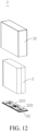
- the electrode 10 is wound to form the roll core, multiple tabs 11 are stacked and bent from the tab root 110 to be approximately parallel to an end surface of the roll core, and the adaptor piece 320 attached to the multiple tabs 11 is welded with the multiple tabs 11.
- the housing 31 is one of an aluminum housing, a steel housing, a stainless steel housing, or the like.
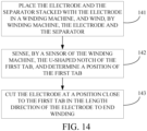
- FIG. 14 is a schematic flow chart illustrating a winding method in an implementation of the disclosure.
- the winding method is for manufacturing the energy-storage device mentioned above and includes the following.
- the electrode 10 and the separator stacked with the electrode 10 are placed in a winding machine, and the electrode 10 and the separator are wound by the winding machine.
- a sensor of the winding machine senses the U-shaped notch 130 of the first tab 13 and a position of the first tab 13 is determined.
- the first tab 13 defines the U-shaped notch 130.
- a winding end position of the cell 1 is marked as the U-shaped notch 130, and the winding end position is determined according to the U-shaped notch 130 in a process that the electrode 10 is wound to form the cell 1.
- the winding end position of the cell 1 is recognized by recognizing the U-shaped notch 130, and the electrode 10 is cut at the position close to the first tab 13 to end winding. Thus it is unnecessary to determine manually the winding end position, thereby realizing winding automation.
Landscapes
- Chemical & Material Sciences (AREA)
- Chemical Kinetics & Catalysis (AREA)
- Electrochemistry (AREA)
- General Chemical & Material Sciences (AREA)
- Engineering & Computer Science (AREA)
- Manufacturing & Machinery (AREA)
- Materials Engineering (AREA)
- Connection Of Batteries Or Terminals (AREA)
- Secondary Cells (AREA)
Applications Claiming Priority (1)
| Application Number | Priority Date | Filing Date | Title |
|---|---|---|---|
| PCT/CN2022/131549 WO2024098425A1 (zh) | 2022-11-11 | 2022-11-11 | 储能装置、用电设备以及卷绕方法 |
Publications (2)
| Publication Number | Publication Date |
|---|---|
| EP4583232A1 true EP4583232A1 (de) | 2025-07-09 |
| EP4583232A4 EP4583232A4 (de) | 2026-01-21 |
Family
ID=91031804
Family Applications (1)
| Application Number | Title | Priority Date | Filing Date |
|---|---|---|---|
| EP22964893.6A Pending EP4583232A4 (de) | 2022-11-11 | 2022-11-11 | Energiespeichervorrichtung, elektrische vorrichtung und wickelverfahren |
Country Status (2)
| Country | Link |
|---|---|
| EP (1) | EP4583232A4 (de) |
| WO (1) | WO2024098425A1 (de) |
Family Cites Families (9)
| Publication number | Priority date | Publication date | Assignee | Title |
|---|---|---|---|---|
| JP2005122940A (ja) * | 2003-10-14 | 2005-05-12 | Matsushita Electric Ind Co Ltd | 電池及びその製造方法 |
| CN102916226B (zh) * | 2012-09-20 | 2016-06-22 | 东莞新能源科技有限公司 | 方型动力锂离子电池的卷绕方法 |
| JP6357776B2 (ja) * | 2014-01-06 | 2018-07-18 | 株式会社ジェイテクト | 蓄電デバイスの製造方法 |
| KR102106109B1 (ko) * | 2016-01-25 | 2020-04-29 | 주식회사 엘지화학 | 리튬이차전지 |
| EP3902046A4 (de) * | 2018-12-19 | 2022-03-02 | SANYO Electric Co., Ltd. | Sekundärbatterie und herstellungsverfahren dafür |
| US20230223658A1 (en) * | 2020-06-19 | 2023-07-13 | Varta Microbattery Gmbh | Lithium-ion cell with a high specific energy density |
| CA3202317A1 (en) * | 2021-01-19 | 2022-07-28 | Lg Energy Solution, Ltd. | Battery and current collector applied thereto, and battery pack and vehicle including the same |
| CN216450703U (zh) * | 2021-10-19 | 2022-05-06 | 厦门海辰新能源科技有限公司 | 一种二次电池的电芯及二次电池 |
| CN217134453U (zh) * | 2022-04-21 | 2022-08-05 | 合肥国轩高科动力能源有限公司 | 一种单隔膜叠片电芯单元及叠片电芯结构 |
-
2022
- 2022-11-11 WO PCT/CN2022/131549 patent/WO2024098425A1/zh not_active Ceased
- 2022-11-11 EP EP22964893.6A patent/EP4583232A4/de active Pending
Also Published As
| Publication number | Publication date |
|---|---|
| WO2024098425A1 (zh) | 2024-05-16 |
| EP4583232A4 (de) | 2026-01-21 |
Similar Documents
| Publication | Publication Date | Title |
|---|---|---|
| EP3051610B1 (de) | Elektrodenanordnung und wiederaufladbare batterie mit elektrodenlasche | |
| US11450932B2 (en) | Battery, preparation method thereof and electric device | |
| US20240088527A1 (en) | Battery and portable electrical device | |
| EP4333099A1 (de) | Batterieelektrodenplatte, batterie und verfahren zur herstellung einer batterieelektrodenplatte | |
| JP2014022116A (ja) | 二次電池用極板及び二次電池用極板の製造方法 | |
| US12191530B2 (en) | Energy-storage device, electrical apparatus, and winding method | |
| CN115458879A (zh) | 电芯及电芯制造方法 | |
| US20240222817A1 (en) | Battery, manufacturing method thereof and electronic product | |
| JP4438784B2 (ja) | 蓄電装置 | |
| US9059460B2 (en) | Prismatic secondary battery | |
| KR102368090B1 (ko) | 전극탭을 갖는 전극 어셈블리 및 이차 전지 | |
| EP4679513A1 (de) | Sekundärbatterie, batterieanordnung und elektronische vorrichtung | |
| EP3226338A1 (de) | Wickelzelle | |
| EP4203151A1 (de) | Vorrichtung und verfahren zur überprüfung der fehlmontage einer batteriezellenaktivierungsschale oder verdrehung davon während des betriebs | |
| CN115425365A (zh) | 集流组件、电池、电池包及用电设备 | |
| CN207441856U (zh) | 极片及电极组件 | |
| EP4583232A1 (de) | Energiespeichervorrichtung, elektrische vorrichtung und wickelverfahren | |
| CN218385635U (zh) | 电极片、电芯及扣式电池 | |
| JP2019029189A (ja) | 角形二次電池及びそれを用いた組電池 | |
| CN208570816U (zh) | 便于注液的圆柱形锂离子端面焊电池 | |
| JP2003272598A (ja) | 非水電解液電池およびその製造方法 | |
| CN114976512A (zh) | 极片、电芯结构、锂电池以及电子设备 | |
| CN217903145U (zh) | 一种极片和电池 | |
| CN218385268U (zh) | 电极片、电芯及扣式电池 | |
| CN224005883U (zh) | 一种全极耳极片及圆柱锂离子电池 |
Legal Events
| Date | Code | Title | Description |
|---|---|---|---|
| STAA | Information on the status of an ep patent application or granted ep patent |
Free format text: STATUS: THE INTERNATIONAL PUBLICATION HAS BEEN MADE |
|
| PUAI | Public reference made under article 153(3) epc to a published international application that has entered the european phase |
Free format text: ORIGINAL CODE: 0009012 |
|
| STAA | Information on the status of an ep patent application or granted ep patent |
Free format text: STATUS: REQUEST FOR EXAMINATION WAS MADE |
|
| 17P | Request for examination filed |
Effective date: 20250401 |
|
| AK | Designated contracting states |
Kind code of ref document: A1 Designated state(s): AL AT BE BG CH CY CZ DE DK EE ES FI FR GB GR HR HU IE IS IT LI LT LU LV MC ME MK MT NL NO PL PT RO RS SE SI SK SM TR |
|
| A4 | Supplementary search report drawn up and despatched |
Effective date: 20251219 |
|
| RIC1 | Information provided on ipc code assigned before grant |
Ipc: H01M 10/0583 20100101AFI20251215BHEP Ipc: H01M 10/052 20100101ALI20251215BHEP Ipc: H01M 50/538 20210101ALI20251215BHEP Ipc: H01M 50/533 20210101ALI20251215BHEP Ipc: H01M 10/04 20060101ALI20251215BHEP Ipc: H01M 10/0587 20100101ALI20251215BHEP Ipc: H01M 50/15 20210101ALI20251215BHEP Ipc: H01M 50/528 20210101ALI20251215BHEP Ipc: H01M 10/0525 20100101ALI20251215BHEP Ipc: H01M 50/536 20210101ALI20251215BHEP |
|
| DAV | Request for validation of the european patent (deleted) | ||
| DAX | Request for extension of the european patent (deleted) |