EP4583232A1 - Energy storage apparatus, electric device, and winding method - Google Patents
Energy storage apparatus, electric device, and winding method Download PDFInfo
- Publication number
- EP4583232A1 EP4583232A1 EP22964893.6A EP22964893A EP4583232A1 EP 4583232 A1 EP4583232 A1 EP 4583232A1 EP 22964893 A EP22964893 A EP 22964893A EP 4583232 A1 EP4583232 A1 EP 4583232A1
- Authority
- EP
- European Patent Office
- Prior art keywords
- tab
- electrode
- width
- energy
- storage device
- Prior art date
- Legal status (The legal status is an assumption and is not a legal conclusion. Google has not performed a legal analysis and makes no representation as to the accuracy of the status listed.)
- Pending
Links
Images



Classifications
-
- H—ELECTRICITY
- H01—ELECTRIC ELEMENTS
- H01M—PROCESSES OR MEANS, e.g. BATTERIES, FOR THE DIRECT CONVERSION OF CHEMICAL ENERGY INTO ELECTRICAL ENERGY
- H01M50/00—Constructional details or processes of manufacture of the non-active parts of electrochemical cells other than fuel cells, e.g. hybrid cells
- H01M50/10—Primary casings; Jackets or wrappings
- H01M50/147—Lids or covers
- H01M50/148—Lids or covers characterised by their shape
- H01M50/15—Lids or covers characterised by their shape for prismatic or rectangular cells
-
- H—ELECTRICITY
- H01—ELECTRIC ELEMENTS
- H01M—PROCESSES OR MEANS, e.g. BATTERIES, FOR THE DIRECT CONVERSION OF CHEMICAL ENERGY INTO ELECTRICAL ENERGY
- H01M10/00—Secondary cells; Manufacture thereof
- H01M10/04—Construction or manufacture in general
- H01M10/0404—Machines for assembling batteries
- H01M10/0409—Machines for assembling batteries for cells with wound electrodes
-
- H—ELECTRICITY
- H01—ELECTRIC ELEMENTS
- H01M—PROCESSES OR MEANS, e.g. BATTERIES, FOR THE DIRECT CONVERSION OF CHEMICAL ENERGY INTO ELECTRICAL ENERGY
- H01M10/00—Secondary cells; Manufacture thereof
- H01M10/05—Accumulators with non-aqueous electrolyte
- H01M10/052—Li-accumulators
- H01M10/0525—Rocking-chair batteries, i.e. batteries with lithium insertion or intercalation in both electrodes; Lithium-ion batteries
-
- H—ELECTRICITY
- H01—ELECTRIC ELEMENTS
- H01M—PROCESSES OR MEANS, e.g. BATTERIES, FOR THE DIRECT CONVERSION OF CHEMICAL ENERGY INTO ELECTRICAL ENERGY
- H01M10/00—Secondary cells; Manufacture thereof
- H01M10/05—Accumulators with non-aqueous electrolyte
- H01M10/058—Construction or manufacture
- H01M10/0587—Construction or manufacture of accumulators having only wound construction elements, i.e. wound positive electrodes, wound negative electrodes and wound separators
-
- H—ELECTRICITY
- H01—ELECTRIC ELEMENTS
- H01M—PROCESSES OR MEANS, e.g. BATTERIES, FOR THE DIRECT CONVERSION OF CHEMICAL ENERGY INTO ELECTRICAL ENERGY
- H01M50/00—Constructional details or processes of manufacture of the non-active parts of electrochemical cells other than fuel cells, e.g. hybrid cells
- H01M50/50—Current conducting connections for cells or batteries
- H01M50/528—Fixed electrical connections, i.e. not intended for disconnection
-
- H—ELECTRICITY
- H01—ELECTRIC ELEMENTS
- H01M—PROCESSES OR MEANS, e.g. BATTERIES, FOR THE DIRECT CONVERSION OF CHEMICAL ENERGY INTO ELECTRICAL ENERGY
- H01M50/00—Constructional details or processes of manufacture of the non-active parts of electrochemical cells other than fuel cells, e.g. hybrid cells
- H01M50/50—Current conducting connections for cells or batteries
- H01M50/531—Electrode connections inside a battery casing
- H01M50/533—Electrode connections inside a battery casing characterised by the shape of the leads or tabs
-
- H—ELECTRICITY
- H01—ELECTRIC ELEMENTS
- H01M—PROCESSES OR MEANS, e.g. BATTERIES, FOR THE DIRECT CONVERSION OF CHEMICAL ENERGY INTO ELECTRICAL ENERGY
- H01M50/00—Constructional details or processes of manufacture of the non-active parts of electrochemical cells other than fuel cells, e.g. hybrid cells
- H01M50/50—Current conducting connections for cells or batteries
- H01M50/531—Electrode connections inside a battery casing
- H01M50/536—Electrode connections inside a battery casing characterised by the method of fixing the leads to the electrodes, e.g. by welding
-
- Y—GENERAL TAGGING OF NEW TECHNOLOGICAL DEVELOPMENTS; GENERAL TAGGING OF CROSS-SECTIONAL TECHNOLOGIES SPANNING OVER SEVERAL SECTIONS OF THE IPC; TECHNICAL SUBJECTS COVERED BY FORMER USPC CROSS-REFERENCE ART COLLECTIONS [XRACs] AND DIGESTS
- Y02—TECHNOLOGIES OR APPLICATIONS FOR MITIGATION OR ADAPTATION AGAINST CLIMATE CHANGE
- Y02E—REDUCTION OF GREENHOUSE GAS [GHG] EMISSIONS, RELATED TO ENERGY GENERATION, TRANSMISSION OR DISTRIBUTION
- Y02E60/00—Enabling technologies; Technologies with a potential or indirect contribution to GHG emissions mitigation
- Y02E60/10—Energy storage using batteries
-
- Y—GENERAL TAGGING OF NEW TECHNOLOGICAL DEVELOPMENTS; GENERAL TAGGING OF CROSS-SECTIONAL TECHNOLOGIES SPANNING OVER SEVERAL SECTIONS OF THE IPC; TECHNICAL SUBJECTS COVERED BY FORMER USPC CROSS-REFERENCE ART COLLECTIONS [XRACs] AND DIGESTS
- Y02—TECHNOLOGIES OR APPLICATIONS FOR MITIGATION OR ADAPTATION AGAINST CLIMATE CHANGE
- Y02P—CLIMATE CHANGE MITIGATION TECHNOLOGIES IN THE PRODUCTION OR PROCESSING OF GOODS
- Y02P70/00—Climate change mitigation technologies in the production process for final industrial or consumer products
- Y02P70/50—Manufacturing or production processes characterised by the final manufactured product
Definitions
- This disclosure relates to the field of energy storage, and in particular, to an energy-storage device, an electrical apparatus, and a winding method.
- an energy-storage device an electrical apparatus, and a winding method are provided in the disclosure to solve the technical problems mentioned above.
- the energy-storage device includes an electrode and a separator, where the electrode and the separator are stacked and wound to form a cell.
- the electrode is connected with a tab at an end of the electrode in a width direction of the electrode, where the tab includes a first tab and a second tab.
- the first tab is positioned adjacent to an end of the electrode in a length direction of the electrode, and the first tab defines a U-shaped notch.
- the electrical apparatus includes at least one energy-storage device mentioned above, where the energy-storage device is configured to power the electrical apparatus.
- a winding method is provided in a third aspect of the disclosure.
- the winding method is for manufacturing the energy-storage device in the first aspect and begins with operations at step 1.
- the electrode and the separator stacked with the electrode are placed in a winding machine, and the electrode and the separator are wound by the winding machine.
- a sensor of the winding machine senses the U-shaped notch of the first tab and a position of the first tab is determined.
- the electrode is cut at a position close to the first tab in the length direction of the electrode to end winding.
- the first tab defines the U-shaped notch.
- a winding end position of the cell is marked as the U-shaped notch, and the winding end position is determined according to the U-shaped notch in a process that the electrode is wound to form the cell.
- the winding end position of the cell is recognized by recognizing the U-shaped notch, and the electrode is cut at the position close to the first tab to end winding, thus it is unnecessary to determine manually the winding end position, thereby realizing winding automation.
- the terms “first”, “second”, and the like used in the specification, the claims, and the accompany drawings of the disclosure are used to distinguish different objects rather than describe a particular order.
- the words “one”, “a”, “the”, and similar words used in the disclosure do not indicate a numerical limitation but are only used to indicate existence of at least one.
- the words “includes”, “contains”, and similar words are intended to mean that an element or object preceding the word covers an element, object, or the equivalent appearing after the word, without excluding other elements or objects.
- the words “connected”, “coupled”, or similar words are not limited to physical or mechanical connections and may include electrical connections, whether direct or indirect.
- an implementation means that a particular feature, structure, material, or characteristic described in conjunction with the implementations or embodiments may be contained in at least one implementation or embodiment of the disclosure.
- the exemplary expressions of the above terms appearing in the specification does not necessarily refer to the same implementation or embodiment.
- the particular feature, structure, material, or characteristic described may be properly combined in any one or more implementations or embodiments.
- An energy-storage device in the disclosure may be a battery, or may also be battery modules including batteries, a battery pack, a battery cluster, or other devices with an electricity-energy storage function.
- a battery 3 illustrated in FIG. 1 will be described as follows.
- the end of the electrode 10 in the length direction L of the electrode 10 is denoted as a winding end position of the electrode 10 during winding.
- the winding end position of the electrode 10 can be determined through the U-shaped notch 130 of the first tab 13 during winding to execute corresponding control operations, thereby realizing winding automation.
- the width direction W and the length direction L are defined.
- the electrode 10 is in a long strip shape and has a length excessively longer than a width of the electrode 10.
- the width direction W is a width direction of the electrode 10
- the length direction L is a length direction of the electrode 10.
- the first tab 13 has a first end 131 away from the electrode 10, and the U-shaped notch 130 extends from the first end 131 toward the electrode 10 by cutting.
- the U-shaped notch 130 has a width extending in the length direction L of the electrode 10 and a depth extending in the width direction W of the electrode 10, where a ratio of the width to the depth of the U-shaped notch 130 is greater than 1.5 and less than 2.
- the U-shaped notch 130 It is easier for the U-shaped notch 130 to extend in a direction of the depth of the U-shaped notch 130 than in a direction of the width of the U-shaped notch 130, and therefore the ratio of the width to the depth of the U-shaped notch 130 is limited to be greater than 1.5 and less than 2 in the disclosure.
- the ratio of the width to the depth of the U-shaped notch 130 is limited to be greater than 1.5 and less than 2 in the disclosure.
- a type of the first tab 13 may be chosen according to actual production needs.
- FIG. 7 illustrates a schematic structural diagram illustrating a first tab in a fourth implementation of the disclosure.
- the first tab 13 defines a wave notch 132 in the fourth implementation.
- the wave notch 132 also has strong identification to enable the first tab 13 to be clearly distinguished from the second tab 12, and the wave notch 132 is easy and simple to be processed. Thus it is possible to improve identification accuracy and is convenient to process the first tab 13 through the wave notch 132.
- FIG. 8 illustrates a schematic structural diagram illustrating a first tab in a fifth implementation of the disclosure.
- the first tab 13 defines a square wave notch 133 in the fifth implementation.
- the square wave notch 133 also has strong identification to enable the first tab 13 to be clearly distinguished from the second tab 12, and the square wave notch 133 is easy and simple to be processed. Thus it is possible to improve identification accuracy and is convenient to process the first tab 13 through the square wave notch 133.
- FIG. 9 illustrates a schematic structural diagram illustrating a first tab in a sixth implementation of the disclosure.
- the first tab 13 defines a bevel notch 134 at an end.
- the bevel notch 134 also has strong identification to enable the first tab 13 to be clearly distinguished from the second tab 12, and the bevel notch 134 is easy and simple to be processed. Thus it is possible to improve identification accuracy and is convenient to process the first tab 13 through the bevel notch 134.
- the first tab 13 may also define a semi-circular notch, or the like, in other implementations.
- the first tab 13 may also define one of an injection-molded serrated notch, a wave notch, a square wave notch, or a semi-circular notch or a combination thereof, in other implementations.
- the first tab 13 is provided with an indentation with identification information in other implementations, where the identification information may be, but is not limited to, one of a square pattern, an oval pattern, a heart-shaped pattern, a trapezoidal pattern, or a specific pattern or a combination thereof.
- the first tab 13 is provided with the indentation with the identification information, so that no metal particle falls and no burr is generated during processing of the first tab 13. Thus it is possible to avoid lots of secondary hazards and greatly improve a safety factor. Furthermore, the indentation on the first tab 13 enables that an apparatus is able to determine automatically a winding end position, thereby realizing winding automation.
- the electrode 10 is wound to form the roll core, multiple tabs 11 are stacked and bent from the tab root 110 to be approximately parallel to an end surface of the roll core, and the adaptor piece 320 attached to the multiple tabs 11 is welded with the multiple tabs 11.
- the housing 31 is one of an aluminum housing, a steel housing, a stainless steel housing, or the like.
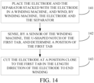
- FIG. 14 is a schematic flow chart illustrating a winding method in an implementation of the disclosure.
- the winding method is for manufacturing the energy-storage device mentioned above and includes the following.
- the electrode 10 and the separator stacked with the electrode 10 are placed in a winding machine, and the electrode 10 and the separator are wound by the winding machine.
- a sensor of the winding machine senses the U-shaped notch 130 of the first tab 13 and a position of the first tab 13 is determined.
- the first tab 13 defines the U-shaped notch 130.
- a winding end position of the cell 1 is marked as the U-shaped notch 130, and the winding end position is determined according to the U-shaped notch 130 in a process that the electrode 10 is wound to form the cell 1.
- the winding end position of the cell 1 is recognized by recognizing the U-shaped notch 130, and the electrode 10 is cut at the position close to the first tab 13 to end winding. Thus it is unnecessary to determine manually the winding end position, thereby realizing winding automation.
Landscapes
- Chemical & Material Sciences (AREA)
- Chemical Kinetics & Catalysis (AREA)
- Electrochemistry (AREA)
- General Chemical & Material Sciences (AREA)
- Engineering & Computer Science (AREA)
- Manufacturing & Machinery (AREA)
- Materials Engineering (AREA)
- Connection Of Batteries Or Terminals (AREA)
- Secondary Cells (AREA)
Abstract
Description
- This disclosure relates to the field of energy storage, and in particular, to an energy-storage device, an electrical apparatus, and a winding method.
- During production of lithium batteries, positive electrodes, separators, and negative electrodes need to be stacked and wound to form roll cores, and two or more roll cores are coupled in series or in parallel to form cells. At present, during production of lithium batteries, a winding end position needs to be determined manually during cell winding, resulting in that winding automation cannot be realized.
- In view of above, an energy-storage device, an electrical apparatus, and a winding method are provided in the disclosure to solve the technical problems mentioned above.
- An energy-storage device is provided in a first aspect of the disclosure. The energy-storage device includes an electrode and a separator, where the electrode and the separator are stacked and wound to form a cell. The electrode is connected with a tab at an end of the electrode in a width direction of the electrode, where the tab includes a first tab and a second tab. The first tab is positioned adjacent to an end of the electrode in a length direction of the electrode, and the first tab defines a U-shaped notch.
- An electrical apparatus is provided in a second aspect of the disclosure. The electrical apparatus includes at least one energy-storage device mentioned above, where the energy-storage device is configured to power the electrical apparatus.
- A winding method is provided in a third aspect of the disclosure. The winding method is for manufacturing the energy-storage device in the first aspect and begins with operations at
step 1. Atstep 1, the electrode and the separator stacked with the electrode are placed in a winding machine, and the electrode and the separator are wound by the winding machine. Atstep 2, a sensor of the winding machine senses the U-shaped notch of the first tab and a position of the first tab is determined. Atstep 3, the electrode is cut at a position close to the first tab in the length direction of the electrode to end winding. - In the disclosure, the first tab defines the U-shaped notch. A winding end position of the cell is marked as the U-shaped notch, and the winding end position is determined according to the U-shaped notch in a process that the electrode is wound to form the cell. The winding end position of the cell is recognized by recognizing the U-shaped notch, and the electrode is cut at the position close to the first tab to end winding, thus it is unnecessary to determine manually the winding end position, thereby realizing winding automation.
- In order to describe technical solutions of implementations of the disclosure more clearly, the following will give a brief introduction to accompanying drawings used for describing the implementations. Obviously, the accompanying drawings hereinafter described are some implementations of the disclosure. Based on these drawings, those of ordinary skill in the art can also obtain other drawings without creative effort.
-
FIG. 1 is a schematic isometric view of a battery in an implementation of the disclosure. -
FIG. 2 is a schematic disassembly view of the battery illustrated inFIG. 1 . -
FIG. 3 is a schematic structural diagram illustrating an electrode in a first implementation of the disclosure. -
FIG. 4 is a schematic enlarged view of IV part of the electrode illustrated inFIG. 3 . -
FIG. 5 is a schematic structural diagram illustrating a first tab in a second implementation of the disclosure. -
FIG. 6 is a schematic structural diagram illustrating a first tab in a third implementation of the disclosure. -
FIG. 7 is a schematic structural diagram illustrating a first tab in a fourth implementation of the disclosure. -
FIG. 8 is a schematic structural diagram illustrating a first tab in a fifth implementation of the disclosure. -
FIG. 9 is a schematic structural diagram illustrating a first tab in a sixth implementation of the disclosure. -
FIG. 10 is a schematic structural diagram illustrating the electrode illustrated inFIG. 3 after winding. -
FIG. 11 is a schematic isometric view of a cell assembly in an implementation of the disclosure. -
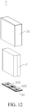
FIG. 12 is a schematic structural diagram illustrating the battery illustrated inFIG. 2 after rotating 180 degrees. -
FIG. 13 is a schematic structural diagram illustrating a tab and an adaptor piece welded with the tab in an implementation of the disclosure. -
FIG. 14 is a schematic flow chart illustrating a winding method in an implementation of the disclosure. - Reference signs of the accompanying drawings:
battery 3;cell assembly 2;cell 1;housing 31;cover 32;electrode 10;tab 11;tab root 110;first tab 13;second tab 12; length direction L; width direction W; thickness direction T;U-shaped notch 130;first end 131;internal side wall 1301;first fillet 1303;serrated notch 135;wave notch 132;square wave notch 133;bevel notch 134;adaptor piece 320;welding zone 3201. - The following will illustrate clearly and completely technical solutions of implementations of the disclosure with reference to accompanying drawings of implementations of the disclosure. Apparently, implementations described herein are merely some implementations, rather than all implementations, of the disclosure. Based on the implementations of the disclosure, all other implementations obtained by those of ordinary skill in the art without creative effort shall fall within a protection scope of the disclosure.
- Unless otherwise defined, all technical and scientific terms used herein have the same meaning as commonly understood by those skilled in the art of the present disclosure. The terms used herein in the disclosure are for the purpose of describing implementations only and are not intended to limit the disclosure.
- The terms "first", "second", and the like used in the specification, the claims, and the accompany drawings of the disclosure are used to distinguish different objects rather than describe a particular order. The words "one", "a", "the", and similar words used in the disclosure do not indicate a numerical limitation but are only used to indicate existence of at least one. The words "includes", "contains", and similar words are intended to mean that an element or object preceding the word covers an element, object, or the equivalent appearing after the word, without excluding other elements or objects. The words "connected", "coupled", or similar words are not limited to physical or mechanical connections and may include electrical connections, whether direct or indirect.
- The reference terms "an implementation", "a specific implementation", "an embodiment", or the like described herein mean that a particular feature, structure, material, or characteristic described in conjunction with the implementations or embodiments may be contained in at least one implementation or embodiment of the disclosure. The exemplary expressions of the above terms appearing in the specification does not necessarily refer to the same implementation or embodiment. Furthermore, the particular feature, structure, material, or characteristic described may be properly combined in any one or more implementations or embodiments.
- An energy-storage device in the disclosure may be a battery, or may also be battery modules including batteries, a battery pack, a battery cluster, or other devices with an electricity-energy storage function. For example, a
battery 3 illustrated inFIG. 1 will be described as follows. - As illustrated in
FIG. 2 , thebattery 3 includes acell 1, ahousing 31, and acover 32. Thecell 1 is formed by winding anelectrode 10 illustrated inFIG. 3 and a separator stacked with theelectrode 10. As illustrated inFIG. 3 , theelectrode 10 is connected with atab 11 at an end of theelectrode 10 in a width direction W of theelectrode 10, where thetab 11 includes afirst tab 13 and asecond tab 12. Thefirst tab 13 is positioned adjacent to an end of theelectrode 10 in a length direction L of theelectrode 10. As illustrated inFIG. 4 , thefirst tab 13 defines aU-shaped notch 130. - It can be understood that, the end of the
electrode 10 in the length direction L of theelectrode 10 is denoted as a winding end position of theelectrode 10 during winding. The winding end position of theelectrode 10 can be determined through theU-shaped notch 130 of thefirst tab 13 during winding to execute corresponding control operations, thereby realizing winding automation. - For convenience of subsequent depiction, the width direction W and the length direction L are defined. As illustrated in
FIG. 3 , theelectrode 10 is in a long strip shape and has a length excessively longer than a width of theelectrode 10. The width direction W is a width direction of theelectrode 10, and the length direction L is a length direction of theelectrode 10. - It can be understood that, the
first tab 13 being positioned adjacent to the end of theelectrode 10 in the length direction L of theelectrode 10 means that a distance between thefirst tab 13 and the end of theelectrode 10 in the length direction L of theelectrode 10 is shorter than a preset distance. When theU-shaped notch 130 of thefirst tab 13 is recognized, a corresponding control instruction may be generated, and theelectrode 10 is cut in response to the control instruction, to obtain thecell 1. Thus it is unnecessary to determine manually the winding end position, thereby realizing winding automation. - In an implementation, as illustrated
FIG. 4 , thefirst tab 13 has afirst end 131 away from theelectrode 10, and theU-shaped notch 130 extends from thefirst end 131 toward theelectrode 10 by cutting. TheU-shaped notch 130 has a width extending in the length direction L of theelectrode 10 and a depth extending in the width direction W of theelectrode 10, where a ratio of the width to the depth of theU-shaped notch 130 is greater than 1.5 and less than 2. - It is easier for the
U-shaped notch 130 to extend in a direction of the depth of theU-shaped notch 130 than in a direction of the width of theU-shaped notch 130, and therefore the ratio of the width to the depth of theU-shaped notch 130 is limited to be greater than 1.5 and less than 2 in the disclosure. Thus it is convenient to define theU-shaped notch 130 on thefirst tab 13, and it is possible to avoid an excessively great depth of theU-shaped notch 130 that causes insufficient spaces on thefirst tab 13 to be cut. - In an implementation, in the width direction W of the
electrode 10, thefirst tab 13 has a width less than a width of thesecond tab 12, a ratio of the width of thefirst tab 13 to the width of thesecond tab 12 is greater than 0.5 and less than 1, and a difference between the width of thefirst tab 13 and the width of thesecond tab 12 is greater than or equal to 2 mm. - According to the above arrangement, overall identification of the
first tab 13 is further improved, and recognition readiness of a recognition apparatus for thefirst tab 13 is further improved during winding of theelectrode 10. Thus it is possible to further improve a qualification rate of thecell 1 that is formed by winding theelectrode 10, thereby greatly improving production benefits. - In an implementation, the
first tab 13 has afirst fillet 1303 connected between aninternal side wall 1301 of theU-shaped notch 130 and thefirst end 131. A ratio of a radius of thefirst fillet 1303 to the width of theU-shaped notch 130 is greater than 0.15 and less than 0.2, and a ratio of the radius of thefirst fillet 1303 to the depth of theU-shaped notch 130 is greater than 0.05 and less than 0.15. - According to arrangement of the
first fillet 1303, theU-shaped notch 130 is more convenient to be processed and is not prone to burrs. Theelectrode 10 is wound to form thecell 1, and a possibility of falling metal particles from thefirst tab 13 is greatly reduced. Thus it is possible to prevent metal particles from falling into thecell 1 to cause a short circuit, and prevent burrs from piercing an encapsulation film of the battery to cause liquid leakage. -
FIG. 5 illustrates a schematic structural diagram illustrating a first tab in a second implementation of the disclosure. In the second implementation, theU-shaped notch 130 of thefirst tab 13 is omitted, in the width direction W of theelectrode 10, thefirst tab 13 has a width less than a width of thesecond tab 12, a ratio of the width of thefirst tab 13 to the width of thesecond tab 12 is greater than 0.5 and less than 1, and a difference between the width of thefirst tab 13 and the width of thesecond tab 12 is greater than or equal to 2 mm. As such, processing of thefirst tab 13 can be further simplified. Since the width of thefirst tab 13 is less than the width of thesecond tab 12, the ratio of the width of thefirst tab 13 to the width of thesecond tab 12 is greater than 0.5 and less than 1, and the difference between the width of thefirst tab 13 and the width of thesecond tab 12 is greater than or equal to 2 mm, thefirst tab 13 still has certain identification accuracy, and production of thefirst tab 13 can be simplified. - It can be understood that, in other implementations, the width of the
first tab 13 being less than the width of thesecond tab 12, the ratio of the width of thefirst tab 13 to the width of thesecond tab 12 being greater than 0.5 and less than 1, and the difference between the width of thefirst tab 13 and the width of thesecond tab 12 being greater than or equal to 2 mm can be omitted, only theU-shaped notch 130 of thefirst tab 13 is retained, but thefirst tab 13 still has certain identification accuracy. - As for specifically practical implementation processes, a type of the
first tab 13 may be chosen according to actual production needs. -
FIG. 6 illustrates a schematic structural diagram illustrating a first tab in a third implementation of the disclosure. Unlike theU-shaped notch 130 in the first implementation, thefirst tab 13 defines aserrated notch 135 in the third implementation. It can be understood that, theserrated notch 135 has strong identification to enable thefirst tab 13 to be clearly distinguished from thesecond tab 12, thereby greatly improving identification accuracy. -
FIG. 7 illustrates a schematic structural diagram illustrating a first tab in a fourth implementation of the disclosure. Unlike theU-shaped notch 130 in the first implementation, thefirst tab 13 defines awave notch 132 in the fourth implementation. It can be understood that, thewave notch 132 also has strong identification to enable thefirst tab 13 to be clearly distinguished from thesecond tab 12, and thewave notch 132 is easy and simple to be processed. Thus it is possible to improve identification accuracy and is convenient to process thefirst tab 13 through thewave notch 132. -
FIG. 8 illustrates a schematic structural diagram illustrating a first tab in a fifth implementation of the disclosure. Unlike theU-shaped notch 130 in the first implementation, thefirst tab 13 defines asquare wave notch 133 in the fifth implementation. It can be understood that thesquare wave notch 133 also has strong identification to enable thefirst tab 13 to be clearly distinguished from thesecond tab 12, and thesquare wave notch 133 is easy and simple to be processed. Thus it is possible to improve identification accuracy and is convenient to process thefirst tab 13 through thesquare wave notch 133. -
FIG. 9 illustrates a schematic structural diagram illustrating a first tab in a sixth implementation of the disclosure. Unlike theU-shaped notch 130 in the first implementation, in the fifth implementation, thefirst tab 13 defines abevel notch 134 at an end. It can be understood that thebevel notch 134 also has strong identification to enable thefirst tab 13 to be clearly distinguished from thesecond tab 12, and thebevel notch 134 is easy and simple to be processed. Thus it is possible to improve identification accuracy and is convenient to process thefirst tab 13 through thebevel notch 134. - It can be understood that, unlike the
U-shaped notch 130 in the first implementation, thefirst tab 13 may also define a semi-circular notch, or the like, in other implementations. - It can be understood that, unlike the
U-shaped notch 130 in the first implementation, thefirst tab 13 may also define one of an injection-molded serrated notch, a wave notch, a square wave notch, or a semi-circular notch or a combination thereof, in other implementations. - It can be understood that, unlike the
U-shaped notch 130 in the first implementation, thefirst tab 13 is provided with an indentation with identification information in other implementations, where the identification information may be, but is not limited to, one of a square pattern, an oval pattern, a heart-shaped pattern, a trapezoidal pattern, or a specific pattern or a combination thereof. - The
first tab 13 is provided with the indentation with the identification information, so that no metal particle falls and no burr is generated during processing of thefirst tab 13. Thus it is possible to avoid lots of secondary hazards and greatly improve a safety factor. Furthermore, the indentation on thefirst tab 13 enables that an apparatus is able to determine automatically a winding end position, thereby realizing winding automation. - It can be understood that, unlike the
U-shaped notch 130 in the first implementation, thefirst tab 13 is provided with an adhesive member with identification information in other implementations, where the identification information may be, but is not limited to, one of a square pattern, an oval pattern, a heart-shaped pattern, a trapezoidal pattern, or a specific pattern or a combination thereof, or one of a specific number, a word, or the like or a combination thereof. - When striking adhesive members are used, identification of the
first tab 13 can be greatly improved, and it is unnecessary to process thefirst tab 13 to make thefirst tab 13 have a cut. Thefirst tab 13 has a stronger structural strength, and thus no breakage occurs in subsequent operations of tab welding. As such, the adhesive member can protect thefirst tab 13 from secondary hazards, and can also be functioned as the winding end position, thereby realizing winding automation. - It can be understood that, unlike the
U-shaped notch 130 in the first implementation, thefirst tab 13 is provided with a coating pattern or printing pattern with identification information in other implementations, where the identification information may be, but is not limited to, one of a square pattern, an oval pattern, a heart-shaped pattern, a trapezoidal pattern, or a specific pattern or a combination thereof, or one of a specific number, a word, or the like or a combination thereof. - When striking coating patterns or printing patterns are used, identification of the
first tab 13 can be greatly improved, and it is unnecessary to process thefirst tab 13 to make thefirst tab 13 have a cut. Thefirst tab 13 has a stronger structural strength, and thus no breakage occurs in subsequent operations of tab welding. As such, the coating pattern or printing pattern can protect thefirst tab 13 from secondary hazards, and can also be functioned as the winding end position, thereby realizing winding automation. - It can be understood that, unlike the
U-shaped notch 130 in the first implementation, thefirst tab 13 defines at least one identification hole arranged at intervals in other implementations. In the implementation, the identification hole is in a circular shape. It can be understood that, in other implementations, the identification hole is in a shape of one or more of square, oval, heart, trapezoid, or a hollow pattern. In an implementation, the identification hole needs to be spaced at a preset distance from a welding zone of thetab 11, thereby preventing thefirst tab 13 from being broken during welding due to the U-shaped notch defined on thefirst tab 13. In an implementation, the preset distance is greater than 0.5 mm. - A winding end position of the
cell 1 can be identified as the identification hole. Thus it is unnecessary to determine manually the winding end position, thereby realizing winding automation. - It can be understood that, in some optional implementations, a feature on the
first tab 13 functioning in identification includes, but is not limited to, one of: one of theU-shaped notch 130, theserrated notch 135, thewave notch 132, thesquare wave notch 133, or thebevel notch 134 or a combination thereof, the indentation with the identification information, the adhesive member with the identification information, the coating pattern or printing pattern with the identification information, the identification hole, or the width of thefirst tab 13 being less than the width of thesecond tab 12 in the width direction W of theelectrode 10 or a combination thereof. -
FIG. 10 illustrates a schematic isometric view of a cell in an implementation of the disclosure. Theelectrode 10 and the separator are wound to form thecell 1, thetab 11 is disposed through stacking, and thefirst tab 13 is located at one side of thetab 11 away from a center of thetab 11 in a thickness direction T of thecell 1. As illustrated inFIG. 10 , the thickness direction T of thecell 1 refers to a thickness direction T of a roll core formed by winding theelectrode 10, and the width direction W and the length direction L mentioned above each are perpendicular to the thickness direction T. - In the disclosure, the
first tab 13 is an outermost tab and located at one side of the tab away from the center of the tab in the thickness direction T of thecell 1. When theU-shaped notch 130 is recognized, winding ends. -
FIG. 11 illustrates a schematic structural diagram illustrating a cell assembly in an implementation of the disclosure. Acell assembly 2 includes at least twocells 1 that are stacked, where the at least twocells 1 are coupled in series or in parallel. - Coupling of the at least two
cells 1 in series or in parallel can increase a capacitance. - As illustrated in
FIG. 2 ,FIG. 12 , andFIG. 13 , thebattery 3 includes acell assembly 2, ahousing 31, and acover 32, where thecell assembly 2 is received in thehousing 31, and thecover 32 is provided with anadaptor piece 320. As illustrated inFIG. 13 , thetab 11 is welded with theadaptor piece 320 at awelding zone 3201, and a distance between theU-shaped notch 130 and thewelding zone 3201 is greater than 0.5 mm. - Since welding of the
tab 11 is ultrasonic welding with great impact, arrangement of theU-shaped notch 130 is required to avoid thewelding zone 3201 on thetab 11, i.e., a distance therebetween is greater than 0.5 mm, thereby preventing thefirst tab 13 from being broken during welding due to theU-shaped notch 130 defined on thefirst tab 13. - In an implementation, as illustrated in
FIG. 13 again, thetab 11 has atab root 110 at one side of thetab 11 close to theelectrode 10, where a distance between thewelding zone 3201 and one side of theadaptor piece 320 close to thetab root 110 is greater than or equal to 2 mm, and a distance between thewelding zone 3201 and one side of theadaptor piece 320 away from thetab root 110 is greater than or equal to 10 mm. It can be understood that, the schematic diagram ofFIG. 13 is not a schematic diagram of a final form of thebattery 3 but is a schematic diagram illustrating a distance relation between thewelding zone 3201 and theadaptor piece 320. In actual products, theelectrode 10 is wound to form the roll core,multiple tabs 11 are stacked and bent from thetab root 110 to be approximately parallel to an end surface of the roll core, and theadaptor piece 320 attached to themultiple tabs 11 is welded with themultiple tabs 11. - A distance D1 between the
welding zone 3201 and one side of theadaptor piece 320 close to thetab root 110 is greater than or equal to 2 mm, and a distance D2 between thewelding zone 3201 and one side of theadaptor piece 320 away from thetab root 110 is greater than or equal to 10 mm. As such, thewelding zone 3201 is defined at a relatively central position of theadaptor piece 320 and may not be defined at an edge of theadaptor piece 320. Thus it is possible to avoid poor contact caused by breaking theadaptor piece 320 due to vibration of ultrasonic welding, thereby improving reliability and safety of connection. - In an implementation, the
adaptor piece 320 is approximately flush with thetab root 110 at an end of theadaptor piece 320 close to thetab root 110 in the width direction W, and a distance that theadaptor piece 320 extends beyond an end of thesecond tab 12 away from thetab root 110 in the width direction W is greater than or equal to 2 mm. - Projections of the
tab 11 and thefirst tab 13 on a surface of theadaptor piece 320 completely fall on theadaptor piece 320, so that theadaptor piece 320 has sufficient contact areas with thetab 11, thereby further improving reliability of connection between theadaptor piece 320 and thetab 11 and thefirst tab 13. - In an implementation, the
battery 3 is one of a lithium iron phosphate battery, a ternary lithium battery, a lithium battery, or the like. - In an implementation, the
housing 31 is one of an aluminum housing, a steel housing, a stainless steel housing, or the like. - In an implementation, the
battery 3 is a square-housing battery. - An electrical apparatus is further provided in the disclosure. The electrical apparatus includes at least one energy-storage device, where the energy-storage device is configured to power the electrical apparatus.
- Refer to
FIG. 14 , which is a schematic flow chart illustrating a winding method in an implementation of the disclosure. The winding method is for manufacturing the energy-storage device mentioned above and includes the following. - At
step 141, theelectrode 10 and the separator stacked with theelectrode 10 are placed in a winding machine, and theelectrode 10 and the separator are wound by the winding machine. - At
step 142, a sensor of the winding machine senses theU-shaped notch 130 of thefirst tab 13 and a position of thefirst tab 13 is determined. - At
step 143, theelectrode 10 is cut at a position close to thefirst tab 13 in the length direction L of theelectrode 10 to end winding. - In the disclosure, the
first tab 13 defines theU-shaped notch 130. A winding end position of thecell 1 is marked as theU-shaped notch 130, and the winding end position is determined according to theU-shaped notch 130 in a process that theelectrode 10 is wound to form thecell 1. The winding end position of thecell 1 is recognized by recognizing theU-shaped notch 130, and theelectrode 10 is cut at the position close to thefirst tab 13 to end winding. Thus it is unnecessary to determine manually the winding end position, thereby realizing winding automation. - In the foregoing implementations, description of each implementation has its own emphasis. For the parts not described in detail in one implementation, reference may be made to related descriptions in other implementations.
- It can be understood that, in one or more implementations provided in the disclosure, the implementations of the energy-storage device disclosed are merely illustrative and may also have other implementation forms.
- The above are implementation manners of implementations of the disclosure, it should be noted that for those of ordinary skill in the art, without departing from the principles of implementations of the disclosure, various improvements and embellishments can also be made, where the improvements and embellishments are also considered in the scope of protection of the disclosure.
Claims (11)
- An energy-storage device, comprising an electrode (10) and a separator, wherein the electrode (10) and the separator are stacked and wound to form a cell (1), the electrode (10) is connected with a tab (11) at an end of the electrode (10) in a width direction (W) of the electrode (10), wherein the tab (11) comprises a first tab (13) and a second tab (12), and wherein the first tab (13) is positioned adjacent to an end of the electrode (10) in a length direction (L) of the electrode (10), and the first tab (13) defines a U-shaped notch (130).
- The energy-storage device of claim 1, wherein the first tab (13) has a first end (131) away from the electrode (10), and the U-shaped notch (130) extends from the first end (131) toward the electrode (10) by cutting, and has a width extending in the length direction (L) of the electrode (10) and a depth extending in the width direction (W) of the electrode (10), and wherein a ratio of the width to the depth of the U-shaped notch (130) is equal to or greater than 1.5 and less than 2.
- The energy-storage device of claim 1 or 2, wherein in the width direction (W) of the electrode (10), the first tab (13) has a width less than a width of the second tab, a ratio of the width of the first tab (13) to the width of the second tab is greater than 0.5 and less than 1, and a difference between the width of the first tab (13) and the width of the second tab is greater than or equal to 2 mm.
- The energy-storage device of any one of claims 1 to 3, wherein the first tab (13) is provided with at least one of an indentation with identification information, an adhesive member with identification information, a coating pattern with identification information, or a printing pattern with identification information.
- The energy-storage device of any one of claims 1 to 4, wherein the first tab (13) has a first fillet (1303) connected between an internal side wall (1301) of the U-shaped notch (130) and the first end (131).
- The energy-storage device of claim 5, wherein a ratio of a radius of the first fillet (1303) to the width of the U-shaped notch (130) is greater than 0.15 and less than 0.2, and a ratio of the radius of the first fillet (1303) to the depth of the U-shaped notch (130) is greater than 0.05 and less than 0.15.
- The energy-storage device of any one of claims 1 to 6, wherein the electrode (10) and the separator are wound to form the cell (1), the tab (11) is disposed through stacking, and the first tab (13) is located at one side of the tab (11) away from a center of the tab (11) in a thickness direction (T) of the cell (1).
- The energy-storage device of any one of claims 1 to 7, further comprising a housing (31) and a cover (32), wherein the cell (1) is received in the housing (31), the cover (32) is provided with an adaptor piece (320), the tab (11) is stacked and welded with the adaptor piece (320) at a welding zone (3201), and wherein on the first tab (13), a distance between the U-shaped notch (130) and the welding zone (3201) is greater than 0.5 mm.
- The energy-storage device of claim 8, wherein the tab (11) has a tab root (110) at one side of the tab (11) close to the electrode (10), and wherein a distance (D1) between the welding zone (3201) and one side of the adaptor piece (320) close to the tab root (110) is greater than or equal to 2 mm, a distance (D2) between the welding zone (3201) and one side of the adaptor piece (320) away from the tab root (110) is greater than or equal to 10 mm, and a distance that the adaptor piece (320) extends beyond an end of the second tab (12) away from the tab root (110) in the width direction (W) is greater than or equal to 2 mm.
- An electrical apparatus, comprising at least one energy-storage device of any one of claims 1 to 9, the energy-storage device being configured to power the electrical apparatus.
- A winding method for manufacturing the energy-storage device of any one of claims 1 to 9 and comprising:at step 1, placing the electrode (10) and the separator stacked with the electrode (10) in a winding machine, and winding, by the winding machine, the electrode (10) and the separator;at step 2, sensing, by a sensor of the winding machine, the U-shaped notch (130) of the first tab (13), and determining a position of the first tab (13); andat step 3, cutting the electrode (10) at a position close to the first tab (13) in the length direction (L) of the electrode (10) to end winding.
Applications Claiming Priority (1)
| Application Number | Priority Date | Filing Date | Title |
|---|---|---|---|
| PCT/CN2022/131549 WO2024098425A1 (en) | 2022-11-11 | 2022-11-11 | Energy storage apparatus, electric device, and winding method |
Publications (2)
| Publication Number | Publication Date |
|---|---|
| EP4583232A1 true EP4583232A1 (en) | 2025-07-09 |
| EP4583232A4 EP4583232A4 (en) | 2026-01-21 |
Family
ID=91031804
Family Applications (1)
| Application Number | Title | Priority Date | Filing Date |
|---|---|---|---|
| EP22964893.6A Pending EP4583232A4 (en) | 2022-11-11 | 2022-11-11 | ENERGY STORAGE DEVICE, ELECTRICAL DEVICE AND WINDING METHOD |
Country Status (2)
| Country | Link |
|---|---|
| EP (1) | EP4583232A4 (en) |
| WO (1) | WO2024098425A1 (en) |
Family Cites Families (9)
| Publication number | Priority date | Publication date | Assignee | Title |
|---|---|---|---|---|
| JP2005122940A (en) * | 2003-10-14 | 2005-05-12 | Matsushita Electric Ind Co Ltd | Battery and manufacturing method thereof |
| CN102916226B (en) * | 2012-09-20 | 2016-06-22 | 东莞新能源科技有限公司 | The method for winding of square power lithium ion battery |
| JP6357776B2 (en) * | 2014-01-06 | 2018-07-18 | 株式会社ジェイテクト | Method for manufacturing power storage device |
| KR102106109B1 (en) * | 2016-01-25 | 2020-04-29 | 주식회사 엘지화학 | Lithium secondary battery |
| EP3902046A4 (en) * | 2018-12-19 | 2022-03-02 | SANYO Electric Co., Ltd. | SECONDARY BATTERY AND ITS MANUFACTURING METHOD |
| US20230223658A1 (en) * | 2020-06-19 | 2023-07-13 | Varta Microbattery Gmbh | Lithium-ion cell with a high specific energy density |
| CA3202317A1 (en) * | 2021-01-19 | 2022-07-28 | Lg Energy Solution, Ltd. | Battery and current collector applied thereto, and battery pack and vehicle including the same |
| CN216450703U (en) * | 2021-10-19 | 2022-05-06 | 厦门海辰新能源科技有限公司 | Secondary battery's electric core and secondary battery |
| CN217134453U (en) * | 2022-04-21 | 2022-08-05 | 合肥国轩高科动力能源有限公司 | Single-diaphragm laminated cell unit and laminated cell structure |
-
2022
- 2022-11-11 WO PCT/CN2022/131549 patent/WO2024098425A1/en not_active Ceased
- 2022-11-11 EP EP22964893.6A patent/EP4583232A4/en active Pending
Also Published As
| Publication number | Publication date |
|---|---|
| WO2024098425A1 (en) | 2024-05-16 |
| EP4583232A4 (en) | 2026-01-21 |
Similar Documents
| Publication | Publication Date | Title |
|---|---|---|
| EP3051610B1 (en) | Electrode assembly and rechargeable battery having electrode tab | |
| US11450932B2 (en) | Battery, preparation method thereof and electric device | |
| US20240088527A1 (en) | Battery and portable electrical device | |
| EP4333099A1 (en) | Battery electrode plate, battery, and method for manufacturing battery electrode plate | |
| JP2014022116A (en) | Electrode plate for secondary battery, and method for manufacturing electrode plate for secondary battery | |
| US12191530B2 (en) | Energy-storage device, electrical apparatus, and winding method | |
| CN115458879A (en) | Battery cell and battery cell manufacturing method | |
| US20240222817A1 (en) | Battery, manufacturing method thereof and electronic product | |
| JP4438784B2 (en) | Power storage device | |
| US9059460B2 (en) | Prismatic secondary battery | |
| KR102368090B1 (en) | Electrode assembly and rechargeable battery having electrode ta1p | |
| EP4679513A1 (en) | Secondary battery, battery assembly and electronic device | |
| EP3226338A1 (en) | Wound-type cell | |
| EP4203151A1 (en) | Apparatus and method for checking for mis-assembly of battery cell activation tray or twisting thereof during operation | |
| CN115425365A (en) | Current collecting assembly, battery pack and electric equipment | |
| CN207441856U (en) | Pole piece and electrode assembly | |
| EP4583232A1 (en) | Energy storage apparatus, electric device, and winding method | |
| CN218385635U (en) | Electrode plate, battery cell and button cell | |
| JP2019029189A (en) | Square secondary battery and battery pack using the same | |
| CN208570816U (en) | Convenient for the column lithium ion end face weld battery of fluid injection | |
| JP2003272598A (en) | Non-aqueous electrolyte battery and method of manufacturing the same | |
| CN114976512A (en) | Pole piece, electric core structure, lithium battery and electronic equipment | |
| CN217903145U (en) | Pole piece and battery | |
| CN218385268U (en) | Electrode plate, battery cell and button cell | |
| CN224005883U (en) | A type of all-tab electrode and cylindrical lithium-ion battery |
Legal Events
| Date | Code | Title | Description |
|---|---|---|---|
| STAA | Information on the status of an ep patent application or granted ep patent |
Free format text: STATUS: THE INTERNATIONAL PUBLICATION HAS BEEN MADE |
|
| PUAI | Public reference made under article 153(3) epc to a published international application that has entered the european phase |
Free format text: ORIGINAL CODE: 0009012 |
|
| STAA | Information on the status of an ep patent application or granted ep patent |
Free format text: STATUS: REQUEST FOR EXAMINATION WAS MADE |
|
| 17P | Request for examination filed |
Effective date: 20250401 |
|
| AK | Designated contracting states |
Kind code of ref document: A1 Designated state(s): AL AT BE BG CH CY CZ DE DK EE ES FI FR GB GR HR HU IE IS IT LI LT LU LV MC ME MK MT NL NO PL PT RO RS SE SI SK SM TR |
|
| A4 | Supplementary search report drawn up and despatched |
Effective date: 20251219 |
|
| RIC1 | Information provided on ipc code assigned before grant |
Ipc: H01M 10/0583 20100101AFI20251215BHEP Ipc: H01M 10/052 20100101ALI20251215BHEP Ipc: H01M 50/538 20210101ALI20251215BHEP Ipc: H01M 50/533 20210101ALI20251215BHEP Ipc: H01M 10/04 20060101ALI20251215BHEP Ipc: H01M 10/0587 20100101ALI20251215BHEP Ipc: H01M 50/15 20210101ALI20251215BHEP Ipc: H01M 50/528 20210101ALI20251215BHEP Ipc: H01M 10/0525 20100101ALI20251215BHEP Ipc: H01M 50/536 20210101ALI20251215BHEP |
|
| DAV | Request for validation of the european patent (deleted) | ||
| DAX | Request for extension of the european patent (deleted) |