EP3051610B1 - Electrode assembly and rechargeable battery having electrode tab - Google Patents
Electrode assembly and rechargeable battery having electrode tab Download PDFInfo
- Publication number
- EP3051610B1 EP3051610B1 EP16150338.8A EP16150338A EP3051610B1 EP 3051610 B1 EP3051610 B1 EP 3051610B1 EP 16150338 A EP16150338 A EP 16150338A EP 3051610 B1 EP3051610 B1 EP 3051610B1
- Authority
- EP
- European Patent Office
- Prior art keywords
- electrode
- tabs
- tab
- assembly
- distances
- Prior art date
- Legal status (The legal status is an assumption and is not a legal conclusion. Google has not performed a legal analysis and makes no representation as to the accuracy of the status listed.)
- Active
Links
- 239000011149 active material Substances 0.000 claims description 7
- 229910009447 Y1-Yn Inorganic materials 0.000 claims 2
- 229910009449 Y1-Yn-1 Inorganic materials 0.000 claims 2
- 238000004804 winding Methods 0.000 description 23
- 229910008355 Si-Sn Inorganic materials 0.000 description 5
- 229910006453 Si—Sn Inorganic materials 0.000 description 5
- 238000003466 welding Methods 0.000 description 5
- 230000008878 coupling Effects 0.000 description 4
- 238000010168 coupling process Methods 0.000 description 4
- 238000005859 coupling reaction Methods 0.000 description 4
- 238000009413 insulation Methods 0.000 description 4
- 239000007773 negative electrode material Substances 0.000 description 4
- 239000007774 positive electrode material Substances 0.000 description 4
- 229910052751 metal Inorganic materials 0.000 description 3
- 239000002184 metal Substances 0.000 description 3
- 238000007789 sealing Methods 0.000 description 3
- WHXSMMKQMYFTQS-UHFFFAOYSA-N Lithium Chemical compound [Li] WHXSMMKQMYFTQS-UHFFFAOYSA-N 0.000 description 2
- 229910052782 aluminium Inorganic materials 0.000 description 2
- XAGFODPZIPBFFR-UHFFFAOYSA-N aluminium Chemical compound [Al] XAGFODPZIPBFFR-UHFFFAOYSA-N 0.000 description 2
- 238000005516 engineering process Methods 0.000 description 2
- 229910052744 lithium Inorganic materials 0.000 description 2
- 238000004519 manufacturing process Methods 0.000 description 2
- 238000000034 method Methods 0.000 description 2
- RYGMFSIKBFXOCR-UHFFFAOYSA-N Copper Chemical compound [Cu] RYGMFSIKBFXOCR-UHFFFAOYSA-N 0.000 description 1
- HBBGRARXTFLTSG-UHFFFAOYSA-N Lithium ion Chemical compound [Li+] HBBGRARXTFLTSG-UHFFFAOYSA-N 0.000 description 1
- 230000002159 abnormal effect Effects 0.000 description 1
- 239000002388 carbon-based active material Substances 0.000 description 1
- 238000006243 chemical reaction Methods 0.000 description 1
- 229910052802 copper Inorganic materials 0.000 description 1
- 239000010949 copper Substances 0.000 description 1
- 238000007599 discharging Methods 0.000 description 1
- 239000003792 electrolyte Substances 0.000 description 1
- 230000002349 favourable effect Effects 0.000 description 1
- 229910001416 lithium ion Inorganic materials 0.000 description 1
- 238000012986 modification Methods 0.000 description 1
- 230000004048 modification Effects 0.000 description 1
- 239000011255 nonaqueous electrolyte Substances 0.000 description 1
- 229920000642 polymer Polymers 0.000 description 1
- 229920005672 polyolefin resin Polymers 0.000 description 1
- 229910001220 stainless steel Inorganic materials 0.000 description 1
- 239000010935 stainless steel Substances 0.000 description 1
- 239000010409 thin film Substances 0.000 description 1
- 229910052718 tin Inorganic materials 0.000 description 1
Images


Classifications
-
- H—ELECTRICITY
- H01—ELECTRIC ELEMENTS
- H01M—PROCESSES OR MEANS, e.g. BATTERIES, FOR THE DIRECT CONVERSION OF CHEMICAL ENERGY INTO ELECTRICAL ENERGY
- H01M10/00—Secondary cells; Manufacture thereof
- H01M10/04—Construction or manufacture in general
- H01M10/0404—Machines for assembling batteries
- H01M10/0409—Machines for assembling batteries for cells with wound electrodes
-
- H—ELECTRICITY
- H01—ELECTRIC ELEMENTS
- H01M—PROCESSES OR MEANS, e.g. BATTERIES, FOR THE DIRECT CONVERSION OF CHEMICAL ENERGY INTO ELECTRICAL ENERGY
- H01M4/00—Electrodes
- H01M4/02—Electrodes composed of, or comprising, active material
- H01M4/13—Electrodes for accumulators with non-aqueous electrolyte, e.g. for lithium-accumulators; Processes of manufacture thereof
-
- H—ELECTRICITY
- H01—ELECTRIC ELEMENTS
- H01M—PROCESSES OR MEANS, e.g. BATTERIES, FOR THE DIRECT CONVERSION OF CHEMICAL ENERGY INTO ELECTRICAL ENERGY
- H01M10/00—Secondary cells; Manufacture thereof
- H01M10/04—Construction or manufacture in general
- H01M10/0431—Cells with wound or folded electrodes
-
- H—ELECTRICITY
- H01—ELECTRIC ELEMENTS
- H01M—PROCESSES OR MEANS, e.g. BATTERIES, FOR THE DIRECT CONVERSION OF CHEMICAL ENERGY INTO ELECTRICAL ENERGY
- H01M10/00—Secondary cells; Manufacture thereof
- H01M10/05—Accumulators with non-aqueous electrolyte
- H01M10/052—Li-accumulators
-
- H—ELECTRICITY
- H01—ELECTRIC ELEMENTS
- H01M—PROCESSES OR MEANS, e.g. BATTERIES, FOR THE DIRECT CONVERSION OF CHEMICAL ENERGY INTO ELECTRICAL ENERGY
- H01M10/00—Secondary cells; Manufacture thereof
- H01M10/05—Accumulators with non-aqueous electrolyte
- H01M10/058—Construction or manufacture
- H01M10/0587—Construction or manufacture of accumulators having only wound construction elements, i.e. wound positive electrodes, wound negative electrodes and wound separators
-
- H—ELECTRICITY
- H01—ELECTRIC ELEMENTS
- H01M—PROCESSES OR MEANS, e.g. BATTERIES, FOR THE DIRECT CONVERSION OF CHEMICAL ENERGY INTO ELECTRICAL ENERGY
- H01M4/00—Electrodes
- H01M4/02—Electrodes composed of, or comprising, active material
- H01M4/64—Carriers or collectors
- H01M4/70—Carriers or collectors characterised by shape or form
-
- H—ELECTRICITY
- H01—ELECTRIC ELEMENTS
- H01M—PROCESSES OR MEANS, e.g. BATTERIES, FOR THE DIRECT CONVERSION OF CHEMICAL ENERGY INTO ELECTRICAL ENERGY
- H01M50/00—Constructional details or processes of manufacture of the non-active parts of electrochemical cells other than fuel cells, e.g. hybrid cells
- H01M50/10—Primary casings, jackets or wrappings of a single cell or a single battery
- H01M50/147—Lids or covers
-
- H—ELECTRICITY
- H01—ELECTRIC ELEMENTS
- H01M—PROCESSES OR MEANS, e.g. BATTERIES, FOR THE DIRECT CONVERSION OF CHEMICAL ENERGY INTO ELECTRICAL ENERGY
- H01M50/00—Constructional details or processes of manufacture of the non-active parts of electrochemical cells other than fuel cells, e.g. hybrid cells
- H01M50/50—Current conducting connections for cells or batteries
- H01M50/531—Electrode connections inside a battery casing
- H01M50/538—Connection of several leads or tabs of wound or folded electrode stacks
-
- H—ELECTRICITY
- H01—ELECTRIC ELEMENTS
- H01M—PROCESSES OR MEANS, e.g. BATTERIES, FOR THE DIRECT CONVERSION OF CHEMICAL ENERGY INTO ELECTRICAL ENERGY
- H01M10/00—Secondary cells; Manufacture thereof
- H01M10/04—Construction or manufacture in general
- H01M10/0413—Large-sized flat cells or batteries for motive or stationary systems with plate-like electrodes
-
- H—ELECTRICITY
- H01—ELECTRIC ELEMENTS
- H01M—PROCESSES OR MEANS, e.g. BATTERIES, FOR THE DIRECT CONVERSION OF CHEMICAL ENERGY INTO ELECTRICAL ENERGY
- H01M2220/00—Batteries for particular applications
- H01M2220/20—Batteries in motive systems, e.g. vehicle, ship, plane
-
- Y—GENERAL TAGGING OF NEW TECHNOLOGICAL DEVELOPMENTS; GENERAL TAGGING OF CROSS-SECTIONAL TECHNOLOGIES SPANNING OVER SEVERAL SECTIONS OF THE IPC; TECHNICAL SUBJECTS COVERED BY FORMER USPC CROSS-REFERENCE ART COLLECTIONS [XRACs] AND DIGESTS
- Y02—TECHNOLOGIES OR APPLICATIONS FOR MITIGATION OR ADAPTATION AGAINST CLIMATE CHANGE
- Y02E—REDUCTION OF GREENHOUSE GAS [GHG] EMISSIONS, RELATED TO ENERGY GENERATION, TRANSMISSION OR DISTRIBUTION
- Y02E60/00—Enabling technologies; Technologies with a potential or indirect contribution to GHG emissions mitigation
- Y02E60/10—Energy storage using batteries
-
- Y—GENERAL TAGGING OF NEW TECHNOLOGICAL DEVELOPMENTS; GENERAL TAGGING OF CROSS-SECTIONAL TECHNOLOGIES SPANNING OVER SEVERAL SECTIONS OF THE IPC; TECHNICAL SUBJECTS COVERED BY FORMER USPC CROSS-REFERENCE ART COLLECTIONS [XRACs] AND DIGESTS
- Y02—TECHNOLOGIES OR APPLICATIONS FOR MITIGATION OR ADAPTATION AGAINST CLIMATE CHANGE
- Y02P—CLIMATE CHANGE MITIGATION TECHNOLOGIES IN THE PRODUCTION OR PROCESSING OF GOODS
- Y02P70/00—Climate change mitigation technologies in the production process for final industrial or consumer products
- Y02P70/50—Manufacturing or production processes characterised by the final manufactured product
Definitions
- the described technology generally relates to an electrode assembly and a secondary battery including the electrode assembly.
- a rechargeable (or secondary) battery can be charged and discharged multiple times, unlike a primary battery.
- a low-capacity rechargeable battery is used for small portable electronic devices such as a portable phone, a smartphone, a tablet computer, a notebook computer, and a camcorder.
- a high-capacity rechargeable battery (most often used with an array of batteries or battery cells) is widely used as a power source for driving a motor for a hybrid vehicle or an electric vehicle.
- the high-output rechargeable battery is configured as a high-capacity rechargeable battery in which a plurality of rechargeable batteries are connected in series so as to be used in driving a device requiring high power, for example, a motor for an electric vehicle.
- one high-capacity rechargeable battery generally includes a plurality of rechargeable batteries which are connected in series, and the rechargeable battery may have a cylindrical or angular shape.
- the rechargeable battery has an electrode assembly implementing charging and discharging.
- the electrode assembly includes a positive electrode, a negative electrode, and a separator interposed between the positive and negative electrodes.
- the electrode assembly is often formed with a structure in which a plurality of positive electrode plates and negative electrode plates are stacked or a structure in which band-shaped positive and negative electrodes are wound.
- EP1207565 discloses a battery comprising an electricity-generating element comprising a strip-form positive electrode (11), a strip-form negative electrode (12), and a strip-form separator (13), said positive electrode and said negative electrode being spirally wound through said separator and said positive electrode and said negative electrode respectively having current collecting lugs (11a,12a) protruding from a side thereof.
- JP2011-171079 discloses an electrode assembly having the electrode tabs separated at specific distances. The present invention is defined by the features of claim 1 and relates to an electrode assembly.
- One inventive aspect relates to an electrode assembly and a secondary battery having an electrode tab.
- Another aspect is an electrode assembly capable of being easily wound, and a rechargeable battery including the same.
- the point at which the winding of the electrode assembly is ended can be easily detected using the electrode tab placed at the outermost side of the electrode assembly.
- an electrode assembly as set out in claim 1.
- Preferred features are set out in claims 2 to 6.
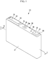
- FIG. 1 is a perspective view showing a rechargeable battery 101 according to an embodiment
- FIG. 2 is a cross-sectional view taken along line II - II in FIG. 2 .
- the rechargeable battery 101 includes an electrode assembly 10 in which a positive electrode (first electrode) 11 and a negative electrode (second electrode) 12 are wound with a separator 13 interposed therebetween, a case 27 containing the electrode assembly 10, and a cap assembly 30 connected to an opening of the case 27.
- the rechargeable battery 101 will be described by exemplifying a lithium ion rechargeable battery with an angular shape. However, embodiments of the present invention are not limited thereto, and may be applied to various types of batteries, such as a lithium polymer battery or a cylindrical shaped battery.
- the rechargeable battery 101 can be a high-output rectangular shaped battery, and may be formed as, particularly, a battery for powering a motor used to start a vehicle. Since such battery requires momentary high power, a structure in which electrode tabs protrude upward is favorable, as in the present embodiment. However, it is very difficult to accurately align electrode tabs in cases of the structure in which the electrode tabs protrude upwardly. In order to accurately align the electrode tabs, a point at which winding is started and a point at which the winding is ended need to be accurately specified, and thus the electrode tabs can be accurately stacked without missing each other.
- the case 27 can have a substantially cuboid shape, and an opening is formed in one surface thereof.
- the case 27 may be formed of a metal, such as aluminum or stainless steel.
- the cap assembly 30 includes a cap plate 31 covering the opening of the case 27, a first terminal 21 protruding outwardly from the cap plate 31 and electrically connected to the positive electrode 11, and a second terminal 22 protruding outwardly from the cap plate 31 and electrically connected to the negative electrode 12.
- the cap plate 31 can have a long plate shape that is lengthened in one direction, and is connected to the opening of the case 27.
- the cap plate 31 is equipped with a sealing stopper 38, which is installed at an electrolyte inlet 32, and a vent plate 34, which is installed at a vent hole 39 and has a notch 39a which can be opened at a predetermined pressure.
- the first and second terminals 21 and 22 are installed on the cap plate 31.
- the first terminal 21 is electrically connected to the positive electrode 11 via a first current collecting member 41, and the second terminal 22 is electrically connected to the negative electrode 12 via a second current collecting member 42.
- first terminal 21 may be electrically connected to the negative electrode and the second terminal 22 may be electrically connected to the positive electrode.
- the first terminal 21 can have a rectangular plate shape.
- the first terminal 21 is electrically connected to the positive electrode 11 via a connection terminal 25 bonded to the first current collecting member 41.
- the connection terminal 25 can have a pillar shape, and can be attached to the first terminal 21 by welding while an upper end of the connection terminal 25 is fitted into the first terminal 21.
- the upper end of the connection terminal 25 can be attached to the first current collecting member 41 by welding, and the first current collecting member 41 electrically connects the connection terminal 25 and the positive electrode 11.
- a sealing gasket 59 is inserted into a hole through which the terminal passes, between the first terminal 21 and the cap plate 31, and a lower insulation member 43 supporting the first current collecting member 41 is formed below the cap plate 31.
- connection member 58 electrically connecting the first terminal 21 and the cap plate 31 is formed below the first terminal 21. Hence, the cap plate 31 and the case 27 are positively charged.
- the second terminal 22 can have a rectangular plate shape.
- the second terminal 22 is electrically connected to the negative electrode 12 via a connection terminal 26 bonded to the second current collecting member 42.
- An upper end of the connection terminal 26 is attached to the second terminal 22 while passing through the first cap plate 31 and the second terminal 22.
- connection terminal 26 can have a pillar shape, and can be attached to the second terminal 22 while an upper end of the connection terminal 26 is fitted into the second terminal 22.
- the upper end of the connection terminal 26 can be attached to the second current collecting member 42 by welding, and the second current collecting member 42 electrically connects the connection terminal 26 and the negative electrode 12.
- a sealing gasket 55 is inserted into a hole through which the connection terminal 26 passes, between the second terminal 22 and the cap plate 31, and a lower insulation member 45 for insulating the second current collecting member 42 and the second terminal 22 from each other by the cap plate 31 is formed below the cap plate 31.
- a short circuit protrusion protruding toward a short circuit hole 37 is formed on a lower portion of the second terminal 22.
- the second terminal 22 is extended in one direction to cover the short circuit hole 37.
- An upper insulation member 54 electrically insulating the second terminal 22 and the cap plate 31 is formed between the second terminal 22 and the cap plate 31.
- the cap assembly 30 includes a short circuit member 56 for short circuiting the positive electrode 11 and the negative electrode 12, the short circuit member 56 is electrically connected to the cap plate 31, and is transformed to be connected to the second terminal 22 when the inner pressure of the rechargeable battery 101 rises.
- the cap plate 31 has the short circuit hole 37, and the short circuit member 56 is placed between the upper insulation member 54 and the cap plate 31 in the short circuit hole 37.
- the second terminal 22 is placed in the short circuit hole 37 to cover the short circuit hole 37.
- the short circuit member 56 includes a curved portion which is bent in an arc shape to be convex downward, and an edge portion formed outside the curved portion and fixed to the cap plate 31.
- the inner pressure of the secondary rechargeable battery rises.
- the curved portion is transformed to be convex upward, and the short circuit protrusion and the short circuit member 56 are touched to cause a short circuit.
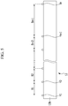
- FIG. 3 is an exploded perspective view showing a part of a rechargeable battery according to an embodiment.
- the electrode assembly 10 includes a positive electrode 11, a negative electrode 12, and a separator 13 placed between the positive electrode 11 and the negative electrode 12, which have a band shape, and has a wound structure.
- the electrode assembly 10 is wound around a winding axis (xi) while the separator 13 is interposed between the positive and negative electrodes 11 and 12, and then pressed to be flattened.
- the electrode assembly 10 includes one positive electrode 11, one negative electrode 12, and two separators 13.
- the positive electrode 11 includes a positive electrode current collector, and a positive electrode active material layer coated on the positive electrode current collector.
- the positive electrode current collector may be formed of a metal thin plate of aluminum or the like, and the positive electrode active material layer may be formed of a lithium-based oxide.
- the negative electrode 12 includes a negative electrode current collector, and a negative electrode active material layer coated on the negative electrode current collector.
- the negative electrode current collector may be formed of a metal thin plate of copper or the like, and the negative electrode active material layer may be formed of a carbon-based active material.
- the separator 13 can be formed as a porous thin film, and may be formed of a polyolefin-based resin.
- a first non-coated portion 11a and a second non-coated portion 12a are formed on the electrode assembly 10 to protrude toward the cap plate.
- the first and second non-coated portions 11a and 12a are spaced apart from each other in a width direction of the electrode assembly 10.
- the first current collecting member 41 includes an upper plate 41a bonded to the connection terminal 25, and an electrode attachment portion 41b bent toward the electrode assembly 10 and bonded to the first non-coated portion 11a.
- the electrode attachment portion 41b is bent from an end in a width direction of the upper plate 41a to be substantially parallel with the electrode assembly 10.
- the upper plate 41a has a quadrangular plate shape, and is fixed to a lower portion of the connection terminal 25 by welding.
- the upper plate 41a has a coupling hole 41e, and the connection terminal 25 and the upper plate 41a can be welded together while a protrusion formed on a lower portion of the connection terminal 25 is fitted into the coupling hole 41e.
- the upper plate 41a includes a fuse 41c having a smaller cross-sectional area compared with the periphery.
- a fuse hole 41d is formed in the fuse 41c, and thus the fuse 41c has a smaller vertical cross-sectional area compared with the periphery.
- the fuse hole 41d can be formed in substantially the center of the fuse 41c, and the fuse 41c is formed on both sides of the fuse hole 41d.
- the second current collecting member 42 includes an upper plate 42a bonded to the connection terminal 26, and an electrode attachment portion 42b bent toward the electrode assembly 10 and bonded to the second non-coated portion 12a.
- the electrode attachment portion 42b is bent from an end in a width direction of the upper plate 42a to be parallel with the electrode assembly 10.
- the upper plate 42a has a quadrangular plate shape, and is fixed to a lower portion of the connection terminal 26 by welding.
- the upper plate 42a has a coupling hole 42e, and the connection terminal 26 and the upper plate 42a can be welded together while a protrusion formed on a lower portion of the connection terminal 26 is fitted in the coupling hole 42e.
- the upper plate 42a includes a fuse 42c having a smaller cross-sectional area compared with the periphery.
- a fuse hole 42d is formed in the fuse 42c, and thus the fuse 42c has a smaller vertical cross-sectional area compared with the periphery.
- the fuse hole 42d can be formed in substantially the center of the fuse 42c, and the fuse 42c is formed on both sides of the fuse hole 42d.
- the positive electrode 11 includes a first coated portion 11b coated with a positive electrode active material, and a first non-coated portion 11a without a positive electrode active material.
- the first non-coated portion 11a includes a plurality of first electrode tabs that are stacked.
- the negative electrode 12 includes a second coated portion 12b coated with a negative electrode active material, and a second non-coated portion 12a without a negative electrode active material.
- the second non-coated portion 12a includes a plurality of second electrode tabs that are stacked.
- FIG. 4 is a developed plane view of a positive electrode according to the first embodiment in an unwound state.
- the positive electrode 11 includes a plurality of first electrode tabs T1-Tn which protrude upward from the first coated portion 11b.
- the first electrode tabs T1-Tn are spaced apart from each other in a length direction of the positive electrode 11, and the distances A1-An-1 between the first electrode tabs T1-Tn can gradually increase from the innermost portion (or innermost side) to the outermost portion (or outermost side) of the positive electrode.
- the distances A1-An-1 between the first electrode tabs T1-Tn-1 refer to spaced distances in a length direction of the positive electrode 11 and distances between the centers of neighboring first electrodes T1-Tn.
- the distance A1 between the first electrode tab T1 placed at the innermost portion and the first electrode tab T2 placed at the second innermost portion of the positive electrode 11 is less than the distance A2 between the first electrode tab T2 and the first electrode tab T3 placed at the third innermost portion of the positive electrode 11.
- the distances between adjacent ones of the first electrode tabs T1-Tn-1 can form an arithmetical progression having a common difference.
- the distances between the first electrode tabs from the first electrode T1 placed at the innermost side to the first electrode tab Tn-1 placed at the second outermost portion can form an arithmetical progression, but the distance between the first electrode tab Tn placed at the outermost side and the first electrode tab Tn-1 does not pertain to the arithmetical progression.
- the difference between the distance An-i between the first electrode tab Tn placed at the outermost side and the first electrode tab Tn-1 and the previous distance An-2 can be greater than the common difference.
- the distance between the x-th first electrode tab and the previous first electrode tab may be represented by 2 ⁇ (r + (x-1)d).
- r is the radius of an innermost circle constituting the positive electrode 11
- d is the thickness of the electrode assembly 10.
- the thickness of the electrode assembly 10 refers to the thickness of the electrode assembly that is spread without being wound, and the sum of thickness values of the positive electrode 11, the negative electrode 12, and two separators 13. Therefore, the common difference of the arithmetical progression is 2 ⁇ d.
- the distance An-i between the first electrode tabs Tn and Tn-i can be greater than any of the distances A1-An-2 between adjacent ones of the other first electrode tabs Ti-Tn-1.
- the distance An-i can be about 1.5 times to about 4 times the greatest of the distances between adjacent ones of the other first electrode tabs T1-Tn-1.
- the distance An-i can be less than about 1.5 times the above greatest distance, as long as it is greater than the common difference.
- the distance An-i can be greater than about 4 times the above greatest distance.
- the winding apparatus can recognize the first electrode tab Tn to accurately specify the position at which the winding is to be ended. That is, the winding apparatus may measure the distances between the first electrode tabs Ti-Tn using a photo-sensor or the like. If the distance between electrode tabs is determined to suddenly increase, the winding apparatus may determine the sensed first electrode tab Tn as being a tab placed at the outermost side and thus specify the position at which the winding is to be ended. Therefore, the winding of one electrode assembly 10 can be promptly ended, and the winding of another electrode assembly 10 can be started at the accurate position.
- FIG. 5 is a developed plane view of a negative electrode according to the first embodiment.
- the negative electrode 12 includes a plurality of second electrode tabs Si-Sn which protrude upwardly from the second coated portion 12b.
- the second electrode tabs Si-Sn are spaced apart from each other in a length direction of the negative electrode 12, and the distances B1-Bn-1 between the second electrode tabs Si-Sn gradually increase from the innermost portion (or innermost side) to the outermost portion (or outermost side) of the negative electrode.
- the distances B1-Bn-1 between the second electrode tabs S1-Sn-1 refer to spaced distances in a length direction of the negative electrode 12 and distances between the centers of neighboring second electrodes Si-Sn.
- the distance B1 between the second electrode tab Si placed at the innermost portion and the second electrode tab S2 placed at the second innermost portion is less than the distance B2 between the second electrode tab S2 and the second electrode tab S3 placed at the third innermost portion of the negative electrode.
- the distances between the second electrode tabs S1-Sn-1 can form an arithmetical progression having a common difference.
- the distances between the second electrode tabs from the second electrode Si placed at the innermost side to the second electrode tab Sn-1 placed second from the outside can form an arithmetical progression, but the distance between the second electrode tab Sn and the second electrode tab Sn-1 need not pertain to the arithmetical progression.
- the difference between the distance Bn-1 and the previous distance Bn-2 can be greater than the common difference.
- the distance between the x-th second electrode tab and the previous second electrode tab may be represented by 2 ⁇ (r + (x-1)d).
- r is the radius of an innermost circle constituting the negative electrode 12
- d is the thickness of the electrode assembly 10.
- the thickness of the electrode assembly 10 refers to the thickness of the electrode assembly that is spread without being wound, and the sum of thickness values of the positive electrode 11, the negative electrode 12, and two separators 13. Therefore, the common difference of the arithmetical progression is 2 ⁇ d.
- the distance Bn-1 can be greater any of the distances Bi-Bn-2 between adjacent ones of the other second electrodes S1-Sn-1.
- the distance between the second electrode tab Sn and the second electrode tab Sn-1 may be about 1.5 times to about 4 times the greatest of the distances between adjacent ones of the other second electrode tabs S1-Sn-1.
- the distance Bn-1 can be less than about 1.5 times the above greatest distance, as long as it is greater than the common difference.
- the distance Bn-1 can be greater than about 4 times the above greatest distance.
- the winding apparatus can recognize the second electrode tab Sn placed at the outermost side to accurately specify the position at which the winding is to be ended. That is, the winding apparatus may measure the distances between the second electrode tabs Si-Sn using a photo-sensor or the like. If the distance between electrode tabs is determined to suddenly increase, the winding apparatus may determine the sensed second electrode tab Sn as being a tab placed at the outermost side and thus specify the position at which the winding is to be ended. Therefore, the winding of one electrode assembly 10 can be promptly ended, and the winding of another electrode assembly 10 can be started at the accurate position.
- embodiments of the invention can provide an electrode assembly for a secondary battery, comprising: a first electrode and a second electrode which are wound with a separator placed therebetween, a plurality of first electrode tabs T1-Tn outwardly extending from the first electrode, wherein n is a natural number greater than 2, and wherein the first electrode includes first to nth portions on which the first electrode tabs T1-Tn are respectively formed, wherein the first and nth portions of the first electrode respectively define the innermost and outermost portions thereof, wherein when spread in a plane form the distance between the first electrode tab Tn placed at the outermost portion and the first electrode Tn-1 placed at the second outermost portion of the first electrode is greater than any of the distances between two adjacent ones of the other first electrode tabs T1-Tn-1.
- the first electrode includes a first coated portion coated with an active material, wherein the plurality of first electrode tabs T1-Tn are not coated with an active material and protrude outwardly from the first coated portion.
- the distances between the first electrode tabs may be the distances along a spiral about the winding axis.
- Embodiments of the invention can also provide a method of manufacturing an electrode assembly for a secondary battery, comprising: providing a first electrode including a first coated portion coated with an active material, and a plurality of first electrode tabs T1-Tn outwardly extending from the first electrode, wherein n is a natural number greater than 2, wherein the first electrode, when spread in a plane form, includes first to nth portions on which the first electrode tabs T1-Tn are respectively formed, wherein the first and nth portions of the first electrode respectively define the innermost and outermost portions thereof, wherein the distance between the first electrode tab Tn placed at the outermost portion and the first electrode Tn-1 placed at the second outermost portion of the first electrode is greater than any of the distances between two adjacent ones of the other first electrode tabs T1-Tn-1; winding the first electrode with a second electrode with a separator placed therebetween; wherein the winding comprises: detecting the distances between the first electrode tabs; and stopping the winding when the distance between the first electrode tab
- the method further comprises using a photosensor to detect the distances between the first electrode tab.
- the method further comprises recognising the distance between the first electrode tab Tn placed at the outermost portion and the first electrode Tn-1 placed at the second outermost portion of the first electrode by detecting an increase in distance between adjacent first electrode tabs above a threshold.
- Embodiments of the invention can also provide a rechargeable battery, comprising: an electrode assembly including a first electrode and a second electrode wound with a separator placed therebetween; a case containing the electrode assembly; and a cap plate combined with the case, wherein the electrode assembly is according to any one of the above mentioned embodiments
Description
- The described technology generally relates to an electrode assembly and a secondary battery including the electrode assembly.
- A rechargeable (or secondary) battery can be charged and discharged multiple times, unlike a primary battery. A low-capacity rechargeable battery is used for small portable electronic devices such as a portable phone, a smartphone, a tablet computer, a notebook computer, and a camcorder. A high-capacity rechargeable battery (most often used with an array of batteries or battery cells) is widely used as a power source for driving a motor for a hybrid vehicle or an electric vehicle.
- Recently, a high-output rechargeable battery using a non-aqueous electrolyte solution with high energy density has been developed. The high-output rechargeable battery is configured as a high-capacity rechargeable battery in which a plurality of rechargeable batteries are connected in series so as to be used in driving a device requiring high power, for example, a motor for an electric vehicle.
- In addition, one high-capacity rechargeable battery generally includes a plurality of rechargeable batteries which are connected in series, and the rechargeable battery may have a cylindrical or angular shape. In addition, the rechargeable battery has an electrode assembly implementing charging and discharging. The electrode assembly includes a positive electrode, a negative electrode, and a separator interposed between the positive and negative electrodes. The electrode assembly is often formed with a structure in which a plurality of positive electrode plates and negative electrode plates are stacked or a structure in which band-shaped positive and negative electrodes are wound.
-
EP1207565 discloses a battery comprising an electricity-generating element comprising a strip-form positive electrode (11), a strip-form negative electrode (12), and a strip-form separator (13), said positive electrode and said negative electrode being spirally wound through said separator and said positive electrode and said negative electrode respectively having current collecting lugs (11a,12a) protruding from a side thereof.JP2011-171079 claim 1 and relates to an electrode assembly. One inventive aspect relates to an electrode assembly and a secondary battery having an electrode tab. - Another aspect is an electrode assembly capable of being easily wound, and a rechargeable battery including the same.
- According to at least one of the disclosed embodiments, the point at which the winding of the electrode assembly is ended can be easily detected using the electrode tab placed at the outermost side of the electrode assembly.
- According to an aspect of the invention, there is provided an electrode assembly as set out in
claim 1. Preferred features are set out inclaims 2 to 6. - According to an aspect of the invention, there is provided a rechargeable battery as set out in claim 7. Preferred features are set out in claims 8 to 9.
-
FIG. 1 is a perspective view showing a rechargeable battery according to a first embodiment. -
FIG. 2 is a cross-sectional view taken along line II - II inFIG. 2 . -
FIG. 3 is an exploded perspective view showing a part of the rechargeable battery according to the first embodiment. -
FIG. 4 is a developed plane view of a positive electrode according to the first embodiment. -
FIG. 5 is a developed plane view of a negative electrode according to the first embodiment. - Generally, in a secondary battery, it is important to align protruding electrode tabs when a positive electrode, a negative electrode, and a separator are stacked and wound, and thus, the start and end points of the winding need to be accurately checked during manufacture.
- Embodiments will be described more fully hereinafter with reference to the accompanying drawings, in which exemplary embodiments are shown. However, the present invention may be embodied in many different forms, and is not limited to the exemplary embodiments described herein. In addition, like reference numerals refer to like elements throughout the specification and drawings. In this disclosure, the term "substantially" includes the meanings of completely, almost completely or to any significant degree under some applications and in accordance with those skilled in the art. Moreover, "formed on" can also mean "formed over." The term "connected" includes an electrical connection.
-
FIG. 1 is a perspective view showing arechargeable battery 101 according to an embodiment, andFIG. 2 is a cross-sectional view taken along line II - II inFIG. 2 . - Referring to
FIGS. 1 and2 , therechargeable battery 101 includes anelectrode assembly 10 in which a positive electrode (first electrode) 11 and a negative electrode (second electrode) 12 are wound with aseparator 13 interposed therebetween, acase 27 containing theelectrode assembly 10, and acap assembly 30 connected to an opening of thecase 27. - The
rechargeable battery 101 will be described by exemplifying a lithium ion rechargeable battery with an angular shape. However, embodiments of the present invention are not limited thereto, and may be applied to various types of batteries, such as a lithium polymer battery or a cylindrical shaped battery. In addition, therechargeable battery 101 can be a high-output rectangular shaped battery, and may be formed as, particularly, a battery for powering a motor used to start a vehicle. Since such battery requires momentary high power, a structure in which electrode tabs protrude upward is favorable, as in the present embodiment. However, it is very difficult to accurately align electrode tabs in cases of the structure in which the electrode tabs protrude upwardly. In order to accurately align the electrode tabs, a point at which winding is started and a point at which the winding is ended need to be accurately specified, and thus the electrode tabs can be accurately stacked without missing each other. - The
case 27 can have a substantially cuboid shape, and an opening is formed in one surface thereof. Thecase 27 may be formed of a metal, such as aluminum or stainless steel. - The
cap assembly 30 includes acap plate 31 covering the opening of thecase 27, afirst terminal 21 protruding outwardly from thecap plate 31 and electrically connected to thepositive electrode 11, and asecond terminal 22 protruding outwardly from thecap plate 31 and electrically connected to thenegative electrode 12. - The
cap plate 31 can have a long plate shape that is lengthened in one direction, and is connected to the opening of thecase 27. Thecap plate 31 is equipped with asealing stopper 38, which is installed at anelectrolyte inlet 32, and avent plate 34, which is installed at avent hole 39 and has anotch 39a which can be opened at a predetermined pressure. The first andsecond terminals cap plate 31. - The
first terminal 21 is electrically connected to thepositive electrode 11 via a firstcurrent collecting member 41, and thesecond terminal 22 is electrically connected to thenegative electrode 12 via a secondcurrent collecting member 42. However, embodiments of the present invention are not limited thereto, and thefirst terminal 21 may be electrically connected to the negative electrode and thesecond terminal 22 may be electrically connected to the positive electrode. - The
first terminal 21 can have a rectangular plate shape. Thefirst terminal 21 is electrically connected to thepositive electrode 11 via aconnection terminal 25 bonded to the firstcurrent collecting member 41. Theconnection terminal 25 can have a pillar shape, and can be attached to thefirst terminal 21 by welding while an upper end of theconnection terminal 25 is fitted into thefirst terminal 21. In addition, the upper end of theconnection terminal 25 can be attached to the first current collectingmember 41 by welding, and the first current collectingmember 41 electrically connects theconnection terminal 25 and thepositive electrode 11. - A sealing
gasket 59 is inserted into a hole through which the terminal passes, between thefirst terminal 21 and thecap plate 31, and alower insulation member 43 supporting the firstcurrent collecting member 41 is formed below thecap plate 31. - A
connection member 58 electrically connecting thefirst terminal 21 and thecap plate 31 is formed below thefirst terminal 21. Hence, thecap plate 31 and thecase 27 are positively charged. - The
second terminal 22 can have a rectangular plate shape. Thesecond terminal 22 is electrically connected to thenegative electrode 12 via aconnection terminal 26 bonded to the secondcurrent collecting member 42. An upper end of theconnection terminal 26 is attached to thesecond terminal 22 while passing through thefirst cap plate 31 and thesecond terminal 22. - The
connection terminal 26 can have a pillar shape, and can be attached to thesecond terminal 22 while an upper end of theconnection terminal 26 is fitted into thesecond terminal 22. In addition, the upper end of theconnection terminal 26 can be attached to the second current collectingmember 42 by welding, and the second current collectingmember 42 electrically connects theconnection terminal 26 and thenegative electrode 12. - A sealing
gasket 55 is inserted into a hole through which theconnection terminal 26 passes, between thesecond terminal 22 and thecap plate 31, and alower insulation member 45 for insulating the second current collectingmember 42 and thesecond terminal 22 from each other by thecap plate 31 is formed below thecap plate 31. - Meanwhile, a short circuit protrusion protruding toward a
short circuit hole 37 is formed on a lower portion of thesecond terminal 22. Thesecond terminal 22 is extended in one direction to cover theshort circuit hole 37. Anupper insulation member 54 electrically insulating thesecond terminal 22 and thecap plate 31 is formed between thesecond terminal 22 and thecap plate 31. - The
cap assembly 30 includes ashort circuit member 56 for short circuiting thepositive electrode 11 and thenegative electrode 12, theshort circuit member 56 is electrically connected to thecap plate 31, and is transformed to be connected to thesecond terminal 22 when the inner pressure of therechargeable battery 101 rises. - The
cap plate 31 has theshort circuit hole 37, and theshort circuit member 56 is placed between theupper insulation member 54 and thecap plate 31 in theshort circuit hole 37. In addition, thesecond terminal 22 is placed in theshort circuit hole 37 to cover theshort circuit hole 37. Theshort circuit member 56 includes a curved portion which is bent in an arc shape to be convex downward, and an edge portion formed outside the curved portion and fixed to thecap plate 31. - When a gas is generated due to an abnormal reaction inside the secondary rechargeable battery, the inner pressure of the secondary rechargeable battery rises. When the inner pressure of the secondary rechargeable battery is higher than the predetermined pressure, the curved portion is transformed to be convex upward, and the short circuit protrusion and the
short circuit member 56 are touched to cause a short circuit. -
FIG. 3 is an exploded perspective view showing a part of a rechargeable battery according to an embodiment. Referring toFIGS. 2 and3 , theelectrode assembly 10 includes apositive electrode 11, anegative electrode 12, and aseparator 13 placed between thepositive electrode 11 and thenegative electrode 12, which have a band shape, and has a wound structure. Theelectrode assembly 10 is wound around a winding axis (xi) while theseparator 13 is interposed between the positive andnegative electrodes electrode assembly 10 includes onepositive electrode 11, onenegative electrode 12, and twoseparators 13. - The
positive electrode 11 includes a positive electrode current collector, and a positive electrode active material layer coated on the positive electrode current collector. The positive electrode current collector may be formed of a metal thin plate of aluminum or the like, and the positive electrode active material layer may be formed of a lithium-based oxide. Thenegative electrode 12 includes a negative electrode current collector, and a negative electrode active material layer coated on the negative electrode current collector. The negative electrode current collector may be formed of a metal thin plate of copper or the like, and the negative electrode active material layer may be formed of a carbon-based active material. Theseparator 13 can be formed as a porous thin film, and may be formed of a polyolefin-based resin. - A first
non-coated portion 11a and a secondnon-coated portion 12a are formed on theelectrode assembly 10 to protrude toward the cap plate. The first and secondnon-coated portions electrode assembly 10. - The first current collecting
member 41 includes anupper plate 41a bonded to theconnection terminal 25, and anelectrode attachment portion 41b bent toward theelectrode assembly 10 and bonded to the firstnon-coated portion 11a. Theelectrode attachment portion 41b is bent from an end in a width direction of theupper plate 41a to be substantially parallel with theelectrode assembly 10. - In some embodiments, the
upper plate 41a has a quadrangular plate shape, and is fixed to a lower portion of theconnection terminal 25 by welding. Theupper plate 41a has acoupling hole 41e, and theconnection terminal 25 and theupper plate 41a can be welded together while a protrusion formed on a lower portion of theconnection terminal 25 is fitted into thecoupling hole 41e. - The
upper plate 41a includes afuse 41c having a smaller cross-sectional area compared with the periphery. Afuse hole 41d is formed in thefuse 41c, and thus thefuse 41c has a smaller vertical cross-sectional area compared with the periphery. Thefuse hole 41d can be formed in substantially the center of thefuse 41c, and thefuse 41c is formed on both sides of thefuse hole 41d. - The second current collecting
member 42 includes anupper plate 42a bonded to theconnection terminal 26, and anelectrode attachment portion 42b bent toward theelectrode assembly 10 and bonded to the secondnon-coated portion 12a. Theelectrode attachment portion 42b is bent from an end in a width direction of theupper plate 42a to be parallel with theelectrode assembly 10. - In some embodiments, the
upper plate 42a has a quadrangular plate shape, and is fixed to a lower portion of theconnection terminal 26 by welding. Theupper plate 42a has acoupling hole 42e, and theconnection terminal 26 and theupper plate 42a can be welded together while a protrusion formed on a lower portion of theconnection terminal 26 is fitted in thecoupling hole 42e. - The
upper plate 42a includes afuse 42c having a smaller cross-sectional area compared with the periphery. Afuse hole 42d is formed in thefuse 42c, and thus thefuse 42c has a smaller vertical cross-sectional area compared with the periphery. Thefuse hole 42d can be formed in substantially the center of thefuse 42c, and thefuse 42c is formed on both sides of thefuse hole 42d. - The
positive electrode 11 includes a firstcoated portion 11b coated with a positive electrode active material, and a firstnon-coated portion 11a without a positive electrode active material. The firstnon-coated portion 11a includes a plurality of first electrode tabs that are stacked. In addition, thenegative electrode 12 includes a secondcoated portion 12b coated with a negative electrode active material, and a secondnon-coated portion 12a without a negative electrode active material. The secondnon-coated portion 12a includes a plurality of second electrode tabs that are stacked. -
FIG. 4 is a developed plane view of a positive electrode according to the first embodiment in an unwound state. - Referring to
FIG. 4 , thepositive electrode 11 includes a plurality of first electrode tabs T1-Tn which protrude upward from the firstcoated portion 11b. - The first electrode tabs T1-Tn are spaced apart from each other in a length direction of the
positive electrode 11, and the distances A1-An-1 between the first electrode tabs T1-Tn can gradually increase from the innermost portion (or innermost side) to the outermost portion (or outermost side) of the positive electrode. In the discussion of the present embodiment, the distances A1-An-1 between the first electrode tabs T1-Tn-1 refer to spaced distances in a length direction of thepositive electrode 11 and distances between the centers of neighboring first electrodes T1-Tn. - Thus, the distance A1 between the first electrode tab T1 placed at the innermost portion and the first electrode tab T2 placed at the second innermost portion of the
positive electrode 11 is less than the distance A2 between the first electrode tab T2 and the first electrode tab T3 placed at the third innermost portion of thepositive electrode 11. - The distances between adjacent ones of the first electrode tabs T1-Tn-1 can form an arithmetical progression having a common difference. However, the distances between the first electrode tabs from the first electrode T1 placed at the innermost side to the first electrode tab Tn-1 placed at the second outermost portion can form an arithmetical progression, but the distance between the first electrode tab Tn placed at the outermost side and the first electrode tab Tn-1 does not pertain to the arithmetical progression. For example, the difference between the distance An-i between the first electrode tab Tn placed at the outermost side and the first electrode tab Tn-1 and the previous distance An-2 can be greater than the common difference.
- Among the first electrode tabs from the first electrode tab T1 placed at the innermost side to the first electrode tab Tn-1 placed second from the outside, the distance between the x-th first electrode tab and the previous first electrode tab may be represented by 2π(r + (x-1)d). Here, r is the radius of an innermost circle constituting the
positive electrode 11, and d is the thickness of theelectrode assembly 10. - Here, the thickness of the
electrode assembly 10 refers to the thickness of the electrode assembly that is spread without being wound, and the sum of thickness values of thepositive electrode 11, thenegative electrode 12, and twoseparators 13. Therefore, the common difference of the arithmetical progression is 2πd. - The distance An-i between the first electrode tabs Tn and Tn-ican be greater than any of the distances A1-An-2 between adjacent ones of the other first electrode tabs Ti-Tn-1. The distance An-i can be about 1.5 times to about 4 times the greatest of the distances between adjacent ones of the other first electrode tabs T1-Tn-1. However, depending on the embodiments, the distance An-i can be less than about 1.5 times the above greatest distance, as long as it is greater than the common difference. Furthermore, depending on the embodiments, the distance An-i can be greater than about 4 times the above greatest distance.
- Since the distance between the two outermost electrode tabs Tn and Tn-1 is greater than any other distance, the winding apparatus can recognize the first electrode tab Tn to accurately specify the position at which the winding is to be ended. That is, the winding apparatus may measure the distances between the first electrode tabs Ti-Tn using a photo-sensor or the like. If the distance between electrode tabs is determined to suddenly increase, the winding apparatus may determine the sensed first electrode tab Tn as being a tab placed at the outermost side and thus specify the position at which the winding is to be ended. Therefore, the winding of one
electrode assembly 10 can be promptly ended, and the winding of anotherelectrode assembly 10 can be started at the accurate position. -
FIG. 5 is a developed plane view of a negative electrode according to the first embodiment. - Referring to
FIG. 5 , thenegative electrode 12 includes a plurality of second electrode tabs Si-Sn which protrude upwardly from the secondcoated portion 12b. - The second electrode tabs Si-Sn are spaced apart from each other in a length direction of the
negative electrode 12, and the distances B1-Bn-1 between the second electrode tabs Si-Sn gradually increase from the innermost portion (or innermost side) to the outermost portion (or outermost side) of the negative electrode. In the discussion of the present embodiment, the distances B1-Bn-1 between the second electrode tabs S1-Sn-1 refer to spaced distances in a length direction of thenegative electrode 12 and distances between the centers of neighboring second electrodes Si-Sn. - Thus, the distance B1 between the second electrode tab Si placed at the innermost portion and the second electrode tab S2 placed at the second innermost portion is less than the distance B2 between the second electrode tab S2 and the second electrode tab S3 placed at the third innermost portion of the negative electrode.
- The distances between the second electrode tabs S1-Sn-1 can form an arithmetical progression having a common difference. However, the distances between the second electrode tabs from the second electrode Si placed at the innermost side to the second electrode tab Sn-1 placed second from the outside can form an arithmetical progression, but the distance between the second electrode tab Sn and the second electrode tab Sn-1 need not pertain to the arithmetical progression. The difference between the distance Bn-1 and the previous distance Bn-2 can be greater than the common difference.
- Among the second electrode tabs from the second electrode tab Si placed at the innermost side to the second electrode tab Sn-1 placed at the second outermost portion, the distance between the x-th second electrode tab and the previous second electrode tab may be represented by 2π(r + (x-1)d). Here, r is the radius of an innermost circle constituting the
negative electrode 12, and d is the thickness of theelectrode assembly 10. - Here, the thickness of the
electrode assembly 10 refers to the thickness of the electrode assembly that is spread without being wound, and the sum of thickness values of thepositive electrode 11, thenegative electrode 12, and twoseparators 13. Therefore, the common difference of the arithmetical progression is 2πd. - The distance Bn-1 can be greater any of the distances Bi-Bn-2 between adjacent ones of the other second electrodes S1-Sn-1. The distance between the second electrode tab Sn and the second electrode tab Sn-1 may be about 1.5 times to about 4 times the greatest of the distances between adjacent ones of the other second electrode tabs S1-Sn-1. However, depending on the embodiments, the distance Bn-1 can be less than about 1.5 times the above greatest distance, as long as it is greater than the common difference. Furthermore, depending on the embodiments, the distance Bn-1 can be greater than about 4 times the above greatest distance.
- Since the distance between the two outermost electrode tabs Sn and Sn-1 is greater than any other distance, the winding apparatus can recognize the second electrode tab Sn placed at the outermost side to accurately specify the position at which the winding is to be ended. That is, the winding apparatus may measure the distances between the second electrode tabs Si-Sn using a photo-sensor or the like. If the distance between electrode tabs is determined to suddenly increase, the winding apparatus may determine the sensed second electrode tab Sn as being a tab placed at the outermost side and thus specify the position at which the winding is to be ended. Therefore, the winding of one
electrode assembly 10 can be promptly ended, and the winding of anotherelectrode assembly 10 can be started at the accurate position. - As discussed, embodiments of the invention can provide an electrode assembly for a secondary battery, comprising: a first electrode and a second electrode which are wound with a separator placed therebetween, a plurality of first electrode tabs T1-Tn outwardly extending from the first electrode, wherein n is a natural number greater than 2, and wherein the first electrode includes first to nth portions on which the first electrode tabs T1-Tn are respectively formed, wherein the first and nth portions of the first electrode respectively define the innermost and outermost portions thereof, wherein when spread in a plane form the distance between the first electrode tab Tn placed at the outermost portion and the first electrode Tn-1 placed at the second outermost portion of the first electrode is greater than any of the distances between two adjacent ones of the other first electrode tabs T1-Tn-1. In some embodiments, the first electrode includes a first coated portion coated with an active material, wherein the plurality of first electrode tabs T1-Tn are not coated with an active material and protrude outwardly from the first coated portion.
- The distances between the first electrode tabs may be the distances along a spiral about the winding axis.
- Embodiments of the invention can also provide a method of manufacturing an electrode assembly for a secondary battery, comprising: providing a first electrode including a first coated portion coated with an active material, and a plurality of first electrode tabs T1-Tn outwardly extending from the first electrode, wherein n is a natural number greater than 2, wherein the first electrode, when spread in a plane form, includes first to nth portions on which the first electrode tabs T1-Tn are respectively formed, wherein the first and nth portions of the first electrode respectively define the innermost and outermost portions thereof, wherein the distance between the first electrode tab Tn placed at the outermost portion and the first electrode Tn-1 placed at the second outermost portion of the first electrode is greater than any of the distances between two adjacent ones of the other first electrode tabs T1-Tn-1; winding the first electrode with a second electrode with a separator placed therebetween; wherein the winding comprises: detecting the distances between the first electrode tabs; and stopping the winding when the distance between the first electrode tab Tn placed at the outermost portion and the first electrode Tn-1 placed at the second outermost portion of the first electrode is recognised.
- In some embodiments, the method further comprises using a photosensor to detect the distances between the first electrode tab.
- In some embodiments, the method further comprises recognising the distance between the first electrode tab Tn placed at the outermost portion and the first electrode Tn-1 placed at the second outermost portion of the first electrode by detecting an increase in distance between adjacent first electrode tabs above a threshold.
- Embodiments of the invention can also provide a rechargeable battery, comprising: an electrode assembly including a first electrode and a second electrode wound with a separator placed therebetween; a case containing the electrode assembly; and a cap plate combined with the case, wherein the electrode assembly is according to any one of the above mentioned embodiments
- While the inventive technology has been described in connection with what is presently considered to be practical exemplary embodiments, it is to be understood that the invention is not limited to the disclosed embodiments, but, on the contrary, is intended to cover various modifications and equivalent arrangements included within the scope of the appended claims.
Claims (9)
- An electrode assembly (10) for a secondary battery (101), comprising:a first electrode (11) and a second electrode (12) which are wound with a separator (13) placed therebetween,a plurality of first electrode tabs T1-Tn extending from the first electrode, wherein n is a natural number greater than 2, andwherein the first electrode includes first to nth portions on which the first electrode tabs T1-Tn are respectively formed, wherein the first and nth portions of the first electrode respectively define the innermost and outermost portions thereof, wherein, when spread in a plane form, the distance between the first electrode tab Tn placed at the outermost portion and the first electrode tab Tn-1 placed at the second outermost portion of the first electrode is greater than any of the distances between two adjacent ones of the other first electrode tabs T1-Tn-1wherein the distances between two adjacent ones of the first electrode tabs gradually increase from the innermost portion to the second outermost portion of the first electrode, wherein the distances between two adjacent ones of the first electrode tabs T1-Tn-1 form an arithmetical progression having a common difference, and characterised in that the difference between the distance between the first electrode tab Tn and the first electrode tab Tn-1 and the distance between the first electrode tab Tn-1 and the first electrode tab Tn-2 is greater than the common difference.
- The electrode assembly of claim 1, wherein the first electrode includes a first coated portion coated with an active material, wherein the plurality of first electrode tabs T1-Tn are not coated with an active material and protrude from the first coated portion.
- The electrode assembly of claim 1, wherein the common difference is 2πd when the thickness of the electrode assembly in a spread state is represented by d.
- The electrode assembly of any one of claims 1 to 3, wherein the distance between the first electrode tab Tn placed at the outermost portion and the first electrode tab Tn-1 placed at the second outermost portion of the first electrode is about 1.5 times to about 4 times the greatest of the distances between two adjacent ones of the other first electrode tabs T1-Tn-1.
- The electrode assembly of any one of claims 1 to 4, wherein the second electrode includes a second coated portion coated with an active material, and a plurality of second electrode tabs Y1-Yn not coated with an active material and protruding from the second coated portion, and
wherein the second electrode, when spread in a plane form, includes first to nth portions on which the second electrode tabs Y1-Yn are respectively formed, wherein n is a natural number greater than 2, wherein the first and nth portions of the second electrode respectively define the innermost and outermost portions thereof, wherein the distance between the second electrode tab Yn placed at the outermost portion and the second electrode tab Yn-1 placed at the second outermost portion of the second electrode is greater than any of the distances between two adjacent ones of the other second electrode tabs Y1-Yn-1. - The electrode assembly of claim 5, wherein the distances between adjacent ones of the second electrode tabs Y1-Yn-1 gradually increase from the innermost portion to the second outermost portion of the second electrode.
- A rechargeable battery, comprising:an electrode assembly including a first electrode and a second electrode wound with a separator placed therebetween;a case containing the electrode assembly; anda cap plate combined with the case,wherein the electrode assembly is according to any one of claims 1 to 6.
- The rechargeable battery of claim 7, wherein a first terminal electrically
connected to the first electrode is installed on the cap plate, a connection terminal formed in a pillar shape being fitted into the first terminal, and
wherein the first terminal is electrically connected to the first electrode via a first current collecting member, the first current collecting member including an upper plate bonded to the connection terminal and an electrode attachment portion bent from the upper plate toward the electrode assembly to be bonded to the first electrode tab. =new - The rechargeable battery of claim 7 or 8, wherein the battery is configured to drive a motor to start a vehicle.
Applications Claiming Priority (1)
| Application Number | Priority Date | Filing Date | Title |
|---|---|---|---|
| KR1020150013814A KR102368089B1 (en) | 2015-01-28 | 2015-01-28 | Electrode assembly and rechargeable battery having electrode tap |
Publications (3)
| Publication Number | Publication Date |
|---|---|
| EP3051610A2 EP3051610A2 (en) | 2016-08-03 |
| EP3051610A3 EP3051610A3 (en) | 2016-11-09 |
| EP3051610B1 true EP3051610B1 (en) | 2018-09-12 |
Family
ID=55070878
Family Applications (1)
| Application Number | Title | Priority Date | Filing Date |
|---|---|---|---|
| EP16150338.8A Active EP3051610B1 (en) | 2015-01-28 | 2016-01-06 | Electrode assembly and rechargeable battery having electrode tab |
Country Status (5)
| Country | Link |
|---|---|
| US (1) | US9786897B2 (en) |
| EP (1) | EP3051610B1 (en) |
| JP (1) | JP6641116B2 (en) |
| KR (1) | KR102368089B1 (en) |
| CN (1) | CN105826514B (en) |
Families Citing this family (17)
| Publication number | Priority date | Publication date | Assignee | Title |
|---|---|---|---|---|
| KR102368092B1 (en) * | 2015-01-28 | 2022-02-24 | 삼성에스디아이 주식회사 | Electrode assembly and rechargeable battery having electrode tap |
| KR102368090B1 (en) * | 2015-01-28 | 2022-02-24 | 삼성에스디아이 주식회사 | Electrode assembly and rechargeable battery having electrode ta1p |
| JP6935798B2 (en) * | 2016-07-29 | 2021-09-15 | 三洋電機株式会社 | How to manufacture a secondary battery |
| CN109417154B (en) * | 2016-07-29 | 2022-01-04 | 三洋电机株式会社 | Secondary battery |
| KR20180070078A (en) | 2016-12-16 | 2018-06-26 | 권은주 | A manufacturing method of potato Ongsimi |
| JP6802980B2 (en) * | 2017-03-23 | 2020-12-23 | トヨタ自動車株式会社 | Non-aqueous electrolyte secondary battery |
| KR102316338B1 (en) * | 2017-04-14 | 2021-10-22 | 주식회사 엘지에너지솔루션 | Electrode assembly |
| EP3396737A1 (en) * | 2017-04-27 | 2018-10-31 | Lithium Energy and Power GmbH & Co. KG | Battery cell |
| JP7035348B6 (en) * | 2017-06-29 | 2022-04-01 | 三洋電機株式会社 | Square secondary battery and its manufacturing method |
| US10680228B2 (en) | 2017-09-12 | 2020-06-09 | Chongqing Jinkang New Energy Vehicle Co., Ltd. | Electric vehicle battery current collector |
| WO2019104720A1 (en) * | 2017-12-01 | 2019-06-06 | 宁德新能源科技有限公司 | Coiled battery cell |
| JP6962167B2 (en) * | 2017-12-12 | 2021-11-05 | 三洋電機株式会社 | Rechargeable battery |
| JP7132672B2 (en) * | 2018-07-20 | 2022-09-07 | レプト・バッテロ・エナジー・カンパニー・リミテッド | Electrode sheet and battery cell for wound type lithium ion battery, and manufacturing method thereof |
| JP7329538B2 (en) * | 2018-12-19 | 2023-08-18 | 三洋電機株式会社 | Secondary battery and manufacturing method thereof |
| KR102044126B1 (en) | 2019-08-06 | 2019-12-05 | 권은주 | A manufacturing method of potato Ongsimi |
| CN115280589A (en) | 2020-03-26 | 2022-11-01 | 三洋电机株式会社 | Secondary battery |
| JP7463341B2 (en) * | 2021-12-28 | 2024-04-08 | プライムプラネットエナジー&ソリューションズ株式会社 | Battery manufacturing method |
Family Cites Families (16)
| Publication number | Priority date | Publication date | Assignee | Title |
|---|---|---|---|---|
| US2187466A (en) | 1938-04-08 | 1940-01-16 | Stratford Dev Corp | Apparatus for treating hydrocarbon oils |
| JP4797236B2 (en) | 2000-11-17 | 2011-10-19 | 株式会社Gsユアサ | battery |
| JP2002164044A (en) * | 2000-11-24 | 2002-06-07 | Nec Corp | Electrode wound-type battery and method of manufacturing the same |
| JP5127271B2 (en) * | 2007-03-12 | 2013-01-23 | 株式会社東芝 | Winding electrode battery and manufacturing method thereof |
| JP2010118315A (en) * | 2008-11-14 | 2010-05-27 | Toshiba Corp | Nonaqueous electrolyte battery |
| KR101137372B1 (en) * | 2009-09-18 | 2012-04-20 | 삼성에스디아이 주식회사 | Method of manufacturing electrode assembly for rechargeable battery |
| JP2011081964A (en) * | 2009-10-05 | 2011-04-21 | Toshiba Corp | Manufacturing device of electrode, manufacturing method of electrode, electrode, and nonaqueous electrolyte battery |
| JP2011171079A (en) * | 2010-02-17 | 2011-09-01 | Toshiba Corp | Battery cell |
| KR101147237B1 (en) * | 2010-07-12 | 2012-05-18 | 삼성에스디아이 주식회사 | Electrode assembly and rechargeable battery including the same |
| JP5749034B2 (en) * | 2011-02-18 | 2015-07-15 | 株式会社東芝 | battery |
| JP5912271B2 (en) * | 2011-03-16 | 2016-04-27 | トヨタ自動車株式会社 | Secondary battery |
| CN103477490B (en) * | 2011-12-23 | 2015-12-02 | 株式会社Lg化学 | With active material with the winding-typed electrode assembly of pattern application and the secondary cell comprising it |
| KR101666873B1 (en) * | 2012-11-23 | 2016-10-17 | 삼성에스디아이 주식회사 | Electrode assembly, and rechargeable battery having thereof |
| JP6162431B2 (en) * | 2013-02-28 | 2017-07-12 | 株式会社東芝 | battery |
| KR102368092B1 (en) * | 2015-01-28 | 2022-02-24 | 삼성에스디아이 주식회사 | Electrode assembly and rechargeable battery having electrode tap |
| KR102368090B1 (en) * | 2015-01-28 | 2022-02-24 | 삼성에스디아이 주식회사 | Electrode assembly and rechargeable battery having electrode ta1p |
-
2015
- 2015-01-28 KR KR1020150013814A patent/KR102368089B1/en active IP Right Grant
- 2015-08-03 JP JP2015153157A patent/JP6641116B2/en active Active
- 2015-12-15 US US14/969,803 patent/US9786897B2/en active Active
-
2016
- 2016-01-06 EP EP16150338.8A patent/EP3051610B1/en active Active
- 2016-01-21 CN CN201610041116.9A patent/CN105826514B/en active Active
Non-Patent Citations (1)
| Title |
|---|
| None * |
Also Published As
| Publication number | Publication date |
|---|---|
| EP3051610A3 (en) | 2016-11-09 |
| JP2016139596A (en) | 2016-08-04 |
| CN105826514A (en) | 2016-08-03 |
| JP6641116B2 (en) | 2020-02-05 |
| US9786897B2 (en) | 2017-10-10 |
| KR20160092870A (en) | 2016-08-05 |
| EP3051610A2 (en) | 2016-08-03 |
| CN105826514B (en) | 2020-12-08 |
| US20160218343A1 (en) | 2016-07-28 |
| KR102368089B1 (en) | 2022-02-24 |
Similar Documents
| Publication | Publication Date | Title |
|---|---|---|
| EP3051610B1 (en) | Electrode assembly and rechargeable battery having electrode tab | |
| JP6491448B2 (en) | Secondary battery and battery module | |
| JP4519063B2 (en) | Secondary battery | |
| KR101155888B1 (en) | Rechargeable battery | |
| KR101683210B1 (en) | Rechargeable battery | |
| KR102314081B1 (en) | Rechargeable battery having tap | |
| EP1906469A1 (en) | Battery Pack | |
| EP2362465A2 (en) | Rechargeable battery | |
| US9825274B2 (en) | Electrode assembly and rechargeable battery having electrode tab | |
| KR101711992B1 (en) | Rechargeable battery having upper insulator member | |
| EP2793295A2 (en) | Rechargeable battery | |
| KR102279223B1 (en) | Electrode assembly having protection tape and rechargeable battery having thereof | |
| US20090208825A1 (en) | Electrode assembly and secondary battery using the same | |
| US8980463B2 (en) | Secondary battery and cover assembly employed therein | |
| KR102373537B1 (en) | Battery module | |
| US9799875B2 (en) | Electrode assembly and rechargeable battery having electrode tab | |
| KR102232532B1 (en) | Rechargeable battery having short protrusion | |
| EP2860796A2 (en) | Rechargeable battery having short-circuit protrusion | |
| KR20160138782A (en) | Rechageable battery | |
| US9397329B2 (en) | Rechargeable battery having lead tab | |
| KR100889769B1 (en) | Prismatic type lithium secondary battery and the fabrication method of the same | |
| KR20150102631A (en) | Rechargeable battery having top insulation member | |
| EP2933857B1 (en) | Battery pack | |
| US20170117528A1 (en) | Rechargeable battery | |
| EP4220795A2 (en) | Cylindrical secondary battery |
Legal Events
| Date | Code | Title | Description |
|---|---|---|---|
| PUAI | Public reference made under article 153(3) epc to a published international application that has entered the european phase |
Free format text: ORIGINAL CODE: 0009012 |
|
| AK | Designated contracting states |
Kind code of ref document: A2 Designated state(s): AL AT BE BG CH CY CZ DE DK EE ES FI FR GB GR HR HU IE IS IT LI LT LU LV MC MK MT NL NO PL PT RO RS SE SI SK SM TR |
|
| AX | Request for extension of the european patent |
Extension state: BA ME |
|
| PUAL | Search report despatched |
Free format text: ORIGINAL CODE: 0009013 |
|
| AK | Designated contracting states |
Kind code of ref document: A3 Designated state(s): AL AT BE BG CH CY CZ DE DK EE ES FI FR GB GR HR HU IE IS IT LI LT LU LV MC MK MT NL NO PL PT RO RS SE SI SK SM TR |
|
| AX | Request for extension of the european patent |
Extension state: BA ME |
|
| RIC1 | Information provided on ipc code assigned before grant |
Ipc: H01M 10/0587 20100101ALI20160930BHEP Ipc: H01M 4/70 20060101ALI20160930BHEP Ipc: H01M 10/052 20100101ALI20160930BHEP Ipc: H01M 2/26 20060101AFI20160930BHEP Ipc: H01M 10/04 20060101ALI20160930BHEP |
|
| STAA | Information on the status of an ep patent application or granted ep patent |
Free format text: STATUS: REQUEST FOR EXAMINATION WAS MADE |
|
| 17P | Request for examination filed |
Effective date: 20170509 |
|
| RBV | Designated contracting states (corrected) |
Designated state(s): AL AT BE BG CH CY CZ DE DK EE ES FI FR GB GR HR HU IE IS IT LI LT LU LV MC MK MT NL NO PL PT RO RS SE SI SK SM TR |
|
| GRAP | Despatch of communication of intention to grant a patent |
Free format text: ORIGINAL CODE: EPIDOSNIGR1 |
|
| STAA | Information on the status of an ep patent application or granted ep patent |
Free format text: STATUS: GRANT OF PATENT IS INTENDED |
|
| RIC1 | Information provided on ipc code assigned before grant |
Ipc: H01M 10/0587 20100101ALI20180302BHEP Ipc: H01M 2/26 20060101AFI20180302BHEP Ipc: H01M 10/04 20060101ALI20180302BHEP Ipc: H01M 4/70 20060101ALI20180302BHEP Ipc: H01M 10/052 20100101ALI20180302BHEP |
|
| INTG | Intention to grant announced |
Effective date: 20180405 |
|
| GRAS | Grant fee paid |
Free format text: ORIGINAL CODE: EPIDOSNIGR3 |
|
| GRAA | (expected) grant |
Free format text: ORIGINAL CODE: 0009210 |
|
| STAA | Information on the status of an ep patent application or granted ep patent |
Free format text: STATUS: THE PATENT HAS BEEN GRANTED |
|
| AK | Designated contracting states |
Kind code of ref document: B1 Designated state(s): AL AT BE BG CH CY CZ DE DK EE ES FI FR GB GR HR HU IE IS IT LI LT LU LV MC MK MT NL NO PL PT RO RS SE SI SK SM TR |
|
| REG | Reference to a national code |
Ref country code: GB Ref legal event code: FG4D |
|
| REG | Reference to a national code |
Ref country code: CH Ref legal event code: EP |
|
| REG | Reference to a national code |
Ref country code: IE Ref legal event code: FG4D |
|
| REG | Reference to a national code |
Ref country code: DE Ref legal event code: R096 Ref document number: 602016005398 Country of ref document: DE |
|
| REG | Reference to a national code |
Ref country code: AT Ref legal event code: REF Ref document number: 1041630 Country of ref document: AT Kind code of ref document: T Effective date: 20181015 |
|
| REG | Reference to a national code |
Ref country code: NL Ref legal event code: MP Effective date: 20180912 |
|
| REG | Reference to a national code |
Ref country code: LT Ref legal event code: MG4D |
|
| PG25 | Lapsed in a contracting state [announced via postgrant information from national office to epo] |
Ref country code: RS Free format text: LAPSE BECAUSE OF FAILURE TO SUBMIT A TRANSLATION OF THE DESCRIPTION OR TO PAY THE FEE WITHIN THE PRESCRIBED TIME-LIMIT Effective date: 20180912 Ref country code: LT Free format text: LAPSE BECAUSE OF FAILURE TO SUBMIT A TRANSLATION OF THE DESCRIPTION OR TO PAY THE FEE WITHIN THE PRESCRIBED TIME-LIMIT Effective date: 20180912 Ref country code: SE Free format text: LAPSE BECAUSE OF FAILURE TO SUBMIT A TRANSLATION OF THE DESCRIPTION OR TO PAY THE FEE WITHIN THE PRESCRIBED TIME-LIMIT Effective date: 20180912 Ref country code: BG Free format text: LAPSE BECAUSE OF FAILURE TO SUBMIT A TRANSLATION OF THE DESCRIPTION OR TO PAY THE FEE WITHIN THE PRESCRIBED TIME-LIMIT Effective date: 20181212 Ref country code: FI Free format text: LAPSE BECAUSE OF FAILURE TO SUBMIT A TRANSLATION OF THE DESCRIPTION OR TO PAY THE FEE WITHIN THE PRESCRIBED TIME-LIMIT Effective date: 20180912 Ref country code: GR Free format text: LAPSE BECAUSE OF FAILURE TO SUBMIT A TRANSLATION OF THE DESCRIPTION OR TO PAY THE FEE WITHIN THE PRESCRIBED TIME-LIMIT Effective date: 20181213 Ref country code: NO Free format text: LAPSE BECAUSE OF FAILURE TO SUBMIT A TRANSLATION OF THE DESCRIPTION OR TO PAY THE FEE WITHIN THE PRESCRIBED TIME-LIMIT Effective date: 20181212 |
|
| PG25 | Lapsed in a contracting state [announced via postgrant information from national office to epo] |
Ref country code: HR Free format text: LAPSE BECAUSE OF FAILURE TO SUBMIT A TRANSLATION OF THE DESCRIPTION OR TO PAY THE FEE WITHIN THE PRESCRIBED TIME-LIMIT Effective date: 20180912 Ref country code: AL Free format text: LAPSE BECAUSE OF FAILURE TO SUBMIT A TRANSLATION OF THE DESCRIPTION OR TO PAY THE FEE WITHIN THE PRESCRIBED TIME-LIMIT Effective date: 20180912 Ref country code: LV Free format text: LAPSE BECAUSE OF FAILURE TO SUBMIT A TRANSLATION OF THE DESCRIPTION OR TO PAY THE FEE WITHIN THE PRESCRIBED TIME-LIMIT Effective date: 20180912 |
|
| REG | Reference to a national code |
Ref country code: AT Ref legal event code: MK05 Ref document number: 1041630 Country of ref document: AT Kind code of ref document: T Effective date: 20180912 |
|
| PG25 | Lapsed in a contracting state [announced via postgrant information from national office to epo] |
Ref country code: ES Free format text: LAPSE BECAUSE OF FAILURE TO SUBMIT A TRANSLATION OF THE DESCRIPTION OR TO PAY THE FEE WITHIN THE PRESCRIBED TIME-LIMIT Effective date: 20180912 Ref country code: NL Free format text: LAPSE BECAUSE OF FAILURE TO SUBMIT A TRANSLATION OF THE DESCRIPTION OR TO PAY THE FEE WITHIN THE PRESCRIBED TIME-LIMIT Effective date: 20180912 Ref country code: EE Free format text: LAPSE BECAUSE OF FAILURE TO SUBMIT A TRANSLATION OF THE DESCRIPTION OR TO PAY THE FEE WITHIN THE PRESCRIBED TIME-LIMIT Effective date: 20180912 Ref country code: AT Free format text: LAPSE BECAUSE OF FAILURE TO SUBMIT A TRANSLATION OF THE DESCRIPTION OR TO PAY THE FEE WITHIN THE PRESCRIBED TIME-LIMIT Effective date: 20180912 Ref country code: IT Free format text: LAPSE BECAUSE OF FAILURE TO SUBMIT A TRANSLATION OF THE DESCRIPTION OR TO PAY THE FEE WITHIN THE PRESCRIBED TIME-LIMIT Effective date: 20180912 Ref country code: RO Free format text: LAPSE BECAUSE OF FAILURE TO SUBMIT A TRANSLATION OF THE DESCRIPTION OR TO PAY THE FEE WITHIN THE PRESCRIBED TIME-LIMIT Effective date: 20180912 Ref country code: CZ Free format text: LAPSE BECAUSE OF FAILURE TO SUBMIT A TRANSLATION OF THE DESCRIPTION OR TO PAY THE FEE WITHIN THE PRESCRIBED TIME-LIMIT Effective date: 20180912 Ref country code: PL Free format text: LAPSE BECAUSE OF FAILURE TO SUBMIT A TRANSLATION OF THE DESCRIPTION OR TO PAY THE FEE WITHIN THE PRESCRIBED TIME-LIMIT Effective date: 20180912 Ref country code: IS Free format text: LAPSE BECAUSE OF FAILURE TO SUBMIT A TRANSLATION OF THE DESCRIPTION OR TO PAY THE FEE WITHIN THE PRESCRIBED TIME-LIMIT Effective date: 20190112 |
|
| PG25 | Lapsed in a contracting state [announced via postgrant information from national office to epo] |
Ref country code: SM Free format text: LAPSE BECAUSE OF FAILURE TO SUBMIT A TRANSLATION OF THE DESCRIPTION OR TO PAY THE FEE WITHIN THE PRESCRIBED TIME-LIMIT Effective date: 20180912 Ref country code: SK Free format text: LAPSE BECAUSE OF FAILURE TO SUBMIT A TRANSLATION OF THE DESCRIPTION OR TO PAY THE FEE WITHIN THE PRESCRIBED TIME-LIMIT Effective date: 20180912 Ref country code: PT Free format text: LAPSE BECAUSE OF FAILURE TO SUBMIT A TRANSLATION OF THE DESCRIPTION OR TO PAY THE FEE WITHIN THE PRESCRIBED TIME-LIMIT Effective date: 20190112 |
|
| REG | Reference to a national code |
Ref country code: DE Ref legal event code: R097 Ref document number: 602016005398 Country of ref document: DE |
|
| PLBE | No opposition filed within time limit |
Free format text: ORIGINAL CODE: 0009261 |
|
| STAA | Information on the status of an ep patent application or granted ep patent |
Free format text: STATUS: NO OPPOSITION FILED WITHIN TIME LIMIT |
|
| PG25 | Lapsed in a contracting state [announced via postgrant information from national office to epo] |
Ref country code: DK Free format text: LAPSE BECAUSE OF FAILURE TO SUBMIT A TRANSLATION OF THE DESCRIPTION OR TO PAY THE FEE WITHIN THE PRESCRIBED TIME-LIMIT Effective date: 20180912 |
|
| 26N | No opposition filed |
Effective date: 20190613 |
|
| PG25 | Lapsed in a contracting state [announced via postgrant information from national office to epo] |
Ref country code: SI Free format text: LAPSE BECAUSE OF FAILURE TO SUBMIT A TRANSLATION OF THE DESCRIPTION OR TO PAY THE FEE WITHIN THE PRESCRIBED TIME-LIMIT Effective date: 20180912 Ref country code: MC Free format text: LAPSE BECAUSE OF FAILURE TO SUBMIT A TRANSLATION OF THE DESCRIPTION OR TO PAY THE FEE WITHIN THE PRESCRIBED TIME-LIMIT Effective date: 20180912 |
|
| REG | Reference to a national code |
Ref country code: CH Ref legal event code: PL |
|
| PG25 | Lapsed in a contracting state [announced via postgrant information from national office to epo] |
Ref country code: LU Free format text: LAPSE BECAUSE OF NON-PAYMENT OF DUE FEES Effective date: 20190106 |
|
| REG | Reference to a national code |
Ref country code: BE Ref legal event code: MM Effective date: 20190131 |
|
| REG | Reference to a national code |
Ref country code: IE Ref legal event code: MM4A |
|
| PG25 | Lapsed in a contracting state [announced via postgrant information from national office to epo] |
Ref country code: BE Free format text: LAPSE BECAUSE OF NON-PAYMENT OF DUE FEES Effective date: 20190131 |
|
| PG25 | Lapsed in a contracting state [announced via postgrant information from national office to epo] |
Ref country code: CH Free format text: LAPSE BECAUSE OF NON-PAYMENT OF DUE FEES Effective date: 20190131 Ref country code: LI Free format text: LAPSE BECAUSE OF NON-PAYMENT OF DUE FEES Effective date: 20190131 |
|
| PG25 | Lapsed in a contracting state [announced via postgrant information from national office to epo] |
Ref country code: IE Free format text: LAPSE BECAUSE OF NON-PAYMENT OF DUE FEES Effective date: 20190106 |
|
| PG25 | Lapsed in a contracting state [announced via postgrant information from national office to epo] |
Ref country code: TR Free format text: LAPSE BECAUSE OF FAILURE TO SUBMIT A TRANSLATION OF THE DESCRIPTION OR TO PAY THE FEE WITHIN THE PRESCRIBED TIME-LIMIT Effective date: 20180912 |
|
| PG25 | Lapsed in a contracting state [announced via postgrant information from national office to epo] |
Ref country code: MT Free format text: LAPSE BECAUSE OF NON-PAYMENT OF DUE FEES Effective date: 20190106 |
|
| REG | Reference to a national code |
Ref country code: DE Ref legal event code: R079 Ref document number: 602016005398 Country of ref document: DE Free format text: PREVIOUS MAIN CLASS: H01M0002260000 Ipc: H01M0050531000 |
|
| PG25 | Lapsed in a contracting state [announced via postgrant information from national office to epo] |
Ref country code: CY Free format text: LAPSE BECAUSE OF FAILURE TO SUBMIT A TRANSLATION OF THE DESCRIPTION OR TO PAY THE FEE WITHIN THE PRESCRIBED TIME-LIMIT Effective date: 20180912 |
|
| PG25 | Lapsed in a contracting state [announced via postgrant information from national office to epo] |
Ref country code: HU Free format text: LAPSE BECAUSE OF FAILURE TO SUBMIT A TRANSLATION OF THE DESCRIPTION OR TO PAY THE FEE WITHIN THE PRESCRIBED TIME-LIMIT; INVALID AB INITIO Effective date: 20160106 |
|
| PG25 | Lapsed in a contracting state [announced via postgrant information from national office to epo] |
Ref country code: MK Free format text: LAPSE BECAUSE OF FAILURE TO SUBMIT A TRANSLATION OF THE DESCRIPTION OR TO PAY THE FEE WITHIN THE PRESCRIBED TIME-LIMIT Effective date: 20180912 |
|
| PGFP | Annual fee paid to national office [announced via postgrant information from national office to epo] |
Ref country code: DE Payment date: 20221229 Year of fee payment: 8 |
|
| P01 | Opt-out of the competence of the unified patent court (upc) registered |
Effective date: 20230528 |
|
| PGFP | Annual fee paid to national office [announced via postgrant information from national office to epo] |
Ref country code: GB Payment date: 20231221 Year of fee payment: 9 |
|
| PGFP | Annual fee paid to national office [announced via postgrant information from national office to epo] |
Ref country code: FR Payment date: 20231222 Year of fee payment: 9 |
|
| PGFP | Annual fee paid to national office [announced via postgrant information from national office to epo] |
Ref country code: DE Payment date: 20231228 Year of fee payment: 9 |