EP4583136A1 - Elektronische vorrichtung mit seitenschlüssel - Google Patents
Elektronische vorrichtung mit seitenschlüssel Download PDFInfo
- Publication number
- EP4583136A1 EP4583136A1 EP24866577.0A EP24866577A EP4583136A1 EP 4583136 A1 EP4583136 A1 EP 4583136A1 EP 24866577 A EP24866577 A EP 24866577A EP 4583136 A1 EP4583136 A1 EP 4583136A1
- Authority
- EP
- European Patent Office
- Prior art keywords
- key
- vibration
- key structure
- electronic device
- disposed
- Prior art date
- Legal status (The legal status is an assumption and is not a legal conclusion. Google has not performed a legal analysis and makes no representation as to the accuracy of the status listed.)
- Pending
Links
Images


Classifications
-
- G—PHYSICS
- G06—COMPUTING OR CALCULATING; COUNTING
- G06F—ELECTRIC DIGITAL DATA PROCESSING
- G06F3/00—Input arrangements for transferring data to be processed into a form capable of being handled by the computer; Output arrangements for transferring data from processing unit to output unit, e.g. interface arrangements
- G06F3/01—Input arrangements or combined input and output arrangements for interaction between user and computer
- G06F3/016—Input arrangements with force or tactile feedback as computer generated output to the user
-
- G—PHYSICS
- G06—COMPUTING OR CALCULATING; COUNTING
- G06F—ELECTRIC DIGITAL DATA PROCESSING
- G06F1/00—Details not covered by groups G06F3/00 - G06F13/00 and G06F21/00
- G06F1/16—Constructional details or arrangements
- G06F1/1613—Constructional details or arrangements for portable computers
- G06F1/1626—Constructional details or arrangements for portable computers with a single-body enclosure integrating a flat display, e.g. Personal Digital Assistants [PDAs]
-
- G—PHYSICS
- G06—COMPUTING OR CALCULATING; COUNTING
- G06F—ELECTRIC DIGITAL DATA PROCESSING
- G06F1/00—Details not covered by groups G06F3/00 - G06F13/00 and G06F21/00
- G06F1/16—Constructional details or arrangements
- G06F1/1613—Constructional details or arrangements for portable computers
- G06F1/1633—Constructional details or arrangements of portable computers not specific to the type of enclosures covered by groups G06F1/1615 - G06F1/1626
- G06F1/1662—Details related to the integrated keyboard
- G06F1/1671—Special purpose buttons or auxiliary keyboards, e.g. retractable mini keypads, keypads or buttons that remain accessible at closed laptop
-
- G—PHYSICS
- G06—COMPUTING OR CALCULATING; COUNTING
- G06F—ELECTRIC DIGITAL DATA PROCESSING
- G06F1/00—Details not covered by groups G06F3/00 - G06F13/00 and G06F21/00
- G06F1/16—Constructional details or arrangements
- G06F1/1613—Constructional details or arrangements for portable computers
- G06F1/1633—Constructional details or arrangements of portable computers not specific to the type of enclosures covered by groups G06F1/1615 - G06F1/1626
- G06F1/1684—Constructional details or arrangements related to integrated I/O peripherals not covered by groups G06F1/1635 - G06F1/1675
- G06F1/169—Constructional details or arrangements related to integrated I/O peripherals not covered by groups G06F1/1635 - G06F1/1675 the I/O peripheral being an integrated pointing device, e.g. trackball in the palm rest area, mini-joystick integrated between keyboard keys, touch pads or touch stripes
-
- G—PHYSICS
- G06—COMPUTING OR CALCULATING; COUNTING
- G06F—ELECTRIC DIGITAL DATA PROCESSING
- G06F3/00—Input arrangements for transferring data to be processed into a form capable of being handled by the computer; Output arrangements for transferring data from processing unit to output unit, e.g. interface arrangements
- G06F3/01—Input arrangements or combined input and output arrangements for interaction between user and computer
- G06F3/03—Arrangements for converting the position or the displacement of a member into a coded form
- G06F3/033—Pointing devices displaced or positioned by the user, e.g. mice, trackballs, pens or joysticks; Accessories therefor
- G06F3/0354—Pointing devices displaced or positioned by the user, e.g. mice, trackballs, pens or joysticks; Accessories therefor with detection of 2D relative movements between the device, or an operating part thereof, and a plane or surface, e.g. 2D mice, trackballs, pens or pucks
- G06F3/03547—Touch pads, in which fingers can move on a surface
-
- H—ELECTRICITY
- H03—ELECTRONIC CIRCUITRY
- H03K—PULSE TECHNIQUE
- H03K17/00—Electronic switching or gating, i.e. not by contact-making and –breaking
- H03K17/94—Electronic switching or gating, i.e. not by contact-making and –breaking characterised by the way in which the control signals are generated
- H03K17/96—Touch switches
-
- H—ELECTRICITY
- H03—ELECTRONIC CIRCUITRY
- H03K—PULSE TECHNIQUE
- H03K17/00—Electronic switching or gating, i.e. not by contact-making and –breaking
- H03K17/94—Electronic switching or gating, i.e. not by contact-making and –breaking characterised by the way in which the control signals are generated
- H03K17/965—Switches controlled by moving an element forming part of the switch
- H03K17/975—Switches controlled by moving an element forming part of the switch using a capacitive movable element
-
- H—ELECTRICITY
- H04—ELECTRIC COMMUNICATION TECHNIQUE
- H04M—TELEPHONIC COMMUNICATION
- H04M1/00—Substation equipment, e.g. for use by subscribers
- H04M1/02—Constructional features of telephone sets
- H04M1/23—Construction or mounting of dials or of equivalent devices; Means for facilitating the use thereof
- H04M1/236—Construction or mounting of dials or of equivalent devices; Means for facilitating the use thereof including keys on side or rear faces
-
- G—PHYSICS
- G06—COMPUTING OR CALCULATING; COUNTING
- G06F—ELECTRIC DIGITAL DATA PROCESSING
- G06F2203/00—Indexing scheme relating to G06F3/00 - G06F3/048
- G06F2203/033—Indexing scheme relating to G06F3/033
- G06F2203/0339—Touch strips, e.g. orthogonal touch strips to control cursor movement or scrolling; single touch strip to adjust parameter or to implement a row of soft keys
-
- H—ELECTRICITY
- H03—ELECTRONIC CIRCUITRY
- H03K—PULSE TECHNIQUE
- H03K17/00—Electronic switching or gating, i.e. not by contact-making and –breaking
- H03K17/94—Electronic switching or gating, i.e. not by contact-making and –breaking characterised by the way in which the control signals are generated
- H03K17/96—Touch switches
- H03K2017/9602—Touch switches characterised by the type or shape of the sensing electrodes
-
- H—ELECTRICITY
- H04—ELECTRIC COMMUNICATION TECHNIQUE
- H04M—TELEPHONIC COMMUNICATION
- H04M2250/00—Details of telephonic subscriber devices
- H04M2250/22—Details of telephonic subscriber devices including a touch pad, a touch sensor or a touch detector
Definitions
- pressing or a touch of a plurality of buttons is sensed using the first side key structure 650, and pressing or a touch of one button is sensed using the second side key structure 623.
- the second side key structure 623 comprises: a first part 623a exposed to the outside through the second hole; and a second part 623b connected to the first part 623a and having at least a portion disposed inside the side surface 612.
- the second vibration structure 633 comprises a second groove formed to insert at least a portion of the second part 623b of the second side key structure 623, and at least a portion of the second part 623b of the second side key structure 623 is disposed to be inserted into the second groove.
- first side key structure 650 and the second side key structure 623 are disposed separately, or the first side key structure 650 and the second side key structure 623 are disposed to be connected.
- the plurality of sensors 640 comprise: a first sensor 641 configured to sense pressing of a first area 653 of the first side key structure 650; a second sensor 642 configured to sense pressing of a second area 654 of the first side key structure 650; and a third sensor 643 configured to sense pressing of a connection part 655 of the first side key structure 650.
- An electronic device can independently provide a haptic function with a plurality of side keys disposed at one side surface (or both side surfaces) of a housing.
- An electronic device can provide various haptic responses according to a user's manipulation of a side key.
- An electronic device can prevent a plurality of side keys from being deviated from original positions thereof by pressing the plurality of side keys disposed at one side surface (or both side surfaces) of a housing.
- An electronic device can provide a haptic function with a plurality of side keys disposed at one side surface (or both side surfaces) of a housing and perform a function according to a user's swipe key input (e.g., sliding key input).
- a swipe key input e.g., sliding key input
- An electronic device can provide a haptic function with a plurality of side keys disposed at one side surface (or both side surfaces) of a housing and perform a function according to a user's scroll key input.
- An electronic device can provide a haptic function with a plurality of side keys disposed at one side surface (or both side surfaces) of a housing and perform a function by pressing a plurality of side keys disposed at one side surface (or both side surfaces) of the housing.
- An electronic device can provide a haptic function with a plurality of side keys disposed at one side surface (or both side surfaces) of a housing and perform a function by touching the plurality of side keys.
- An electronic device can sense a user's touch on a plurality of side keys, thereby reducing a thickness of the plurality of side keys.
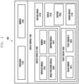
- Fig. 1 is a block diagram illustrating an electronic device 101 in a network environment 100 according to various embodiments.
- the electronic device 101 in the network environment 100 may communicate with an electronic device 102 via a first network 198 (e.g., a short-range wireless communication network), or at least one of an electronic device 104 or a server 108 via a second network 199 (e.g., a long-range wireless communication network).
- a first network 198 e.g., a short-range wireless communication network
- a second network 199 e.g., a long-range wireless communication network
- the electronic device 101 may communicate with the electronic device 104 via the server 108.
- the electronic device 101 may include a processor 120, memory 130, an input module 150, a sound output module 155, a display module 160, an audio module 170, a sensor module 176, an interface 177, a connecting terminal 178, a haptic module 179, a camera module 180, a power management module 188, a battery 189, a communication module 190, a subscriber identification module(SIM) 196, or an antenna module 197.
- at least one of the components e.g., the connecting terminal 178) may be omitted from the electronic device 101, or one or more other components may be added in the electronic device 101.
- some of the components e.g., the sensor module 176, the camera module 180, or the antenna module 197) may be implemented as a single component (e.g., the display module 160).
- the processor 120 may execute, for example, software (e.g., a program 140) to control at least one other component (e.g., a hardware or software component) of the electronic device 101 coupled with the processor 120, and may perform various data processing or computation. According to one embodiment, as at least part of the data processing or computation, the processor 120 may store a command or data received from another component (e.g., the sensor module 176 or the communication module 190) in volatile memory 132, process the command or the data stored in the volatile memory 132, and store resulting data in non-volatile memory 134.
- software e.g., a program 140
- the processor 120 may store a command or data received from another component (e.g., the sensor module 176 or the communication module 190) in volatile memory 132, process the command or the data stored in the volatile memory 132, and store resulting data in non-volatile memory 134.
- the processor 120 may include a main processor 121 (e.g., a central processing unit (CPU) or an application processor (AP)), or an auxiliary processor 123 (e.g., a graphics processing unit (GPU), a neural processing unit (NPU), an image signal processor (ISP), a sensor hub processor, or a communication processor (CP)) that is operable independently from, or in conjunction with, the main processor 121.
- a main processor 121 e.g., a central processing unit (CPU) or an application processor (AP)
- auxiliary processor 123 e.g., a graphics processing unit (GPU), a neural processing unit (NPU), an image signal processor (ISP), a sensor hub processor, or a communication processor (CP)
- the main processor 121 may be adapted to consume less power than the main processor 121, or to be specific to a specified function.
- the auxiliary processor 123 may be implemented as separate from, or as part of the main processor 121.
- the auxiliary processor 123 may control at least some of functions or states related to at least one component (e.g., the display module 160, the sensor module 176, or the communication module 190) among the components of the electronic device 101, instead of the main processor 121 while the main processor 121 is in an inactive (e.g., sleep) state, or together with the main processor 121 while the main processor 121 is in an active state (e.g., executing an application).
- the auxiliary processor 123 e.g., an image signal processor or a communication processor
- the auxiliary processor 123 may include a hardware structure specified for artificial intelligence model processing.
- An artificial intelligence model may be generated by machine learning. Such learning may be performed, e.g., by the electronic device 101 where the artificial intelligence is performed or via a separate server (e.g., the server 108). Learning algorithms may include, but are not limited to, e.g., supervised learning, unsupervised learning, semi-supervised learning, or reinforcement learning.
- the artificial intelligence model may include a plurality of artificial neural network layers.
- an element e.g., a first element
- the element may be coupled with the other element directly (e.g., wiredly), wirelessly, or via a third element.
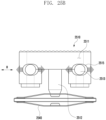
- the electronic device 101 may be configured to be folded or unfolded (e.g., an electronic device 200 of FIGS. 2A to 2D ), and the display module 160 may include a flexible display configured to be folded or unfolded.
- the first housing 210 and the second housing 220 are disposed on either side of the folding axis F, to give the electronic device 200 an overall symmetrical shape with respect to the folding axis F.
- the first housing 210 and the second housing 220 can be folded to match each other.
- the first housing 210 and the second housing 220 may have a different angle or distance therebetween according to whether the electronic device 200 is in a first state (e.g., unfolded state), a second state (e.g., folded state), or a third state (e.g., intermediate state).
- the electronic device 200 may sense whether it is in a first state (e.g., unfolded state), a second state (e.g., folded state), or a third state (e.g., intermediate state) using a sensor module (e.g., the sensor module 176 of FIG. 1 ).
- the electronic device 200 may sense an angle between the first housing 210 and the second housing 220 using the sensor module (e.g., the sensor module 176 of FIG. 1 ).
- the first housing 210 may be connected to at least one hinge device in the first state (e.g., unfolded state) of the electronic device 200.
- the first housing 210 may include a first surface 211 disposed to face the front surface of the electronic device 200, a second surface 212 facing in a direction opposite to that of the first surface 211, and/or a first lateral member 213 enclosing at least a portion of a first space 2101 between the first surface 211 and the second surface 212.
- the second housing 220 may be connected to at least one hinge device in the first state (e.g., unfolded state) of the electronic device 200.
- the second housing 220 may include a third surface 221 disposed to face the front surface of the electronic device 200, a fourth surface 222 facing in a direction opposite to that of the third surface 221, and/or a second lateral member 223 enclosing at least a portion of a second space 2201 between the third surface 221 and the fourth surface 222.
- the first surface 211 may face in substantially the same direction as that of the third surface 221 in the first state (e.g., unfolded state), and at least partially face the third surface 221 in the second state (e.g., folded state).
- the electronic device 200 may include a recess 201 formed to receive the first display 230 through structural coupling of the first housing 210 and the second housing 220.
- the recess 201 may have substantially the same size as that of the first display 230.
- the second housing 220 may be coupled to a second lateral member 223 when the first display 230 is viewed from above.
- the second housing 220 may include a second protection frame 223a disposed to overlap an edge of the first display 230 to cover the edge of the first display 230 so that it is invisible from the outside.
- the second protection frame 223a may be formed integrally with the second lateral member 223.
- the first protection frame 213a and the second protection frame 223a may be omitted.
- the hinge housing 290 (e.g., hinge cover) may be disposed between the first housing 210 and the second housing 220.
- the hinge housing 290 may be disposed to cover a portion (e.g., at least one hinge module) of at least one hinge device.
- the hinge housing 290 may be covered by a portion of the first housing 210 and the second housing 220 or may be exposed to the outside according to the first state (e.g., unfolded state), the second state (e.g., folded state), or the third state (e.g., intermediate state) of the electronic device 200.
- the first state e.g., unfolded state
- the second state e.g., folded state
- the third state e.g., intermediate state
- the hinge housing 290 may be covered by the first housing 210 and the second housing 220 to be disposed to be substantially invisible from the outside.
- At least a portion of the hinge housing 290 may be disposed to be visible from the outside between the first housing 210 and the second housing 220.
- the hinge housing 290 may be disposed between the first housing 210 and the second housing 220 so as to be at least partially visible from the outside of the electronic device 200.
- an area of the hinge housing 290 exposed to the outside may be smaller than that in a state in which the first housing 210 and the second housing 220 are fully folded.
- the hinge housing 290 may include a curved surface.
- the first housing 210 and the second housing 220 may form an angle of about 180 degrees, and a first area 230a, a second area 230b, and a folding area 230c of the first display 230 may form substantially the same plane.
- the first area 230a, the second area 230b, and the folding area 230c of the first display 230 may be disposed to face substantially the same direction (e.g., z-axis direction).
- the first housing 210 may rotate to an angle of about 360 degrees with respect to the second housing 220 to be folded in the opposite direction so that the second surface 212 and the fourth surface 222 face each other (e.g., out folding manner).
- the first surface 211 of the first housing 210 and the third surface 221 of the second housing 220 may be disposed to face each other.
- the first area 230a and the second area 230b of the first display 230 may form a narrow angle (e.g., the range of 0 degrees to about 10 degrees) with each other through the folding area 230c and be disposed to face each other.
- at least a portion of the folding area 230c may be transformed into a curved shape with a predetermined curvature.
- the first housing 210 and the second housing 220 may be disposed at a certain angle to each other.
- the first area 230a and the second area 230b of the first display 230 may form an angle greater than that in the second state (e.g., folded state) and smaller than that in the first state (e.g., unfolded state), and a curvature of the folding area 230c may be smaller than that in the second state (e.g., folded state) and greater than that in the first state (e.g., unfolded state).
- first housing 210 and the second housing 220 may form an angle that may stop at a designated folding angle between the second state (e.g., folded state) and the third state (e.g., intermediate state) through at least one hinge device (e.g., free stop function).
- first housing 210 and the second housing 220 may be continuously operated while being pressed in an unfolding or folding direction based on a designated inflection angle through at least one hinge device.
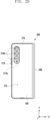
- the electronic device 200 includes a display 230 and 235, an input device 215, sound output devices 227 and 228, sensor modules 217a, 217b, and 226, camera modules 216a, 216b, and 225, a key input device 219, an indicator (not illustrated), or a connector port 229 disposed in the first housing 210 and/or the second housing 220.
- the key input device 219 includes a side key, and may optionally include other keys, such as a power button.
- the electronic device 200 may omit at least one of the components or additionally include at least one other component.
- the at least one display 230 and 235 may include a first display 230 (e.g., flexible display) from the first surface 211 of the first housing 210 to be disposed to be supported by the third surface 221 of the second housing 220 through at least one hinge device, and a second display 235 disposed to be at least partially visible from the outside through the fourth surface 222 in an inner space of the second housing 220.
- a first display 230 e.g., flexible display
- the second display 235 may be disposed to be visible from the outside through the second surface 212 in an inner space of the first housing 210.
- the first display 230 may be mainly used in the first state (e.g., unfolded state) of the electronic device 200.
- the second display 235 may be used even in the first state (e.g., unfolded state) of the electronic device 200.
- the second display 235 may be mainly used in the second state (e.g., folded state) of the electronic device 200.
- the first display 230 may be used even in the second state (e.g., folded state) of the electronic device 200.
- the electronic device 200 may control to use the first display 230 and/or the second display 235 based on a folding angle of the first housing 210 and the second housing 220.
- the first display 230 may be disposed in a receiving space formed by a pair of housings 210 and 220.
- the first display 200 may be disposed in the recess 201 formed by a pair of housings 210 and 220, and be disposed to occupy substantially most of the front surface of the electronic device 200 in the first state (e.g., unfolded state).
- the first display 230 may include a flexible display having at least a partial area that may be transformed into a flat surface or a curved surface.
- the first display 230 may include a first area 230a facing the first housing 210 and a second area 230b facing the second housing 220. According to an embodiment, the first display 230 may include a folding area 230c including a portion of the first area 230a and a portion of the second area 230b based on the folding axis F.
- At least a portion of the folding area 230c may include an area corresponding to at least one hinge device.
- area division of the first display 230 is only exemplary physical division by a pair of housings 210 and 220 and at least one hinge device, and the first display 230 may be displayed as a substantially seamless and single full screen through a pair of housings 210 and 220 and at least one hinge device.
- the first area 230a and the second area 230b may have an overall symmetrical shape or a partially asymmetrical shape based on the folding area 230c.
- the electronic device 200 may include a first rear cover 240 disposed at the second surface 212 of the first housing 210, and a second rear cover 250 disposed at the fourth surface 222 of the second housing 220.
- at least a portion of the first rear cover 240 may be formed integrally with the first lateral member 213.
- at least a portion of the second rear cover 250 may be formed integrally with the second lateral member 223.
- At least one of the first rear cover 240 and the second rear cover 250 may be formed with a substantially transparent plate (e.g., a glass plate or a polymer plate including various coating layers) or an opaque plate.
- the first rear cover 240 may be formed by an opaque plate, for example, coated or colored glass, ceramic, polymer, metal (e.g., aluminum, stainless steel (STS), or magnesium), or a combination of at least two of the above materials.
- the input device 215 may include a microphone.
- the input device 215 may include a plurality of microphones disposed to detect a direction of sound.
- the DDIC 430 may receive image data or image information including an image control signal corresponding to a command for controlling the image data from other components of the electronic device (e.g., the electronic device 101 of FIG. 1 , the electronic device 200 of FIGS. 2 and 3 ) through the interface module 431.
- the vibration structure driving IC 550 may drive or control the plurality of vibration structures 530 based on the control of the processor 120.
- the sensor driving IC 560 may drive or control the plurality of sensors 540 based on the control of the processor 120.
- the memory 130 may include instructions for operating the processor 120, the vibration structure driving IC 550, and the sensor driving IC 560.
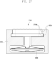
- FIG. 6 is a diagram illustrating an electronic device 600 including a housing 610 and a side key 620.
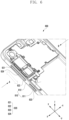
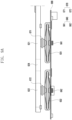
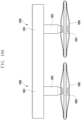
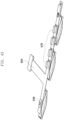
- FIG. 7 is a diagram illustrating the side key 620 and a plurality of vibration structures 630.
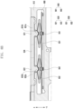
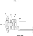
- FIG. 8A is a cross-sectional view illustrating the side key 620, and the plurality of vibration structures 630 within the housing 610.
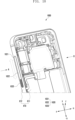
- an electronic device 600 (e.g., the electronic device 101 of FIG. 1 , the electronic device 200 of FIG. 2A , the electronic device 300 of FIG. 3A , the electronic device 400 of FIG. 4 , the electronic device 500 of FIG. 5 ) includes a housing 610 including a bottom surface 611 and a side surface 612 formed to enclose (e.g., surround) the bottom surface 611, and a side key 620 (e.g., the side key 520 of FIG. 5 , a plurality of side buttons) that is configured to allow a user key input.
- a hole is formed in the side surface 612 (e.g., the side bezel structure 318 of FIG.
- the housing 610 e.g., the housings 210 and 220 of FIG. 2A , the housing 310 of FIG. 3A ), so that an upper surface (e.g., pressing surface, touch surface, surface) of the side key 620 is exposed to the outside of the electronic device through the hole in the side surface 612 of the housing 610.
- an upper surface e.g., pressing surface, touch surface, surface
- the side key 620 includes a plurality of key structures 621, 622, and 623 (e.g., the plurality of key structures 521, 522, and 523 of FIG. 5 ) configured to allow a user key input.
- FIG. 7 illustrates the first key structure 621, the second key structure 622, and the third key structure 623.
- the first key structure 621 is for a user's first key input
- the second key structure 622 is for a user's second key input
- the third key structure 623 is for a user's third key input.
- the first key structure 621 and the second key structure 622 are connected through a connection part 624 to be disposed as one side key (e.g., side button).
- the third key structure 623 is disposed separately to the connected first and second key structures.
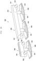
- the lower end portion of the second part 621b of the first key structure 621 is inserted (e.g., received) into the first groove 63 1a formed in the first vibration structure 631; in this way, the first key structure 621 is fixed over the first vibration structure 631.
- a similar configuration can be applied to the second and third key structures, to fix them over the second and third vibration structures, respectively.
- a lower end of the second part 622b of the second key structure 622 can be inserted (e.g., received) into a second groove 632a formed in the second vibration structure 632.
- a lower end of the second part 623b of the third key structure 623 can be inserted (e.g., received) into a third groove 633a formed in the third vibration structure 633.
- a vibration is applied to the side key 620 (e.g., a plurality of side buttons) by the plurality of vibration structures 630; thus, the side key 620 (e.g., a plurality of side buttons) may provide a haptic function.
- the electronic device 600 may include a plurality of sensors 640 (e.g., the plurality of sensors 540 of FIG. 5 ) for sensing a user key input or a user interaction with the side key 520, e.g., a pressing (or touch) of the side key 620.
- a plurality of sensors 640 e.g., the plurality of sensors 540 of FIG. 5
- the side key 520 e.g., a pressing (or touch) of the side key 620.
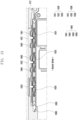
- the plurality of sensors 640 and the plurality of vibration structures 630 may be disposed on a printed circuit board 680.
- the plurality of sensors 640 may include a first sensor 641 (e.g., pressure sensor, ultrasonic sensor, touch sensor) for sensing pressing of the first key structure 621, and a second sensor 642 (e.g., pressure sensor, ultrasonic sensor, touch sensor) for sensing pressing of the second key structure 622.
- a third sensor e.g., pressure sensor, ultrasonic sensor, touch sensor
- the first sensor 641 e.g., pressure sensor, ultrasonic sensor, or touch sensor
- the second sensor 642 (e.g., pressure sensor, ultrasonic sensor, or touch sensor) may sense pressing or a touch of the second key structure 622.
- the third sensor (not illustrated) (e.g., pressure sensor, ultrasonic sensor, touch sensor) may sense pressing or a touch of the third key structure 623.
- the electronic device 600 may include a vibration structure driving IC (e.g., the vibration structure driving IC 550 of FIG. 5 ) for operating the plurality of vibration structures 630.
- a vibration structure driving IC e.g., the vibration structure driving IC 550 of FIG. 5
- the electronic device 600 may include a sensor driving IC (e.g., the sensor driving IC 560 of FIG. 5 ) for operating the plurality of sensors 540.
- a sensor driving IC e.g., the sensor driving IC 560 of FIG. 5
- the electronic device 600 may include a processor (e.g., the processor 120 of FIG. 1 , the processor 120 of FIG. 5 ) for controlling operations of the vibration structure driving IC 550 and the sensor driving IC 560.
- a processor e.g., the processor 120 of FIG. 1 , the processor 120 of FIG. 5
- the vibration structure driving IC 550 the vibration structure driving IC 550
- the sensor driving IC 560 the vibration structure driving IC 550 and the sensor driving IC 560.
- the electronic device 600 may include a memory (e.g., the memory 130 of FIG. 1 , the memory 130 of FIG. 5 ) operatively connected to the processor 120.
- the memory 130 may include instructions for operating the processor 120, the vibration structure driving IC 550, and the sensor driving IC 560.
- the vibration structure driving IC 550 may drive the plurality of vibration structures 630 based on the control of the processor 120.
- the sensor driving IC 560 may drive the plurality of sensors 640 based on the control of the processor 120.
- the memory 130 may include instructions for operating the processor 120, the vibration structure driving IC 550, and the sensor driving IC 560.
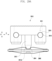
- FIG. 8B is a cross-sectional view illustrating a side surface, a side key, and a plurality of vibration structures of the housing.
- FIG. 8B When describing the plurality of vibration structures 630 of the side key 620 of FIG. 8B , a detailed description of the same (or similar) constitution as that of FIGS. 7 and 8A may be omitted.
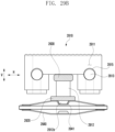
- FIG. 8C is a cross-sectional view illustrating a side surface, a side key, and a vibration structure of the housing.
- a detailed description of the same (or similar) constitution as that of FIG. 8A or 8B may be omitted.
- an electronic device 600 may include a housing 610 including a bottom surface 611 and a side surface 612 formed to enclose (e.g., surround) the bottom surface 611, and a side key 620 for a user key input.
- a hole may be formed at the side surface 612 (e.g., the side bezel structure 318 of FIG. 3A ) of the housing 610, and an upper surface (e.g., pressing surface, touch surface, surface) of the side key 620 may be exposed to the outside through the hole of the side surface 612 of the housing 610.
- first key structure 621 and the second key structure 622 of FIG. 8A or 8B may be integrated to form one complex key structure 650 (e.g., broad key structure).
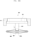
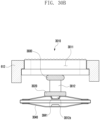
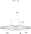
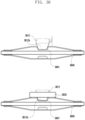
- a bottom surface of a groove 3941 formed in a vibration structure 3940 may be formed in a concave shape (e.g., hemispherical shape).
- the second part 3912 of the key structure may be inserted into the groove 3941 of the vibration structure 3940; thus, the second part 3912 of the key structure and the vibration structure 3940 may be disposed to contact each other.
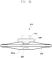
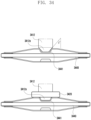
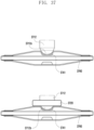
- a convex-shaped protrusion 4041 may be formed at an upper surface of a vibration structure 4040.
- the protrusion 4041 of the vibrating structure 4040 is inserted into the groove 4012a formed at a lower end portion of the second part 4012 of the key structure; thus, the second part 4012 of the key structure and the vibrating structure 4040 may be disposed to contact each other.
- a width of the second part 4012 of the key structure may be formed to be wider than that of the protrusion 4041 formed in the vibration structure 4040.
- the width of the second part 4012 of the key structure is formed to be wider than that of the protrusion 4041 formed in the vibration structure 4040; thus, at least a portion of a lower surface of the second part 4012 of the key structure may be disposed to contact an upper surface of the vibration structure 4040.
- the width of the second part 4012 of the key structure is formed to be wider than that of the protrusion 4041 formed in the vibration structure 4040; thus, an area of a contact point between the key structure and the vibration structure 4040 is expanded, i.e., increased. In this way, a vibration generated in the vibration structure 4040 can be more effectively transferred to the key structure by the contact point expansion member 3230 (e.g., contact point expansion structure, contact point expansion ring).
- the contact point expansion member 3230 e.g., contact point expansion structure, contact point expansion ring
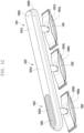
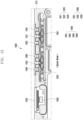
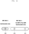
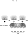
- FIGS. 41 and 42 are diagrams illustrating sensing a user's swipe key input using a side key.
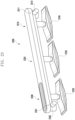
- FIG. 43 is a diagram illustrating a plurality of sensors and vibration structures disposed on a printed circuit board.
- the electronic device of the disclosure may sense an input of a first key 4110, a second key 4120, and a third key 4130 using a plurality of key structures (e.g., three key structures) included in a side key 4100.
- a plurality of key structures e.g., three key structures
- the first key 4110 may be used as a volume up key.
- the second key 4120 may be used as a volume down key.
- the third key 4130 may be used as a home key (or power on-off key).
- the user's swipe key input (e.g., sliding key input) may be sensed using the first key 4110 and the second key 4120.
- the user's swipe key input moving from the second key 4120 to the first key 4110 may be sensed using the plurality of sensors 4171, 4172, 4173, 4174, and 4175.
- a swipe key input e.g., sliding key input
- the electronic device (e.g., the electronic device 101 of FIG. 1 , the electronic device 200 of FIG. 2A , the electronic device 300 of FIG. 3A , the electronic device 400 of FIG. 4 , the electronic device 500 of FIG. 5 , the electronic device 600 of FIG. 6 , and the electronic device 1000 of FIG. 10 ) according to an embodiment of the disclosure may independently provide a haptic function with a plurality of side keys disposed at one side surface (or both side surfaces) of the housing (e.g., the housing 610 of FIG. 6 , the housing 610 of FIG. 10 ).
- the electronic device (e.g., the electronic device 101 of FIG. 1 , the electronic device 200 of FIG. 2A , the electronic device 300 of FIG. 3A , the electronic device 400 of FIG. 4 , the electronic device 500 of FIG. 5 , the electronic device 600 of FIG. 6 , and the electronic device 1000 of FIG. 10 ) according to an embodiment of the disclosure may prevent a plurality of side keys from being significantly deviated from original positions thereof when pressed or touched.
- the electronic device (e.g., the electronic device 101 of FIG. 1 , the electronic device 200 of FIG. 2A , the electronic device 300 of FIG. 3A , the electronic device 400 of FIG. 4 , the electronic device 500 of FIG. 5 , the electronic device 600 of FIG. 6 , and the electronic device 1000 of FIG. 10 ) according to an embodiment of the disclosure may provide a haptic function with a plurality of side keys disposed at one side surface (or both side surfaces) of the housing (e.g., the housing 610 of FIG. 6 , the housing 610 of FIG. 10 ) and perform a function according to the user's swipe key input (e.g., sliding key input).
- a haptic function with a plurality of side keys disposed at one side surface (or both side surfaces) of the housing (e.g., the housing 610 of FIG. 6 , the housing 610 of FIG. 10 ) and perform a function according to the user's swipe key input (e.g., sliding key input).
- the electronic device (e.g., the electronic device 101 of FIG. 1 , the electronic device 200 of FIG. 2A , the electronic device 300 of FIG. 3A , the electronic device 400 of FIG. 4 , the electronic device 500 of FIG. 5 , the electronic device 600 of FIG. 6 , and the electronic device 1000 of FIG. 10 ) according to an embodiment of the disclosure may provide a haptic function with a plurality of side keys disposed at one side surface (or both side surfaces) of the housing (e.g., the housing 610 of FIG. 6 , the housing 610 of FIG. 10 ) and perform a function according to the user's scroll key input.
- a haptic function with a plurality of side keys disposed at one side surface (or both side surfaces) of the housing (e.g., the housing 610 of FIG. 6 , the housing 610 of FIG. 10 ) and perform a function according to the user's scroll key input.
- the electronic device (e.g., the electronic device 101 of FIG. 1 , the electronic device 200 of FIG. 2A , the electronic device 300 of FIG. 3A , the electronic device 400 of FIG. 4 , the electronic device 500 of FIG. 5 , the electronic device 600 of FIG. 6 , and the electronic device 1000 of FIG. 10 ) according to an embodiment of the disclosure may provide a haptic function with a plurality of side keys disposed at one side surface (or both side surfaces) of the housing (e.g., the housing 610 of FIG. 6 , the housing 610 of FIG. 10 ) and perform functions by pressing the plurality of side keys disposed at one side surface (or both side surfaces) of the housing.
- a haptic function with a plurality of side keys disposed at one side surface (or both side surfaces) of the housing (e.g., the housing 610 of FIG. 6 , the housing 610 of FIG. 10 ) and perform functions by pressing the plurality of side keys disposed at one side surface (or both side surfaces) of
- the electronic device (e.g., the electronic device 101 of FIG. 1 , the electronic device 200 of FIG. 2A , the electronic device 300 of FIG. 3A , the electronic device 400 of FIG. 4 , the electronic device 500 of FIG. 5 , the electronic device 600 of FIG. 6 , and the electronic device 1000 of FIG. 10 ) according to an embodiment of the disclosure may sense the user's touch on a plurality of side keys, thereby reducing a thickness of the plurality of side keys.
- the side key 620 illustrated in FIGS. 6 and 7 may be applied to the electronic device 200 (e.g., foldable electronic device) of FIGS. 2A to 2D or the electronic device 300 (e.g., flat panel type electronic device) of FIGS. 3A and 3B .
- the side key 620 illustrated in FIGS. 6 and 7 may be applied to a foldable electronic device that may be in-folded or out-folded in a horizontal direction (e.g., x-axis direction) or a foldable electronic device that may be in-folded or out-folded in a vertical direction (e.g., y-axis direction).
- the side key 620 illustrated in FIGS. 6 and 7 may be applied to an electronic device (e.g., slidable electronic device) disposed to slide in a first direction (e.g., slide in the x-axis direction) or to slide in a second direction (e.g., slide in the y-axis direction) to change a size of a screen.
- an electronic device e.g., slidable electronic device
- a first direction e.g., slide in the x-axis direction
- a second direction e.g., slide in the y-axis direction
- the side key 1020 illustrated in FIGS. 10 and 11 may be applied to the electronic device 200 (e.g., foldable electronic device) of FIGS. 2A to 2D or the electronic device 300 (e.g., flat panel type electronic device) of FIGS. 3A and 3B .
- the side key 1020 illustrated in FIGS. 10 and 11 may be applied to a foldable electronic device that may be in-folded or out-folded in the horizontal direction (e.g., x-axis direction) or a foldable electronic device that may be in-folded or out-folded in the vertical direction (e.g., y-axis direction).
Landscapes
- Engineering & Computer Science (AREA)
- Theoretical Computer Science (AREA)
- General Engineering & Computer Science (AREA)
- Human Computer Interaction (AREA)
- Physics & Mathematics (AREA)
- General Physics & Mathematics (AREA)
- Computer Hardware Design (AREA)
- Signal Processing (AREA)
- Telephone Function (AREA)
- Telephone Set Structure (AREA)
Applications Claiming Priority (3)
| Application Number | Priority Date | Filing Date | Title |
|---|---|---|---|
| KR20230164665 | 2023-11-23 | ||
| KR1020240014230A KR20250077312A (ko) | 2023-11-23 | 2024-01-30 | 전자 장치 |
| PCT/KR2024/018554 WO2025110770A1 (ko) | 2023-11-23 | 2024-11-21 | 사이드 키를 포함하는 전자 장치 |
Publications (1)
| Publication Number | Publication Date |
|---|---|
| EP4583136A1 true EP4583136A1 (de) | 2025-07-09 |
Family
ID=95474786
Family Applications (1)
| Application Number | Title | Priority Date | Filing Date |
|---|---|---|---|
| EP24866577.0A Pending EP4583136A1 (de) | 2023-11-23 | 2024-11-21 | Elektronische vorrichtung mit seitenschlüssel |
Country Status (2)
| Country | Link |
|---|---|
| EP (1) | EP4583136A1 (de) |
| WO (1) | WO2025110770A1 (de) |
Family Cites Families (5)
| Publication number | Priority date | Publication date | Assignee | Title |
|---|---|---|---|---|
| JPH05250955A (ja) * | 1991-09-30 | 1993-09-28 | Matsushita Electric Works Ltd | 操作スイッチ |
| JPH0935569A (ja) * | 1995-07-18 | 1997-02-07 | Yazaki Corp | スイッチ装置 |
| KR100672449B1 (ko) * | 2004-07-22 | 2007-01-24 | 엘지전자 주식회사 | 이동통신 단말기의 사이드 버튼 장치 |
| JP2013218820A (ja) * | 2012-04-05 | 2013-10-24 | Tokai Rika Co Ltd | スイッチ装置 |
| KR102880120B1 (ko) * | 2020-10-16 | 2025-11-04 | 삼성전자주식회사 | 사이드 키를 포함하는 전자 장치 |
-
2024
- 2024-11-21 EP EP24866577.0A patent/EP4583136A1/de active Pending
- 2024-11-21 WO PCT/KR2024/018554 patent/WO2025110770A1/ko active Pending
Also Published As
| Publication number | Publication date |
|---|---|
| WO2025110770A1 (ko) | 2025-05-30 |
Similar Documents
| Publication | Publication Date | Title |
|---|---|---|
| US12411645B2 (en) | Foldable electronic device for controlling screen rotation, and operating method therefor | |
| US20220113764A1 (en) | Electronic device including friction reducing structure | |
| US11853546B2 (en) | Electronic device for controlling input mode according to folding angle, and method therefor | |
| US12321199B2 (en) | Use method according to folding state of display, and electronic apparatus using same | |
| US12079044B2 (en) | Electronic device having flexible display and method for providing control panel according to mode change thereof | |
| US20250021288A1 (en) | Electronic device including flexible display and method for controlling same | |
| US11984054B2 (en) | Electronic device having flexible display | |
| US20230122806A1 (en) | Electronic device for moving position of visual object located in folding area and method for controlling same | |
| EP4583136A1 (de) | Elektronische vorrichtung mit seitenschlüssel | |
| US20220374054A1 (en) | Foldable electronic device including a plurality of fingerprint sensors | |
| EP4231129A1 (de) | Verfahren zum betrieb einer flexiblen anzeige und elektronische vorrichtung | |
| EP4177717B1 (de) | Faltbare elektronische vorrichtung zur steuerung der bildschirmrotation und betriebsverfahren dafür | |
| KR20250077312A (ko) | 전자 장치 | |
| EP4642017A1 (de) | Elektronische vorrichtung mit flexibler anzeige und verfahren zur identifizierung eines gefalteten oder nicht gefalteten zustands | |
| EP4664715A1 (de) | Elektronische vorrichtung, andockvorrichtung und verfahren zum betrieb einer elektronischen vorrichtung und andockvorrichtung | |
| US12494812B2 (en) | Electronic device including magnets | |
| EP4636536A1 (de) | Faltbare elektronische vorrichtung und winkelerkennungsverfahren damit | |
| US12190763B2 (en) | Electronic device including flexible display and operation method thereof | |
| US20230254402A1 (en) | Electronic device and method for displaying screen thereof | |
| EP4664235A1 (de) | Elektronische vorrichtung mit dickenkompensationselement | |
| US20230105902A1 (en) | Electronic device including magnets | |
| EP4509948A1 (de) | Mehrfach faltbare elektronische vorrichtung und benachrichtigungsbereitstellungsverfahren einer mehrfach faltbaren elektronischen vorrichtung | |
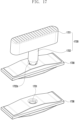
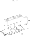
| EP4425910A1 (de) | Anzeigevorrichtung und ständermodul | |
| EP4557061A1 (de) | Elektronische vorrichtung mit berührungsfeld | |
| KR20240118627A (ko) | 플렉서블 디스플레이를 포함하는 전자 장치 및 접힘 상태 또는 펼침 상태를 확인하는 방법 |
Legal Events
| Date | Code | Title | Description |
|---|---|---|---|
| STAA | Information on the status of an ep patent application or granted ep patent |
Free format text: STATUS: UNKNOWN |
|
| STAA | Information on the status of an ep patent application or granted ep patent |
Free format text: STATUS: THE INTERNATIONAL PUBLICATION HAS BEEN MADE |
|
| PUAI | Public reference made under article 153(3) epc to a published international application that has entered the european phase |
Free format text: ORIGINAL CODE: 0009012 |
|
| STAA | Information on the status of an ep patent application or granted ep patent |
Free format text: STATUS: REQUEST FOR EXAMINATION WAS MADE |
|
| 17P | Request for examination filed |
Effective date: 20250325 |
|
| AK | Designated contracting states |
Kind code of ref document: A1 Designated state(s): AL AT BE BG CH CY CZ DE DK EE ES FI FR GB GR HR HU IE IS IT LI LT LU LV MC ME MK MT NL NO PL PT RO RS SE SI SK SM TR |