EP4583129A1 - Pulverkern, legierungspartikel, elektronisches element, elektronische vorrichtung, elektromotor und dynamo - Google Patents
Pulverkern, legierungspartikel, elektronisches element, elektronische vorrichtung, elektromotor und dynamo Download PDFInfo
- Publication number
- EP4583129A1 EP4583129A1 EP23859993.0A EP23859993A EP4583129A1 EP 4583129 A1 EP4583129 A1 EP 4583129A1 EP 23859993 A EP23859993 A EP 23859993A EP 4583129 A1 EP4583129 A1 EP 4583129A1
- Authority
- EP
- European Patent Office
- Prior art keywords
- sio
- core
- alloy
- dust core
- mass
- Prior art date
- Legal status (The legal status is an assumption and is not a legal conclusion. Google has not performed a legal analysis and makes no representation as to the accuracy of the status listed.)
- Pending
Links
Images




Classifications
-
- H—ELECTRICITY
- H01—ELECTRIC ELEMENTS
- H01F—MAGNETS; INDUCTANCES; TRANSFORMERS; SELECTION OF MATERIALS FOR THEIR MAGNETIC PROPERTIES
- H01F1/00—Magnets or magnetic bodies characterised by the magnetic materials therefor; Selection of materials for their magnetic properties
- H01F1/01—Magnets or magnetic bodies characterised by the magnetic materials therefor; Selection of materials for their magnetic properties of inorganic materials
- H01F1/03—Magnets or magnetic bodies characterised by the magnetic materials therefor; Selection of materials for their magnetic properties of inorganic materials characterised by their coercivity
- H01F1/032—Magnets or magnetic bodies characterised by the magnetic materials therefor; Selection of materials for their magnetic properties of inorganic materials characterised by their coercivity of hard-magnetic materials
- H01F1/04—Magnets or magnetic bodies characterised by the magnetic materials therefor; Selection of materials for their magnetic properties of inorganic materials characterised by their coercivity of hard-magnetic materials metals or alloys
- H01F1/06—Magnets or magnetic bodies characterised by the magnetic materials therefor; Selection of materials for their magnetic properties of inorganic materials characterised by their coercivity of hard-magnetic materials metals or alloys in the form of particles, e.g. powder
- H01F1/08—Magnets or magnetic bodies characterised by the magnetic materials therefor; Selection of materials for their magnetic properties of inorganic materials characterised by their coercivity of hard-magnetic materials metals or alloys in the form of particles, e.g. powder pressed, sintered, or bound together
- H01F1/086—Magnets or magnetic bodies characterised by the magnetic materials therefor; Selection of materials for their magnetic properties of inorganic materials characterised by their coercivity of hard-magnetic materials metals or alloys in the form of particles, e.g. powder pressed, sintered, or bound together sintered
-
- H—ELECTRICITY
- H01—ELECTRIC ELEMENTS
- H01F—MAGNETS; INDUCTANCES; TRANSFORMERS; SELECTION OF MATERIALS FOR THEIR MAGNETIC PROPERTIES
- H01F1/00—Magnets or magnetic bodies characterised by the magnetic materials therefor; Selection of materials for their magnetic properties
- H01F1/01—Magnets or magnetic bodies characterised by the magnetic materials therefor; Selection of materials for their magnetic properties of inorganic materials
- H01F1/03—Magnets or magnetic bodies characterised by the magnetic materials therefor; Selection of materials for their magnetic properties of inorganic materials characterised by their coercivity
- H01F1/12—Magnets or magnetic bodies characterised by the magnetic materials therefor; Selection of materials for their magnetic properties of inorganic materials characterised by their coercivity of soft-magnetic materials
- H01F1/14—Magnets or magnetic bodies characterised by the magnetic materials therefor; Selection of materials for their magnetic properties of inorganic materials characterised by their coercivity of soft-magnetic materials metals or alloys
- H01F1/20—Magnets or magnetic bodies characterised by the magnetic materials therefor; Selection of materials for their magnetic properties of inorganic materials characterised by their coercivity of soft-magnetic materials metals or alloys in the form of particles, e.g. powder
- H01F1/22—Magnets or magnetic bodies characterised by the magnetic materials therefor; Selection of materials for their magnetic properties of inorganic materials characterised by their coercivity of soft-magnetic materials metals or alloys in the form of particles, e.g. powder pressed, sintered, or bound together
- H01F1/24—Magnets or magnetic bodies characterised by the magnetic materials therefor; Selection of materials for their magnetic properties of inorganic materials characterised by their coercivity of soft-magnetic materials metals or alloys in the form of particles, e.g. powder pressed, sintered, or bound together the particles being insulated
-
- B—PERFORMING OPERATIONS; TRANSPORTING
- B22—CASTING; POWDER METALLURGY
- B22F—WORKING METALLIC POWDER; MANUFACTURE OF ARTICLES FROM METALLIC POWDER; MAKING METALLIC POWDER; APPARATUS OR DEVICES SPECIALLY ADAPTED FOR METALLIC POWDER
- B22F1/00—Metallic powder; Treatment of metallic powder, e.g. to facilitate working or to improve properties
- B22F1/17—Metallic particles coated with metal
-
- B—PERFORMING OPERATIONS; TRANSPORTING
- B22—CASTING; POWDER METALLURGY
- B22F—WORKING METALLIC POWDER; MANUFACTURE OF ARTICLES FROM METALLIC POWDER; MAKING METALLIC POWDER; APPARATUS OR DEVICES SPECIALLY ADAPTED FOR METALLIC POWDER
- B22F3/00—Manufacture of workpieces or articles from metallic powder characterised by the manner of compacting or sintering; Apparatus specially adapted therefor ; Presses and furnaces
- B22F3/24—After-treatment of workpieces or articles
-
- B—PERFORMING OPERATIONS; TRANSPORTING
- B22—CASTING; POWDER METALLURGY
- B22F—WORKING METALLIC POWDER; MANUFACTURE OF ARTICLES FROM METALLIC POWDER; MAKING METALLIC POWDER; APPARATUS OR DEVICES SPECIALLY ADAPTED FOR METALLIC POWDER
- B22F5/00—Manufacture of workpieces or articles from metallic powder characterised by the special shape of the product
- B22F5/10—Manufacture of workpieces or articles from metallic powder characterised by the special shape of the product of articles with cavities or holes, not otherwise provided for in the preceding subgroups
- B22F5/106—Tube or ring forms
-
- C—CHEMISTRY; METALLURGY
- C21—METALLURGY OF IRON
- C21D—MODIFYING THE PHYSICAL STRUCTURE OF FERROUS METALS; GENERAL DEVICES FOR HEAT TREATMENT OF FERROUS OR NON-FERROUS METALS OR ALLOYS; MAKING METAL MALLEABLE, e.g. BY DECARBURISATION OR TEMPERING
- C21D6/00—Heat treatment of ferrous alloys
-
- C—CHEMISTRY; METALLURGY
- C21—METALLURGY OF IRON
- C21D—MODIFYING THE PHYSICAL STRUCTURE OF FERROUS METALS; GENERAL DEVICES FOR HEAT TREATMENT OF FERROUS OR NON-FERROUS METALS OR ALLOYS; MAKING METAL MALLEABLE, e.g. BY DECARBURISATION OR TEMPERING
- C21D6/00—Heat treatment of ferrous alloys
- C21D6/008—Heat treatment of ferrous alloys containing Si
-
- C—CHEMISTRY; METALLURGY
- C22—METALLURGY; FERROUS OR NON-FERROUS ALLOYS; TREATMENT OF ALLOYS OR NON-FERROUS METALS
- C22C—ALLOYS
- C22C33/00—Making ferrous alloys
- C22C33/02—Making ferrous alloys by powder metallurgy
-
- C—CHEMISTRY; METALLURGY
- C22—METALLURGY; FERROUS OR NON-FERROUS ALLOYS; TREATMENT OF ALLOYS OR NON-FERROUS METALS
- C22C—ALLOYS
- C22C33/00—Making ferrous alloys
- C22C33/02—Making ferrous alloys by powder metallurgy
- C22C33/0257—Making ferrous alloys by powder metallurgy characterised by the range of the alloying elements
- C22C33/0264—Making ferrous alloys by powder metallurgy characterised by the range of the alloying elements the maximum content of each alloying element not exceeding 5%
-
- C—CHEMISTRY; METALLURGY
- C22—METALLURGY; FERROUS OR NON-FERROUS ALLOYS; TREATMENT OF ALLOYS OR NON-FERROUS METALS
- C22C—ALLOYS
- C22C33/00—Making ferrous alloys
- C22C33/02—Making ferrous alloys by powder metallurgy
- C22C33/0257—Making ferrous alloys by powder metallurgy characterised by the range of the alloying elements
- C22C33/0278—Making ferrous alloys by powder metallurgy characterised by the range of the alloying elements with at least one alloying element having a minimum content above 5%
-
- C—CHEMISTRY; METALLURGY
- C22—METALLURGY; FERROUS OR NON-FERROUS ALLOYS; TREATMENT OF ALLOYS OR NON-FERROUS METALS
- C22C—ALLOYS
- C22C38/00—Ferrous alloys, e.g. steel alloys
- C22C38/02—Ferrous alloys, e.g. steel alloys containing silicon
-
- C—CHEMISTRY; METALLURGY
- C22—METALLURGY; FERROUS OR NON-FERROUS ALLOYS; TREATMENT OF ALLOYS OR NON-FERROUS METALS
- C22C—ALLOYS
- C22C38/00—Ferrous alloys, e.g. steel alloys
- C22C38/06—Ferrous alloys, e.g. steel alloys containing aluminium
-
- C—CHEMISTRY; METALLURGY
- C22—METALLURGY; FERROUS OR NON-FERROUS ALLOYS; TREATMENT OF ALLOYS OR NON-FERROUS METALS
- C22C—ALLOYS
- C22C38/00—Ferrous alloys, e.g. steel alloys
- C22C38/18—Ferrous alloys, e.g. steel alloys containing chromium
- C22C38/34—Ferrous alloys, e.g. steel alloys containing chromium with more than 1.5% by weight of silicon
-
- H—ELECTRICITY
- H01—ELECTRIC ELEMENTS
- H01F—MAGNETS; INDUCTANCES; TRANSFORMERS; SELECTION OF MATERIALS FOR THEIR MAGNETIC PROPERTIES
- H01F1/00—Magnets or magnetic bodies characterised by the magnetic materials therefor; Selection of materials for their magnetic properties
- H01F1/01—Magnets or magnetic bodies characterised by the magnetic materials therefor; Selection of materials for their magnetic properties of inorganic materials
- H01F1/03—Magnets or magnetic bodies characterised by the magnetic materials therefor; Selection of materials for their magnetic properties of inorganic materials characterised by their coercivity
- H01F1/12—Magnets or magnetic bodies characterised by the magnetic materials therefor; Selection of materials for their magnetic properties of inorganic materials characterised by their coercivity of soft-magnetic materials
- H01F1/14—Magnets or magnetic bodies characterised by the magnetic materials therefor; Selection of materials for their magnetic properties of inorganic materials characterised by their coercivity of soft-magnetic materials metals or alloys
- H01F1/147—Alloys characterised by their composition
- H01F1/14766—Fe-Si based alloys
-
- H—ELECTRICITY
- H01—ELECTRIC ELEMENTS
- H01F—MAGNETS; INDUCTANCES; TRANSFORMERS; SELECTION OF MATERIALS FOR THEIR MAGNETIC PROPERTIES
- H01F1/00—Magnets or magnetic bodies characterised by the magnetic materials therefor; Selection of materials for their magnetic properties
- H01F1/01—Magnets or magnetic bodies characterised by the magnetic materials therefor; Selection of materials for their magnetic properties of inorganic materials
- H01F1/03—Magnets or magnetic bodies characterised by the magnetic materials therefor; Selection of materials for their magnetic properties of inorganic materials characterised by their coercivity
- H01F1/12—Magnets or magnetic bodies characterised by the magnetic materials therefor; Selection of materials for their magnetic properties of inorganic materials characterised by their coercivity of soft-magnetic materials
- H01F1/33—Magnets or magnetic bodies characterised by the magnetic materials therefor; Selection of materials for their magnetic properties of inorganic materials characterised by their coercivity of soft-magnetic materials mixtures of metallic and non-metallic particles; metallic particles having oxide skin
-
- H—ELECTRICITY
- H01—ELECTRIC ELEMENTS
- H01F—MAGNETS; INDUCTANCES; TRANSFORMERS; SELECTION OF MATERIALS FOR THEIR MAGNETIC PROPERTIES
- H01F27/00—Details of transformers or inductances, in general
- H01F27/24—Magnetic cores
- H01F27/255—Magnetic cores made from particles
-
- H—ELECTRICITY
- H01—ELECTRIC ELEMENTS
- H01F—MAGNETS; INDUCTANCES; TRANSFORMERS; SELECTION OF MATERIALS FOR THEIR MAGNETIC PROPERTIES
- H01F3/00—Cores, Yokes, or armatures
- H01F3/08—Cores, Yokes, or armatures made from powder
-
- H—ELECTRICITY
- H01—ELECTRIC ELEMENTS
- H01F—MAGNETS; INDUCTANCES; TRANSFORMERS; SELECTION OF MATERIALS FOR THEIR MAGNETIC PROPERTIES
- H01F41/00—Apparatus or processes specially adapted for manufacturing or assembling magnets, inductances or transformers; Apparatus or processes specially adapted for manufacturing materials characterised by their magnetic properties
- H01F41/02—Apparatus or processes specially adapted for manufacturing or assembling magnets, inductances or transformers; Apparatus or processes specially adapted for manufacturing materials characterised by their magnetic properties for manufacturing cores, coils, or magnets
- H01F41/0206—Manufacturing of magnetic cores by mechanical means
- H01F41/0246—Manufacturing of magnetic circuits by moulding or by pressing powder
-
- H—ELECTRICITY
- H02—GENERATION; CONVERSION OR DISTRIBUTION OF ELECTRIC POWER
- H02K—DYNAMO-ELECTRIC MACHINES
- H02K1/00—Details of the magnetic circuit
- H02K1/02—Details of the magnetic circuit characterised by the magnetic material
-
- B—PERFORMING OPERATIONS; TRANSPORTING
- B22—CASTING; POWDER METALLURGY
- B22F—WORKING METALLIC POWDER; MANUFACTURE OF ARTICLES FROM METALLIC POWDER; MAKING METALLIC POWDER; APPARATUS OR DEVICES SPECIALLY ADAPTED FOR METALLIC POWDER
- B22F1/00—Metallic powder; Treatment of metallic powder, e.g. to facilitate working or to improve properties
- B22F1/10—Metallic powder containing lubricating or binding agents; Metallic powder containing organic material
-
- B—PERFORMING OPERATIONS; TRANSPORTING
- B22—CASTING; POWDER METALLURGY
- B22F—WORKING METALLIC POWDER; MANUFACTURE OF ARTICLES FROM METALLIC POWDER; MAKING METALLIC POWDER; APPARATUS OR DEVICES SPECIALLY ADAPTED FOR METALLIC POWDER
- B22F1/00—Metallic powder; Treatment of metallic powder, e.g. to facilitate working or to improve properties
- B22F1/16—Metallic particles coated with a non-metal
-
- B—PERFORMING OPERATIONS; TRANSPORTING
- B22—CASTING; POWDER METALLURGY
- B22F—WORKING METALLIC POWDER; MANUFACTURE OF ARTICLES FROM METALLIC POWDER; MAKING METALLIC POWDER; APPARATUS OR DEVICES SPECIALLY ADAPTED FOR METALLIC POWDER
- B22F3/00—Manufacture of workpieces or articles from metallic powder characterised by the manner of compacting or sintering; Apparatus specially adapted therefor ; Presses and furnaces
- B22F3/24—After-treatment of workpieces or articles
- B22F2003/248—Thermal after-treatment
-
- B—PERFORMING OPERATIONS; TRANSPORTING
- B22—CASTING; POWDER METALLURGY
- B22F—WORKING METALLIC POWDER; MANUFACTURE OF ARTICLES FROM METALLIC POWDER; MAKING METALLIC POWDER; APPARATUS OR DEVICES SPECIALLY ADAPTED FOR METALLIC POWDER
- B22F2301/00—Metallic composition of the powder or its coating
- B22F2301/35—Iron
-
- B—PERFORMING OPERATIONS; TRANSPORTING
- B22—CASTING; POWDER METALLURGY
- B22F—WORKING METALLIC POWDER; MANUFACTURE OF ARTICLES FROM METALLIC POWDER; MAKING METALLIC POWDER; APPARATUS OR DEVICES SPECIALLY ADAPTED FOR METALLIC POWDER
- B22F2302/00—Metal Compound, non-Metallic compound or non-metal composition of the powder or its coating
- B22F2302/25—Oxide
-
- B—PERFORMING OPERATIONS; TRANSPORTING
- B22—CASTING; POWDER METALLURGY
- B22F—WORKING METALLIC POWDER; MANUFACTURE OF ARTICLES FROM METALLIC POWDER; MAKING METALLIC POWDER; APPARATUS OR DEVICES SPECIALLY ADAPTED FOR METALLIC POWDER
- B22F3/00—Manufacture of workpieces or articles from metallic powder characterised by the manner of compacting or sintering; Apparatus specially adapted therefor ; Presses and furnaces
- B22F3/02—Compacting only
- B22F3/04—Compacting only by applying fluid pressure, e.g. by cold isostatic pressing [CIP]
-
- C—CHEMISTRY; METALLURGY
- C22—METALLURGY; FERROUS OR NON-FERROUS ALLOYS; TREATMENT OF ALLOYS OR NON-FERROUS METALS
- C22C—ALLOYS
- C22C2202/00—Physical properties
- C22C2202/02—Magnetic
Definitions
- the present disclosure relates to a dust core, an alloy particle, an electronic element, an electronic device, an electric motor, and an electric generator.
- a dust core disclosed in Patent Document 1 includes: soft magnetic particles containing Fe; and a coating layer coating each of the soft magnetic particles.
- a compound layer included in the coating layer is formed by reacting a silicone resin and a ferrite.
- a soft magnetic body disclosed in Patent Document 3 has a feature in which silicon in a silicon-dispersed layer and a soft magnetic ferrite are reacted in a sintering step so that Fe 2 SiO 4 or the like is formed on the surfaces of iron-based soft magnetic base material particles.
- a magnetic material disclosed in Patent Document 4 has a multi-layer structure including: an oxide layer containing Fe and O; and amorphous SiO 2 .
- the magnetic material has a configuration in which Fe 2 SiO 4 or the like is deposited in the amorphous SiO 2 .
- the dust core disclosed in Patent Document 1 uses a silicone resin for forming the compound layer included in the coating layer, and therefore eddy-current loss is insufficiently decreased, and the strength and the relative permeability are decreased.
- the soft magnetic body disclosed in Patent Document 2 employs a method that causes eutectoid transformation of an FeO phase, and therefore eddy-current loss is insufficiently decreased, and the strength and the relative permeability are decreased.
- the soft magnetic body disclosed in Patent Document 3 uses silicon particles in the step of forming Fe 2 SiO 4 or the like, and therefore the structure of the soft magnetic body tends to become uneven, eddy-current loss is insufficiently decreased, and the strength and the relative permeability are decreased.
- the magnetic material disclosed in Patent Document 4 includes amorphous SiO 2 , and therefore the relative permeability is decreased.
- the present disclosure has been made in view of the above circumstances, and an object of the present disclosure is to provide a dust core that sustains low eddy-current loss and that has high strength and high relative permeability.
- the present disclosure can be realized in the following forms.
- a dust core 1 has a plurality of alloy particles 3.
- each of the alloy particles 3 includes a core portion 5 and a coating portion 7 coating the core portion 5.
- Fig. 2 is a cross-sectional SEM image with which observation was performed in a field of view narrower than the field of view in Fig. 1 .
- the core portion 5 is made of an alloy containing iron (Fe) and silicon (Si).
- the coating portion 7 contains Fe 2 SiO 4 or a solid-solved body of Fe 2 SiO 4 and Mg 2 SiO 4 .
- a plurality of metal particles 9 is arranged on an outer edge of the coating portion 7 in a scattered manner.
- the shape of the dust core 1 is not particularly limited.
- Each of Fig. 1 and Fig. 2 is a cross-sectional SEM image in a case where the coating portion contains Fe 2 SiO 4 .
- the core portion 5 is a soft magnetic metal particle containing iron and silicon.
- the core portion 5 may further contain aluminum (Al), chromium (Cr), and the like.
- the core portion 5 contains, for example, the silicon in an amount of 1% by mass to 10% by mass, the aluminum in an amount of 10% by mass or lower, and the chromium (Cr) in an amount of 20% by mass or lower, with the remainder being the iron and inevitable impurities.
- the core portion 5 preferably has a component composition containing the silicon (Si) in an amount of 2% by mass or higher and 10% by mass or lower, the aluminum (Al) in an amount of 0% by mass or higher and 10% by mass or lower, and the chromium (Cr) in an amount of 0% by mass or higher and 20% by mass or lower, with the remainder being the iron and inevitable impurities.
- the amount of the aluminum (Al) contained in the core portion 5 may be 0% by mass.
- the amount of the chromium (Cr) contained in the core portion 5 may be 0% by mass.
- the component composition of the core portion 5 is preferably such a composition that A 3 transformation from an ⁇ phase to a ⁇ phase does not occur at 800°C or higher and 1200°C or lower.
- the A 3 transformation from an ⁇ phase to a ⁇ phase is, for example, transformation from a body-centered cubic (BCC) phase to a face-centered cubic (FCC) phase. Consequently, a minute crack becomes less likely to be generated in the coating portion 7, insulation properties can be inhibited from being decreased as a result of occurrence of sintering between adjacent ones of the alloy particles 3 through such a crack, and thus eddy-current loss can be inhibited from being decreased.
- the average particle diameter of the core portions 5 is 10 ⁇ m or larger and 70 ⁇ m or smaller, preferably 10 ⁇ m or larger and 50 ⁇ m or smaller, and more preferably 10 ⁇ m or larger and 40 ⁇ m or smaller.
- the average particle diameter of the core portions 5 can be changed as appropriate according to the frequency band in which the dust core 1 is used. For example, in a case where use in a high frequency band of higher than 50 kHz is assumed, the average particle diameter is preferably 10 ⁇ m or larger and 50 ⁇ m or smaller.
- the dust core 1 is used in such a high frequency band, eddy current might be generated in each of the core portions 5, and loss (eddy-current loss) might be generated.
- the amount of the generated eddy-current loss is proportional to the second power of the frequency and is proportional to the second power of the particle diameter. Therefore, in a case where the dust core 1 is used in a high frequency band, the particle diameter is preferably small.
- the average particle diameter of the core portions 5 is obtained as follows. A cross section of the dust core 1 is observed with a field emission-scanning electron microscope (FE-SEM), and an area-equivalent circular diameter is calculated as the average particle diameter from particle areas obtained through the observation. Specifically, an average equivalent circular diameter is obtained as follows. In a predetermined observation field of view (e.g., 200 ⁇ m ⁇ 200 ⁇ m), a plurality of the core portions 5 that can be observed without being partially invisible are focused on. The diameter (area-equivalent circular diameter) of an ideal circle (perfect circle) having an area equal to the area (projected area) of each of particle images showing the core portions 5 is calculated as the equivalent circular diameter of the corresponding particle.
- FE-SEM field emission-scanning electron microscope
- the arithmetic average of the equivalent circular diameters of the respective particles is calculated, whereby an average equivalent circular diameter is obtained.
- the equivalent circular diameters of the respective particles and the average equivalent circular diameter of the equivalent circular diameters can be obtained by using generally-used image analysis software.
- the coating portion 7 contains Fe 2 SiO 4 or a solid-solved body of Fe 2 SiO 4 and Mg 2 SiO 4 .
- a crystalline phase (Fe 2 SiO 4 , MgFeSiO 4 , or the like) in the coating portion 7 is identified by performing X-ray diffraction (XRD) analysis on a cross section of the dust core 1.
- XRD X-ray diffraction
- the result of simplified quantification of the compositional proportion of each component performed through a reference intensity ratio (RIR) method indicates that the proportion of the Fe 2 SiO 4 in the coating portion 7 is largest next to the proportion of the crystalline phase of the core portion 5 in the dust core 1.
- the average thickness of the coating portions 7 is 0.01 ⁇ m or larger and 1 ⁇ m or smaller.
- the thickness of the coating portions 7 is preferably 0.015% or higher and 10% or lower of the average particle diameter of the core portions 5.
- the coating portion 7 contains the solid-solved body of Fe 2 SiO 4 and Mg 2 SiO 4 ; and the solid-solved body of Fe 2 SiO 4 and Mg 2 SiO 4 has an olivine-type structure.
- the coefficient of thermal expansion of Mg 2 SiO 4 is larger than the coefficient of thermal expansion of Fe 2 SiO 4 , and is closer to the coefficient of thermal expansion of the alloy of the core portion 5 than the coefficient of thermal expansion of Fe 2 SiO 4 is.
- the component composition of the core portion 5 is preferably such a composition that A 3 transformation from an ⁇ phase to a ⁇ phase does not occur at 800°C or higher and 1200°C or lower.
- the core portion 5 is made of pure iron, for example, heating of the pure iron leads to occurrence of A 3 transformation from an ⁇ phase to a ⁇ phase at an A 3 transformation point of 911°C, whereby a rapid volume shrinkage by 5% or higher occurs.
- cooling of the pure iron leads to occurrence of a rapid volume expansion.
- this transformation occurs in an annealing step, a minute crack is generated in the coating portion 7, and sintering occurs between adjacent ones of the alloy particles 3 through the crack.
- the core portion 5 is made of an Fe-Si alloy
- this transformation might occur with a composition in which the amount of Si added is small.
- the amount of Si, Al, Cr, or the like added in the core portion 5 is increased, an alloy that does not undergo this transformation can be obtained.
- Si is preferably contained in an amount of 2% by mass or higher and 10% by mass or lower.
- Al is preferably contained in an amount of 1% by mass or higher and 10% by mass or lower.
- the core portion 5 is made of an Fe-Cr alloy
- Cr is preferably contained in an amount of 13% by mass or higher and 20% by mass or lower.
- Si may be added alone, but, when Al and Cr are added together with Si, the amount of Si to be added can be decreased.
- the manufacturing method for the dust core 1 is not particularly limited. The manufacturing method will be described below.
- a coating made of a ferrite is formed on each of the core portions 5 through a plating method.
- the method for forming the coating may be, instead of the plating method, a milling method, a spraying method, a sol-gel method, a coprecipitation method, or the like.
- the ferrite may be magnetite (Fe 3 O 4 ).
- the ferrite may also be Ni ferrite, Zn ferrite, Mn ferrite, Mg ferrite, MnZn ferrite, NiZn ferrite, or the like.
- an oxidizing agent nitrogen acid salt
- an aqueous solution containing the core portions 5 and divalent ions such as ferrous ions
- the aqueous solution having been made is filtered, and drying is performed to obtain a coated powder.
- the obtained coated powder is heated to obtain an alloy powder containing the alloy particles 3.
- Each of the core portions 5 is coated with the corresponding coating portion 7 containing Fe 2 SiO 4 or a solid-solved body of Fe 2 SiO 4 and Mg 2 SiO 4 .
- a plurality of metal particles 9 each containing silicon in a proportion lower than the proportion of the silicon contained in the core portion 5 is arranged on the outer edge of the coating portion 7 in a scattered manner.
- the dust core 1 is obtained also by compacting and annealing the coated powder obtained in the above step (1), without heating the coated powder.
- the annealing temperature is preferably maintained for 1 hour or longer. This is because, by doing so, the reaction of forming Fe 2 SiO 4 or a solid-solved body of Fe 2 SiO 4 and Mg 2 SiO 4 progresses and the eddy-current loss can be decreased.
- the cooling is preferably performed at a cooling speed of 2°C/min or higher. This is because, by doing so, the eddy-current loss is inhibited from increasing due to eutectoid transformation of FeO in a case where a minute amount of FeO is solid-solved in the Fe 2 SiO 4 .
- the above dust core 1 is suitably used for an electronic element.
- the electronic element include inductors, choke coils, noise filters, reactors, transformers, and the like.
- the electronic element includes, for example, the dust core 1 and a coil.
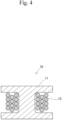
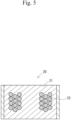
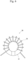
- Inductors 10, 20, and 30 shown in Fig. 4 to Fig. 6 are examples of the electronic element in the present disclosure.
- the inductor 10 shown in Fig. 4 includes a dust core 11 and a coil 13.
- the inductor 20 shown in Fig. 5 includes a dust core 21 and a coil 23.
- the inductor 30 shown in Fig. 6 includes a dust core 31 and a coil 33.
- the dust cores 11, 21, and 31 each have the same configuration as that of the dust core 1.
- a noise filter 40 shown in Fig. 7 is an example of the electronic element in the present disclosure.
- the noise filter 40 includes a dust core 41 and a pair of coils 43 and 45.
- the dust core 41 has the same configuration as that of the dust core 1.
- a reactor 50 shown in Fig. 8 is an example of the electronic element in the present disclosure.
- the reactor 50 includes a dust core 51 and coils 53.
- the dust core 51 has the same configuration as that of the dust core 1.
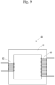
- a transformer 60 shown in Fig. 9 is an example of the electronic element in the present disclosure.
- the transformer 60 includes a dust core 61 and a pair of coils 63 and 65.
- the dust core 61 has the same configuration as that of the above dust core 1.
- the above dust core 1 is suitably used for an electronic device.
- the electronic device includes an electronic element.
- Examples of the electronic element include the above electronic elements.
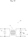
- a noise filter 70 shown in Fig. 10 is an example of the electronic device in the present disclosure.
- the noise filter 70 includes an element 71 and capacitors 73, 75, and 77.
- the element 71 corresponds to an example of the "electronic element" in the present disclosure.
- the element 71 is, for example, an element having the same configuration as that of the noise filter 40 shown in Fig. 7 .
- the above dust core 1 is suitably used for an electric motor.
- the electric motor include motors, linear actuators, and the like.
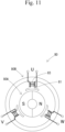
- a motor 80 shown in Fig. 11 is an example of the electric motor in the present disclosure.
- the motor 80 includes a rotor 80A and a stator 80B.
- the stator 80B has a dust core 81 and coils 83.
- the dust core 81 has the same configuration as that of the above dust core 1.
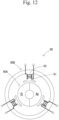
- An electric generator 90 shown in Fig. 12 is an example of an electric generator in the present disclosure.
- the electric generator 90 includes a rotor 90A and a stator 90B.
- the stator 90B has a dust core 91 and coils 93.
- the dust core 91 has the same configuration as that of the above dust core 1.
- Example 2 after the core portions were coated, the coated core portions were compacted at 1 GPa and annealed while being kept at 1000°C for 1.5 hours. In a cooling step, cooling from 600°C to 300°C was performed at a cooling speed of 2°C/min.
- Example 3 after the core portions were coated, the coated core portions were heated in powder form while being kept at 900°C for 1.5 hours and were cooled. In this cooling step, cooling from 600°C to 300°C was performed at a cooling speed of 2°C/min. Thereafter, the powder was compacted at 1 GPa, was annealed while being kept at 1000°C for 1.5 hours, and was cooled. In this cooling step, cooling from 600°C to 300°C was performed at a cooling speed of 2°C/min.
- Comparative Example 1 after the core portions were coated, the coated core portions were compacted at 1 GPa and annealed while being kept at 600°C for 0.5 hours. In a cooling step, cooling from 600°C to 300°C was performed at a cooling speed of 1°C/min.
- Comparative Example 2 after the core portions were coated, the coated core portions were compacted at 1 GPa and annealed while being kept at 600°C for 1.5 hours. In a cooling step, cooling from 600°C to 300°C was performed at a cooling speed of 1°C/min.
- Example 5 after the core portions were coated, the coated core portions were heated in powder form while being kept at 900°C for 1.5 hours and were cooled. In this cooling step, cooling from 600°C to 300°C was performed at a cooling speed of 2°C/min. Thereafter, the powder was compacted at 1 GPa, was annealed while being kept at 1050°C for 2.0 hours, and was cooled. In this cooling step, cooling from 600°C to 300°C was performed at a cooling speed of 2°C/min.
- Comparative Example 4 core portions containing 1.0% by mass of silicon, with the remainder being iron and inevitable impurities, were used as a raw material powder and coated with MnZn ferrite through the plating method. After the core portions were coated, the coated core portions were compacted at 1 GPa and annealed while being kept at 1050°C for 1.5 hours. In a cooling step, cooling from 600°C to 300°C was performed at a cooling speed of 2°C/min.
- the relative permeability of each of the dust cores was measured by using the measurement device (B-H analyzer (model number: SY-8218) manufactured by IWATSU ELECTRIC CO., LTD.). The relative permeability was evaluated under the conditions of 0.1 T and 10 kHz.
- Comparative Examples 1 and 2 do not satisfy the above requirements (A) to (C).
- Fe 3 O 4 of a spinel type was observed as a crystalline phase of the coating portion, and no metal particles were observed.
- the metal particles were present not in a scattered manner but in a connected state.
- the eddy-current losses in Examples 1 to 3 which satisfy the above requirements (A) to (C) were respectively 1.8 kW/m 3 , 1.9 kW/m 3 , and 1.8 kW/m 3 .
- the eddy-current losses in Comparative Examples 1 and 2 which do not satisfy the above requirements (A) to (C) were respectively 9.3 kW/m 3 and 7.8 kW/m 3 . It is considered that, in each of Examples 1 to 3, the coating portion of each of the alloy particles did not contain iron oxide but contained Fe 2 SiO 4 , and thus insulation properties between the alloy particles were high and the eddy-current loss was able to be decreased.
- the plurality of metal particles was present in a scattered manner in a state of being held between the coating portions of adjacent ones of the alloy particles, and thus the metal particles were less likely to be a path for eddy current and the eddy-current loss was able to be decreased.
- the annealing temperature was as low as 600°C and the annealing time was as short as 0.5 hours, and thus a reaction of forming Fe 2 SiO 4 was less likely to progress and the eddy-current loss was increased.
- the indexes of strengths obtained through three-point bending tests in each of Examples 1 to 3 which satisfy the above requirements (A) to (C) were 58 MPa to 80 MPa.
- the indexes of strengths obtained in three-point bending tests in Comparative Examples 1 and 2 which do not satisfy the above requirements (A) to (C) were respectively 35 MPa and 61 MPa. It is considered that, in each of Examples 1 to 3, the metal particles each had a low silicon concentration and were deformed at the time of compacting so that the alloy particles were easily bound to each other, whereby the strength was increased.
- the coating portion of each of the alloy particles contained Fe 2 SiO 4 having a lower melting point than iron oxide, and thus the coating portions were easily sintered together, whereby the strength was increased.
- the relative permeability in each of Examples 1 to 3 which satisfy the above requirements (A) to (C) was 62 to 80.
- the relative permeabilities in Comparative Examples 1 and 2 which do not satisfy the above requirements (A) to (C) were respectively 40 and 65. It is considered that, in each of Examples 1 to 3, the plurality of metal particles was present in a scattered manner in a state of being held between the coating portions of adjacent ones of the alloy particles, and the alloy particles were magnetically bound to each other, whereby the relative permeability was increased.
- Comparative Examples 3 and 4 do not satisfy the above requirements (D) to (F).
- MgFeSiO 4 was observed as a crystalline phase of the coating portion, but the metal particles were present not in a scattered manner but in a connected state.
- Fe 2 SiO 4 was observed as a crystalline phase of the coating portion, but the metal particles were present not in a scattered manner but in a connected state.
- the eddy-current losses in Examples 4 and 5 which satisfy the above requirements (D) to (F) were respectively 1.8 kW/m 3 and 1.9 kW/m 3 .
- the eddy-current losses in Comparative Examples 3 and 4 which do not satisfy the above requirements (D) to (F) were respectively 350 kW/m 3 and 450 kW/m 3 . It is considered that, in each of Examples 4 and 5, the coating portion of each of the alloy particles did not contain iron oxide but contained a solid-solved body of Fe 2 SiO 4 and Mg 2 SiO 4 , and thus insulation properties between the alloy particles were high and the eddy-current loss was able to be decreased.
- each of the core portions had a lower Si content than those in Examples 4 and 5, and the alloy included in the core portion underwent A 3 transformation from an ⁇ phase to a ⁇ phase in the annealing step.
- this transformation led to generation of a minute crack in the coating portion and caused sintering between adjacent ones of the alloy particles through the crack, whereby the insulation properties were decreased and the eddy-current loss was increased.
- the indexes of strengths obtained in three-point bending tests in Examples 4 and 5 which satisfy the above requirements (D) to (F) were respectively 74 MPa and 85 MPa.
- strengths approximately equal to those in Examples 1 to 3 were obtained.
- the metal particles each had a low silicon concentration and were deformed at the time of compacting so that the alloy particles were easily bound to each other, whereby the strength was increased.
- the coating portion of each of the alloy particles contained a solid-solved body of Fe 2 SiO 4 and Mg 2 SiO 4 having a lower melting point than iron oxide, and thus the coating portions were easily sintered together, whereby the strength was increased.
- Examples 4 and 5 which satisfy the above requirements (D) to (F) were respectively 57 and 61.
- Examples 4 and 5 relative permeabilities approximately equal to those in Examples 1 to 3 were obtained. It is considered that, in each of Examples 4 and 5, the plurality of metal particles was present in a scattered manner in a state of being held between the coating portions of adjacent ones of the alloy particles, and the alloy particles were magnetically bound to each other, whereby the relative permeability was increased.
- the dust core in each of these Examples sustained low eddy-current loss and had high strength and high relative permeability.
Landscapes
- Engineering & Computer Science (AREA)
- Chemical & Material Sciences (AREA)
- Power Engineering (AREA)
- Mechanical Engineering (AREA)
- Materials Engineering (AREA)
- Metallurgy (AREA)
- Organic Chemistry (AREA)
- Dispersion Chemistry (AREA)
- Physics & Mathematics (AREA)
- Manufacturing & Machinery (AREA)
- Thermal Sciences (AREA)
- Crystallography & Structural Chemistry (AREA)
- Electromagnetism (AREA)
- Soft Magnetic Materials (AREA)
- Powder Metallurgy (AREA)
Applications Claiming Priority (3)
| Application Number | Priority Date | Filing Date | Title |
|---|---|---|---|
| JP2022137770 | 2022-08-31 | ||
| JP2023002295A JP2024035021A (ja) | 2022-08-31 | 2023-01-11 | 圧粉磁心、合金粒子、電子素子、電子機器、電動機および発電機 |
| PCT/JP2023/029024 WO2024048226A1 (ja) | 2022-08-31 | 2023-08-09 | 圧粉磁心、合金粒子、電子素子、電子機器、電動機および発電機 |
Publications (1)
| Publication Number | Publication Date |
|---|---|
| EP4583129A1 true EP4583129A1 (de) | 2025-07-09 |
Family
ID=90099349
Family Applications (1)
| Application Number | Title | Priority Date | Filing Date |
|---|---|---|---|
| EP23859993.0A Pending EP4583129A1 (de) | 2022-08-31 | 2023-08-09 | Pulverkern, legierungspartikel, elektronisches element, elektronische vorrichtung, elektromotor und dynamo |
Country Status (6)
| Country | Link |
|---|---|
| US (1) | US20250336580A1 (de) |
| EP (1) | EP4583129A1 (de) |
| KR (1) | KR102927257B1 (de) |
| CN (1) | CN119631149A (de) |
| TW (1) | TW202423571A (de) |
| WO (1) | WO2024048226A1 (de) |
Family Cites Families (9)
| Publication number | Priority date | Publication date | Assignee | Title |
|---|---|---|---|---|
| JP4328885B2 (ja) * | 2003-11-04 | 2009-09-09 | 国立大学法人東京工業大学 | フェライトめっきされたセンダスト微粒子およびその成形体の製造方法 |
| JP2006128307A (ja) * | 2004-10-27 | 2006-05-18 | Fuji Electric Holdings Co Ltd | 軟磁性成形体の製造方法 |
| JP4609339B2 (ja) | 2006-02-09 | 2011-01-12 | トヨタ自動車株式会社 | 圧粉磁心用粉末および圧粉磁心の製造方法 |
| JP5916392B2 (ja) | 2012-01-17 | 2016-05-11 | 株式会社日立産機システム | 圧粉軟磁性体、圧粉磁性体の製造方法、及びモータ |
| JP6075605B2 (ja) | 2012-09-14 | 2017-02-08 | アイシン精機株式会社 | 軟磁性体及びその製造方法 |
| JP6492534B2 (ja) | 2014-10-28 | 2019-04-03 | アイシン精機株式会社 | 軟磁性体の製造方法 |
| JP6836846B2 (ja) * | 2015-12-24 | 2021-03-03 | 株式会社デンソー | 圧粉磁心用粉末の製造方法および圧粉磁心の製造方法 |
| JP6930722B2 (ja) | 2017-06-26 | 2021-09-01 | 太陽誘電株式会社 | 磁性材料、電子部品及び磁性材料の製造方法 |
| DE112018004572T8 (de) | 2017-10-17 | 2020-07-30 | Denso Corporation | Komprimierter pulver-magnetkern, pulver für magnetischen kern, und deren herstellungsverfahren |
-
2023
- 2023-08-09 WO PCT/JP2023/029024 patent/WO2024048226A1/ja not_active Ceased
- 2023-08-09 EP EP23859993.0A patent/EP4583129A1/de active Pending
- 2023-08-09 US US18/867,554 patent/US20250336580A1/en active Pending
- 2023-08-09 KR KR1020257000871A patent/KR102927257B1/ko active Active
- 2023-08-09 CN CN202380056081.4A patent/CN119631149A/zh active Pending
- 2023-08-28 TW TW112132319A patent/TW202423571A/zh unknown
Also Published As
| Publication number | Publication date |
|---|---|
| CN119631149A (zh) | 2025-03-14 |
| WO2024048226A1 (ja) | 2024-03-07 |
| KR102927257B1 (ko) | 2026-02-12 |
| TW202423571A (zh) | 2024-06-16 |
| US20250336580A1 (en) | 2025-10-30 |
| KR20250021563A (ko) | 2025-02-13 |
Similar Documents
| Publication | Publication Date | Title |
|---|---|---|
| US7682695B2 (en) | Dust core with specific relationship between particle diameter and coating thickness, and method for producing same | |
| EP2518740B1 (de) | Herstellungsverfahren eines reaktors | |
| JP6075605B2 (ja) | 軟磁性体及びその製造方法 | |
| EP2680281A1 (de) | Weichmagnetisches verbundmaterial mit niedriger magnetkraft und hoher magnetflussdichte, herstellungsverfahren dafür und elektromagnetische schaltungskomponente | |
| EP2947670A1 (de) | Verfahren zur herstellung eines magnetpulverkerns, magnetpulverkern und spulenkomponente | |
| US20120138844A1 (en) | IRON POWDER COATED WITH Mg-CONTAINING OXIDE FILM | |
| EP2060344A1 (de) | Magnetpulverkern und pulver auf eisenbasis für magnetpulverkern | |
| EP2434502A1 (de) | Magnetischer verbundstoffkörper und herstellungsverfahren dafür | |
| EP1918943B1 (de) | Verfahren zur herstellung eines weichmagnetischen materials und verfahren zur herstellung eines magnetischen pulverkerns | |
| EP1716946A1 (de) | Weichmagnetisches material und pulverkern | |
| EP4583129A1 (de) | Pulverkern, legierungspartikel, elektronisches element, elektronische vorrichtung, elektromotor und dynamo | |
| EP1675136B1 (de) | Weichmagnetisches material und pulver-magnetkern | |
| JP2007012745A (ja) | 圧粉磁心およびその製造方法 | |
| US11699542B2 (en) | Dust core | |
| EP4641593A1 (de) | Legierungspartikel, pulvermagnetkern, elektronisches element, elektronische vorrichtung, elektromotor und dynamo | |
| EP1675137A1 (de) | Prozess zur herstellung von weichmagnetischem material, weichmagnetisches material und pulver-magnetkern | |
| JP4586399B2 (ja) | 軟磁性材料、圧粉磁心、および軟磁性材料の製造方法 | |
| JP2021036577A (ja) | 圧粉磁芯 | |
| JP2024035021A (ja) | 圧粉磁心、合金粒子、電子素子、電子機器、電動機および発電機 | |
| US20150017056A1 (en) | Soft magnetic metal powder, method for preparing the same, and electronic components including the same as core material | |
| EP4447075A1 (de) | Beschichtetes magnetisches material und verfahren zur herstellung eines beschichteten magnetischen materials | |
| JP2007129093A (ja) | 軟磁性材料およびこれを用いて製造された圧粉磁心 |
Legal Events
| Date | Code | Title | Description |
|---|---|---|---|
| STAA | Information on the status of an ep patent application or granted ep patent |
Free format text: STATUS: THE INTERNATIONAL PUBLICATION HAS BEEN MADE |
|
| PUAI | Public reference made under article 153(3) epc to a published international application that has entered the european phase |
Free format text: ORIGINAL CODE: 0009012 |
|
| STAA | Information on the status of an ep patent application or granted ep patent |
Free format text: STATUS: REQUEST FOR EXAMINATION WAS MADE |
|
| 17P | Request for examination filed |
Effective date: 20250328 |
|
| AK | Designated contracting states |
Kind code of ref document: A1 Designated state(s): AL AT BE BG CH CY CZ DE DK EE ES FI FR GB GR HR HU IE IS IT LI LT LU LV MC ME MK MT NL NO PL PT RO RS SE SI SK SM TR |
|
| DAV | Request for validation of the european patent (deleted) | ||
| DAX | Request for extension of the european patent (deleted) |