EP4582832A2 - Mimo-radarübertragung und signalverarbeitung - Google Patents
Mimo-radarübertragung und signalverarbeitung Download PDFInfo
- Publication number
- EP4582832A2 EP4582832A2 EP24216768.2A EP24216768A EP4582832A2 EP 4582832 A2 EP4582832 A2 EP 4582832A2 EP 24216768 A EP24216768 A EP 24216768A EP 4582832 A2 EP4582832 A2 EP 4582832A2
- Authority
- EP
- European Patent Office
- Prior art keywords
- phase
- signal
- radar
- conjugate
- rotators
- Prior art date
- Legal status (The legal status is an assumption and is not a legal conclusion. Google has not performed a legal analysis and makes no representation as to the accuracy of the status listed.)
- Pending
Links
Images


Classifications
-
- G—PHYSICS
- G01—MEASURING; TESTING
- G01S—RADIO DIRECTION-FINDING; RADIO NAVIGATION; DETERMINING DISTANCE OR VELOCITY BY USE OF RADIO WAVES; LOCATING OR PRESENCE-DETECTING BY USE OF THE REFLECTION OR RERADIATION OF RADIO WAVES; ANALOGOUS ARRANGEMENTS USING OTHER WAVES
- G01S13/00—Systems using the reflection or reradiation of radio waves, e.g. radar systems; Analogous systems using reflection or reradiation of waves whose nature or wavelength is irrelevant or unspecified
- G01S13/02—Systems using reflection of radio waves, e.g. primary radar systems; Analogous systems
- G01S13/06—Systems determining position data of a target
- G01S13/46—Indirect determination of position data
- G01S13/48—Indirect determination of position data using multiple beams at emission or reception
-
- G—PHYSICS
- G01—MEASURING; TESTING
- G01S—RADIO DIRECTION-FINDING; RADIO NAVIGATION; DETERMINING DISTANCE OR VELOCITY BY USE OF RADIO WAVES; LOCATING OR PRESENCE-DETECTING BY USE OF THE REFLECTION OR RERADIATION OF RADIO WAVES; ANALOGOUS ARRANGEMENTS USING OTHER WAVES
- G01S7/00—Details of systems according to groups G01S13/00, G01S15/00, G01S17/00
- G01S7/02—Details of systems according to groups G01S13/00, G01S15/00, G01S17/00 of systems according to group G01S13/00
- G01S7/28—Details of pulse systems
- G01S7/282—Transmitters
-
- G—PHYSICS
- G01—MEASURING; TESTING
- G01S—RADIO DIRECTION-FINDING; RADIO NAVIGATION; DETERMINING DISTANCE OR VELOCITY BY USE OF RADIO WAVES; LOCATING OR PRESENCE-DETECTING BY USE OF THE REFLECTION OR RERADIATION OF RADIO WAVES; ANALOGOUS ARRANGEMENTS USING OTHER WAVES
- G01S13/00—Systems using the reflection or reradiation of radio waves, e.g. radar systems; Analogous systems using reflection or reradiation of waves whose nature or wavelength is irrelevant or unspecified
- G01S13/02—Systems using reflection of radio waves, e.g. primary radar systems; Analogous systems
- G01S13/06—Systems determining position data of a target
- G01S13/08—Systems for measuring distance only
- G01S13/10—Systems for measuring distance only using transmission of interrupted, pulse modulated waves
- G01S13/26—Systems for measuring distance only using transmission of interrupted, pulse modulated waves wherein the transmitted pulses use a frequency- or phase-modulated carrier wave
- G01S13/28—Systems for measuring distance only using transmission of interrupted, pulse modulated waves wherein the transmitted pulses use a frequency- or phase-modulated carrier wave with time compression of received pulses
- G01S13/282—Systems for measuring distance only using transmission of interrupted, pulse modulated waves wherein the transmitted pulses use a frequency- or phase-modulated carrier wave with time compression of received pulses using a frequency modulated carrier wave
-
- G—PHYSICS
- G01—MEASURING; TESTING
- G01S—RADIO DIRECTION-FINDING; RADIO NAVIGATION; DETERMINING DISTANCE OR VELOCITY BY USE OF RADIO WAVES; LOCATING OR PRESENCE-DETECTING BY USE OF THE REFLECTION OR RERADIATION OF RADIO WAVES; ANALOGOUS ARRANGEMENTS USING OTHER WAVES
- G01S13/00—Systems using the reflection or reradiation of radio waves, e.g. radar systems; Analogous systems using reflection or reradiation of waves whose nature or wavelength is irrelevant or unspecified
- G01S13/88—Radar or analogous systems specially adapted for specific applications
- G01S13/93—Radar or analogous systems specially adapted for specific applications for anti-collision purposes
- G01S13/931—Radar or analogous systems specially adapted for specific applications for anti-collision purposes of land vehicles
-
- G—PHYSICS
- G01—MEASURING; TESTING
- G01S—RADIO DIRECTION-FINDING; RADIO NAVIGATION; DETERMINING DISTANCE OR VELOCITY BY USE OF RADIO WAVES; LOCATING OR PRESENCE-DETECTING BY USE OF THE REFLECTION OR RERADIATION OF RADIO WAVES; ANALOGOUS ARRANGEMENTS USING OTHER WAVES
- G01S7/00—Details of systems according to groups G01S13/00, G01S15/00, G01S17/00
- G01S7/02—Details of systems according to groups G01S13/00, G01S15/00, G01S17/00 of systems according to group G01S13/00
-
- G—PHYSICS
- G01—MEASURING; TESTING
- G01S—RADIO DIRECTION-FINDING; RADIO NAVIGATION; DETERMINING DISTANCE OR VELOCITY BY USE OF RADIO WAVES; LOCATING OR PRESENCE-DETECTING BY USE OF THE REFLECTION OR RERADIATION OF RADIO WAVES; ANALOGOUS ARRANGEMENTS USING OTHER WAVES
- G01S7/00—Details of systems according to groups G01S13/00, G01S15/00, G01S17/00
- G01S7/02—Details of systems according to groups G01S13/00, G01S15/00, G01S17/00 of systems according to group G01S13/00
- G01S7/28—Details of pulse systems
- G01S7/285—Receivers
-
- G—PHYSICS
- G01—MEASURING; TESTING
- G01S—RADIO DIRECTION-FINDING; RADIO NAVIGATION; DETERMINING DISTANCE OR VELOCITY BY USE OF RADIO WAVES; LOCATING OR PRESENCE-DETECTING BY USE OF THE REFLECTION OR RERADIATION OF RADIO WAVES; ANALOGOUS ARRANGEMENTS USING OTHER WAVES
- G01S7/00—Details of systems according to groups G01S13/00, G01S15/00, G01S17/00
- G01S7/02—Details of systems according to groups G01S13/00, G01S15/00, G01S17/00 of systems according to group G01S13/00
- G01S7/28—Details of pulse systems
- G01S7/285—Receivers
- G01S7/288—Coherent receivers
- G01S7/2883—Coherent receivers using FFT processing
-
- G—PHYSICS
- G01—MEASURING; TESTING
- G01S—RADIO DIRECTION-FINDING; RADIO NAVIGATION; DETERMINING DISTANCE OR VELOCITY BY USE OF RADIO WAVES; LOCATING OR PRESENCE-DETECTING BY USE OF THE REFLECTION OR RERADIATION OF RADIO WAVES; ANALOGOUS ARRANGEMENTS USING OTHER WAVES
- G01S7/00—Details of systems according to groups G01S13/00, G01S15/00, G01S17/00
- G01S7/02—Details of systems according to groups G01S13/00, G01S15/00, G01S17/00 of systems according to group G01S13/00
- G01S7/35—Details of non-pulse systems
Definitions
- each TX element is coupled to one of a corresponding number of phase rotators, and a digital controller implements a MIMO radar modulation scheme by controlling each one of the phase rotators to apply a different phase code to the signal that is transmitted from every TX element.
- a radar system includes a radar front end with a plurality of transmit antennas that each are coupled to a power amplifier of a plurality of amplifiers.
- the radar front end also includes a plurality of phase rotators, and each phase rotator is coupled to multiple power amplifiers (e.g., two) of the plurality of power amplifiers.
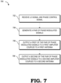
- Each phase rotator is configured to generate multiple phase modulated signals based on a phase control signal and a local oscillator signal, and each one of the multiple phase modulated signals is input to a respective one of the multiple amplifiers that the phase rotator is coupled to.
- a single phase rotator generates a plurality of phase modulated signals that are then relayed to multiple transmit antennas for transmission. This reduces the number of phase rotators used in the radar front end.
- a first phase rotator is coupled to a first and a second power amplifier, and a second phase rotator is coupled to a third and a fourth power amplifier.
- Each one of the four power amplifiers is coupled to one of four TX elements.
- Each one of the first and second phase rotators are conjugate phase rotators that output a pair of phase modulated signals based on two inputs: a local oscillator signal that is common to all the phase rotators and a phase control signal received from a digital controller that is specific to the corresponding phase rotators.
- any of the elements, components, or blocks shown in the ensuing figures are implemented as one of software executing on a processor, hardware that is hard-wired (e.g., circuitry) to perform the various operations described herein, or a combination thereof.
- one or more of the described blocks or components represent software instructions that are executed by hardware such as a digital signal processor, an application-specific integrated circuit (ASIC), a set of logic gates, a field programmable gate array (FPGA), programmable logic device (PLD), a hardware accelerator, a parallel processor, or any other type of hardcoded or programmable circuit.
- ASIC application-specific integrated circuit
- FPGA field programmable gate array
- PLD programmable logic device
- a hardware accelerator e.g., programmable logic device
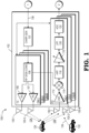
- the radar front end 102 includes multiple transmitters 104-1 to 104-N (collectively referred to as transmitters 104).
- each transmitter 104 includes a plurality of power amplifiers (PAs) 106, 107 and a radio frequency (RF) conditioning (cond.) component 108.
- PAs power amplifiers
- RF radio frequency
- the PAs 106, 107 convert a lower power RF signal into a higher power RF signal prior to transmission.
- the PAs 106, 107 are configured to convert a lower power RF signal including a plurality of chirps into a higher power RF signal.
- the radar front end 102 receives program, control trigger, and reference clock signals 136 that are utilized for chirp generation at a chirp generator 137 or received signal processing in the receivers 110.
- the reference clock signal is a local oscillator (LO) signal
- the control trigger is a chirp start trigger signal that are input to the chirp generator 137 to generate radar chirp sequences that are further processed (e.g., by RF conditioning component 108 and PAs 106, 107) before being transmitted by the transmit antennas 120 of the radar front end 102.
- the chirp generator 137 includes a phase locked loop (PLL) that generates linear frequency modulated chirp sequences.
- the PLL in the chirp generator 137 generates an FMCW chirp sequence for transmission by the transmitters 104.
- the radar front end 102 also includes transmission antennas 120.
- each transmitter 104 is configured with its own transmission antennas 120 (e.g., transmitter 104-1 with transmission antennas 120-1, 120-2).
- Transmitters 104 send transmitted signals 124 toward one or more targets 126 (one labeled for clarity).
- the transmitted signals are reflected from the target 126, and the target reflected signals 128 (collectively referred to as target radar signal, radar reflections, or the like) are directed back to the radar system 100.
- the target reflected signals 128 are received by reception antennas 130-1 to 130-M.
- each receiver 110 is configured with its own reception antenna 130 (e.g., receiver 110-1 with reception antenna 130-1, receiver 110-2 with reception antenna 130-2, receiver 110-M with reception antenna 130-M).
- the receivers 110 may receive other unwanted signals.
- an interferer 132 in this example, radar signals from another vehicle transmits interference 134 which is also received by the receivers 110.
- the radar front end 102 also includes multiple receivers 110-1 to 110-M (collectively referred to as receivers 110).
- receivers 110 includes a low noise amplifier (LNA) 112, a deramp mixer 114 , a high pass filter (HPF) 116, a variable gain power amplifier 118, a low pass filter (LPF) 120, and an analog-to-digital converter (ADC) 122 that digitizes the received radar signal prior to providing it to a radar signal processor for estimating a range and velocity of the targets 126.
- LNA low noise amplifier
- HPF high pass filter
- LPF variable gain power amplifier
- LPF low pass filter
- ADC analog-to-digital converter
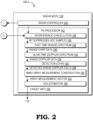
- the radar system 100 includes a radar master controller processing unit (MCPU) 138.
- the radar MCPU 138 includes a radar controller 140 and a receiver (RX) processor 142.
- the radar controller 140 provides the program, control trigger, and reference clock signals 136 as described above.
- the receiver processor 140 receives the digitized signals from the radar front end 102, e.g., from the ADCs 122 of the receivers 110.
- the RX processor 140 includes an interference cancellation component 144, which provides the interference suppressed ADC samples 146.
- a fast-time (Range) spectrum component 148 receives and processes the interference suppressed ADC samples 146.
- the fast-time spectrum component 148 applies an FFT over the fast-time index of the windowed samples to provide range chirp data 150 indicative of chirp reflections received at the reception antennas 130.
- the range chirp data 150 is cubed with an x-axis and a y-axis made up of fast time data and a z-axis representing data for each of the reception antennas 130.
- the range chirp data 150 is received and processed by a slow-time (velocity, or Doppler) spectrum component 152.
- the slow-time spectrum component 152 applies an FFT over the slow-time index of the windowed samples.
- the slow time spectrum component 152 provides range-Doppler data 154 that is cubed with x-axis and y-axis made up of slow time data and a z-axis representing data for each of the reception antennas 130.
- the range Doppler data 154 is received and processed by a constant false alarm rate (CFAR) detection component 154.
- the detection component 154 provides detected range and Doppler cell data 158.
- a multiple-input multiple-output (MIMO) array measurement construction component 160 receives and processes the detected range and Doppler cell data 158.
- the MIMO array measurement construction component 160 provides an array measurement vector 162.
- the array measurement vector is received and processed by a target Angle of Arrival (AoA) estimation component 164.
- AoA target Angle of Arrival
- the target AoA estimation component 164 provides target information 166 attributed to the target 126 detected by radar system 100 to other components via data interface 170.
- the other components include software modules executed by a processor to implement advanced driver assistant system (ADAS) or autonomous driving (AD) perception and vehicular control systems.
- ADAS advanced driver assistant system
- AD autonomous driving
- the radar system 100 including the radar front end 102 and the radar MCPU 138 are configured to implement the transmit signal phase modulation techniques and corresponding signal processing techniques described herein.
- the transmitters 104 include one or more conjugate phase rotators that are each configured to generate multiple phase modulated signals based on a common local oscillator signal and a phase control signal. Each one of the multiple phase modulated signals is then input to a different power amplifier that is coupled to one of a plurality of transmit antennas of the radar front end 102. In this manner, the number of phase rotators in the radar front end is reduced while still allowing for MIMO radar implementation.
- FIG. 3 shows an example of a vehicular control system 300 in accordance with some embodiments.
- the vehicular control system 300 is implemented, for example, in an automobile and may be used to assist in driver-assistance or autonomous driving functions.
- the vehicular control system 300 includes a radar system 301 which includes radar front ends 306, 308 and a radar MCPU 304.
- radar front ends 306, 308 correspond to radar front end 102 in FIG. 1
- radar MCPU 304 corresponds to radar MCPU 138 in FIG. 2 .
Landscapes
- Engineering & Computer Science (AREA)
- Radar, Positioning & Navigation (AREA)
- Remote Sensing (AREA)
- Physics & Mathematics (AREA)
- Computer Networks & Wireless Communication (AREA)
- General Physics & Mathematics (AREA)
- Electromagnetism (AREA)
- Radar Systems Or Details Thereof (AREA)
- Amplifiers (AREA)
Applications Claiming Priority (1)
| Application Number | Priority Date | Filing Date | Title |
|---|---|---|---|
| US18/539,578 US20250199152A1 (en) | 2023-12-14 | 2023-12-14 | Mimo radar transmission and signal processing |
Publications (2)
| Publication Number | Publication Date |
|---|---|
| EP4582832A2 true EP4582832A2 (de) | 2025-07-09 |
| EP4582832A3 EP4582832A3 (de) | 2025-11-05 |
Family
ID=93743892
Family Applications (1)
| Application Number | Title | Priority Date | Filing Date |
|---|---|---|---|
| EP24216768.2A Pending EP4582832A3 (de) | 2023-12-14 | 2024-12-02 | Mimo-radarübertragung und signalverarbeitung |
Country Status (3)
| Country | Link |
|---|---|
| US (1) | US20250199152A1 (de) |
| EP (1) | EP4582832A3 (de) |
| CN (1) | CN120161416A (de) |
Family Cites Families (8)
| Publication number | Priority date | Publication date | Assignee | Title |
|---|---|---|---|---|
| GB0205199D0 (en) * | 2002-03-06 | 2002-04-17 | Univ Belfast | Modulator/transmitter apparatus and method |
| JP6105473B2 (ja) * | 2011-08-12 | 2017-03-29 | パナソニック株式会社 | レーダ装置 |
| US9929886B2 (en) * | 2016-06-06 | 2018-03-27 | Intel Corporation | Phased array antenna cell with adaptive quad polarization |
| EP3301470A3 (de) * | 2016-09-29 | 2018-06-20 | Panasonic Corporation | Multiradarsystem |
| JP6917735B2 (ja) * | 2017-03-07 | 2021-08-11 | パナソニック株式会社 | レーダ装置及びレーダ方法 |
| EP3483622B1 (de) * | 2017-11-10 | 2020-08-05 | Nxp B.V. | Radareinheit mit eingebautem selbsttest |
| US11545950B2 (en) * | 2019-06-03 | 2023-01-03 | Analog Devices, Inc. | Apparatus and methods for vector modulator phase shifters |
| US11662427B2 (en) * | 2019-12-09 | 2023-05-30 | Nxp Usa, Inc. | Method and system for frequency offset modulation range division MIMO automotive radar |
-
2023
- 2023-12-14 US US18/539,578 patent/US20250199152A1/en active Pending
-
2024
- 2024-12-02 EP EP24216768.2A patent/EP4582832A3/de active Pending
- 2024-12-11 CN CN202411819498.4A patent/CN120161416A/zh active Pending
Also Published As
| Publication number | Publication date |
|---|---|
| US20250199152A1 (en) | 2025-06-19 |
| EP4582832A3 (de) | 2025-11-05 |
| CN120161416A (zh) | 2025-06-17 |
Similar Documents
| Publication | Publication Date | Title |
|---|---|---|
| US11662427B2 (en) | Method and system for frequency offset modulation range division MIMO automotive radar | |
| EP3835809B1 (de) | Verfahren und system für frequenzversatz-modulationsbereichsteilungs-mimo-automobilradar unter verwendung eines nur-i-kanalmodulationsmischers | |
| JP4833534B2 (ja) | レーダ装置 | |
| CN113567928A (zh) | Mimo雷达装置和mimo雷达方法 | |
| JP5537654B2 (ja) | 多重チャンネル受信機システム、レーダーシステム、及び車両 | |
| US9933520B1 (en) | Orthogonal linear frequency modulation for MIMO radar | |
| CN109932722A (zh) | 用于消除干扰信号的设备和方法 | |
| EP3572838A1 (de) | Radardienst | |
| US20240361445A1 (en) | Updating radar sensor accuracy measurements for object tracking | |
| US20150219751A1 (en) | System And Method For Avoiding DC Bias In A Homodyne Receiver | |
| US20240402324A1 (en) | Mimo radar apparatus and mimo radar method | |
| US11988770B2 (en) | Phase-modulated continuous wave radar receiver with time division quadrature sampling | |
| US20210025969A1 (en) | Radar device | |
| US12566256B2 (en) | Multiple-input, multiple-output radar system with range-doppler circulating chirps | |
| EP4053585B1 (de) | Frequenzmultiplexen mit polyphasenschiebern | |
| EP4053586A1 (de) | Frequenzmultiplexen mit polyphasenschiebern | |
| EP4575549A1 (de) | Radarübertragungs- und signalverarbeitungsverfahren mit chirp-steigungsvariation | |
| EP4582832A2 (de) | Mimo-radarübertragung und signalverarbeitung | |
| EP4571350A1 (de) | Formung und verarbeitung der radarsignalübertragungsleistung | |
| EP4538733A1 (de) | Hybrides zufalls-zeitmultiplex-radarsystem und verfahren mit multiple-input-multiple-output (mimo) und doppler-multiplex-verfahren | |
| CN116034286A (zh) | 雷达装置 | |
| JP3780904B2 (ja) | レーダ装置 | |
| EP4641253A1 (de) | Verfahren zur schätzung der objektmenge in mimo-radarsystemen | |
| US20250216540A1 (en) | Mimo radar with object reflected signal overlap detection | |
| US20250060470A1 (en) | Digital chirp ofdm radar and radar sensing methods |
Legal Events
| Date | Code | Title | Description |
|---|---|---|---|
| PUAI | Public reference made under article 153(3) epc to a published international application that has entered the european phase |
Free format text: ORIGINAL CODE: 0009012 |
|
| STAA | Information on the status of an ep patent application or granted ep patent |
Free format text: STATUS: THE APPLICATION HAS BEEN PUBLISHED |
|
| AK | Designated contracting states |
Kind code of ref document: A2 Designated state(s): AL AT BE BG CH CY CZ DE DK EE ES FI FR GB GR HR HU IE IS IT LI LT LU LV MC ME MK MT NL NO PL PT RO RS SE SI SK SM TR |
|
| PUAL | Search report despatched |
Free format text: ORIGINAL CODE: 0009013 |
|
| AK | Designated contracting states |
Kind code of ref document: A3 Designated state(s): AL AT BE BG CH CY CZ DE DK EE ES FI FR GB GR HR HU IE IS IT LI LT LU LV MC ME MK MT NL NO PL PT RO RS SE SI SK SM TR |
|
| RIC1 | Information provided on ipc code assigned before grant |
Ipc: G01S 7/282 20060101AFI20251001BHEP Ipc: G01S 7/35 20060101ALI20251001BHEP Ipc: G01S 13/931 20200101ALI20251001BHEP |