EP4582829A1 - Flotteninterne interferenzabschwächung mit radaruneindeutigen phasencodes - Google Patents
Flotteninterne interferenzabschwächung mit radaruneindeutigen phasencodes Download PDFInfo
- Publication number
- EP4582829A1 EP4582829A1 EP24150374.7A EP24150374A EP4582829A1 EP 4582829 A1 EP4582829 A1 EP 4582829A1 EP 24150374 A EP24150374 A EP 24150374A EP 4582829 A1 EP4582829 A1 EP 4582829A1
- Authority
- EP
- European Patent Office
- Prior art keywords
- radar
- phase
- signal
- radar system
- phase code
- Prior art date
- Legal status (The legal status is an assumption and is not a legal conclusion. Google has not performed a legal analysis and makes no representation as to the accuracy of the status listed.)
- Pending
Links
Images





Classifications
-
- G—PHYSICS
- G01—MEASURING; TESTING
- G01S—RADIO DIRECTION-FINDING; RADIO NAVIGATION; DETERMINING DISTANCE OR VELOCITY BY USE OF RADIO WAVES; LOCATING OR PRESENCE-DETECTING BY USE OF THE REFLECTION OR RERADIATION OF RADIO WAVES; ANALOGOUS ARRANGEMENTS USING OTHER WAVES
- G01S7/00—Details of systems according to groups G01S13/00, G01S15/00, G01S17/00
- G01S7/02—Details of systems according to groups G01S13/00, G01S15/00, G01S17/00 of systems according to group G01S13/00
- G01S7/023—Interference mitigation, e.g. reducing or avoiding non-intentional interference with other HF-transmitters, base station transmitters for mobile communication or other radar systems, e.g. using electro-magnetic interference [EMI] reduction techniques
- G01S7/0233—Avoidance by phase multiplex
-
- G—PHYSICS
- G01—MEASURING; TESTING
- G01S—RADIO DIRECTION-FINDING; RADIO NAVIGATION; DETERMINING DISTANCE OR VELOCITY BY USE OF RADIO WAVES; LOCATING OR PRESENCE-DETECTING BY USE OF THE REFLECTION OR RERADIATION OF RADIO WAVES; ANALOGOUS ARRANGEMENTS USING OTHER WAVES
- G01S13/00—Systems using the reflection or reradiation of radio waves, e.g. radar systems; Analogous systems using reflection or reradiation of waves whose nature or wavelength is irrelevant or unspecified
- G01S13/02—Systems using reflection of radio waves, e.g. primary radar systems; Analogous systems
- G01S13/06—Systems determining position data of a target
- G01S13/08—Systems for measuring distance only
- G01S13/32—Systems for measuring distance only using transmission of continuous waves, whether amplitude-, frequency-, or phase-modulated, or unmodulated
- G01S13/325—Systems for measuring distance only using transmission of continuous waves, whether amplitude-, frequency-, or phase-modulated, or unmodulated using transmission of coded signals, e.g. P.S.K. signals
-
- G—PHYSICS
- G01—MEASURING; TESTING
- G01S—RADIO DIRECTION-FINDING; RADIO NAVIGATION; DETERMINING DISTANCE OR VELOCITY BY USE OF RADIO WAVES; LOCATING OR PRESENCE-DETECTING BY USE OF THE REFLECTION OR RERADIATION OF RADIO WAVES; ANALOGOUS ARRANGEMENTS USING OTHER WAVES
- G01S13/00—Systems using the reflection or reradiation of radio waves, e.g. radar systems; Analogous systems using reflection or reradiation of waves whose nature or wavelength is irrelevant or unspecified
- G01S13/88—Radar or analogous systems specially adapted for specific applications
- G01S13/93—Radar or analogous systems specially adapted for specific applications for anti-collision purposes
- G01S13/931—Radar or analogous systems specially adapted for specific applications for anti-collision purposes of land vehicles
Definitions
- Radar sensors are conventionally used in connection with detecting and classifying objects in an environment; advantages of radar over other types of sensors (such as cameras or lidar) include robustness in regard to lighting and weather conditions.
- radar sensors are deployed with cameras and/or lidar sensors to provide different modes of detection and redundancy.
- performance of lidar and/or cameras is negatively impacted by environmental features, such as fog, rain, snow, bright sunlight, lack of adequate light, etc. Accordingly, in these scenarios, radar is relied heavily upon to detect and classify objects in the environment, while lidar and camera sensors are less heavily relied upon.
- a radar sensor generates a radar tensor (which can also be referred to as a point cloud), and the radar tensor is processed to detect and classify objects in the environment.
- the radar tensor includes power measurements generated by the radar sensor along different dimensions, such as Doppler, range, azimuth, and elevation.
- the radar tensor is then further processed to detect, classify, and track objects in the scene over time.
- interference may become increasingly problematic (where a radar signal emitted from a radar system of one vehicle may be detected by a radar system of another vehicle). While conventional approaches allow for objects to be detected, classified, and tracked over time, these approaches have not satisfactorily addressed problems created by interference and noise with regard to interference internal to a fleet of autonomous vehicles.
- Described herein are various technologies relating to radar systems, and more specifically, radar systems employed in autonomous vehicles, aircrafts, watercrafts, and the like. With more particularity, various technologies described herein facilitate providing intra-fleet interference mitigation by employing a common phase code for all radar transmitters of a radar system so that each radar system employs a unique or quasi-unique phase code. According to an example, it is contemplated that all radar transmitters on a given autonomous vehicle can employ a common phase code.
- FMCW frequency modulated continuous wave
- FFT Doppler fast Fourier transform
- the unique phase code of each radar system introduces incoherency between its own transmit waveform and an interferer, which is useful for mitigating interference from radars of the same type (but with different phase codes) and continuous wave interferers.
- the added incoherence results in a spreading of the interfering energy in the Doppler domain, which enables a suitable detector to reduce the occurrence of ghost targets (false detections) stemming from the interference.
- the described techniques thus facilitate deploying a large number of radars of the same type.
- the individual radars in a fleet of autonomous vehicles can be given a unique or quasi-unique static phase code, or can cycle through a set of predefined phase codes, or the vehicle's radar system can select its phase code based on internal or external logic.
- the term "or” is intended to mean an inclusive “or” rather than an exclusive “or.” That is, unless specified otherwise, or clear from the context, the phrase “X employs A or B” is intended to mean any of the natural inclusive permutations. That is, the phrase “X employs A or B” is satisfied by any of the following instances: X employs A; X employs B; or X employs both A and B.
- the articles “a” and “an” as used in this application and the appended claims should generally be construed to mean “one or more” unless specified otherwise or clear from the context to be directed to a singular form.
- the terms “component” and “system” are intended to encompass computer-readable data storage that is configured with computer-executable instructions that cause certain functionality to be performed when executed by a processor.
- the computer-executable instructions may include a routine, a function, or the like. It is also to be understood that a component or system may be localized on a single device or distributed across several devices.
- the term "exemplary” is intended to mean serving as an illustration or example of something and is not intended to indicate a preference.
- Radars of the same type usually transmit the same waveforms. Radar-to-radar interference in this scenario is difficult to mitigate, as the interfering radar signal looks like a reflection from a true target. This leads to an increase in "ghost" detections when multiple radars of the same type are transmitting simultaneously and with the same waveform in close proximity, which is a problem when scaling an autonomous vehicle fleet because autonomous vehicles rely heavily on radar data. Additionally, continuous wave (CW) interference is fully coherent in slow time for state-of-the-art frequency modulated continuous wave (FMCW) radar systems that are using time division multiplexing (TDM), frequency division multiplexing (FDM), or velocity-labeled multiplexing (VLM), as the observed interference does not change from chirp to chirp.
- TDM time division multiplexing
- FDM frequency division multiplexing
- VLM velocity-labeled multiplexing
- phase coded multiplexing techniques use the same phase codes for transmitter multiplexing for each radar of a given type (or at least only a few variations of the codes, since suitable code dictionaries are limited). This leads to limited robustness against interference from radars of the same type.
- the techniques described herein mitigate interference among radars of the same fleet, where each radar only utilizes one code out of the code dictionary.
- the proposed solution can even be applied on top of any other phase coded multiplexing technique by using an additional radar-unique phase code from a different dictionary than is used for the conventional multiplexing.
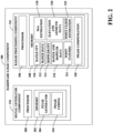
- the described techniques employ a common phase code for all transmitters of a single radar system (which may comprise more than one radar sensor) deployed on an autonomous vehicle.
- the phase code is radar-unique or quasi-unique such that different radars of the same type and/or within the same fleet have different phase codes.
- the phase code applied to the transmitted signal is compensated by a multiplication on the receive side that is common for all transmitters/receivers on the vehicle before the Doppler FFT(s).
- the radar sensor 100 further comprises one or more DACs 108.
- the hardware logic component 106 comprises a signal generator component 110 that prepares radar signals for transmission by way of the transmit antenna 102.
- the signal generator component 110 is configured to control the DAC 108 to cause the DAC 108 to generate an analog radar signal for transmission by the transmit antenna 102.
- the signal generator component 110 generates digital values that, when received by the DAC 108, cause the DAC 108 to output an analog radar signal having various desired signal characteristics.
- the radar sensor 100 is configured as a digitally modulated radar sensor, wherein characteristics of radar signals output by the transmit antenna 102 are digitally controlled by the signal generator component 110 of the hardware logic component 106.
- the signal generator component 110 can be configured to control the DAC 108 such that the radar sensor operates as a phase modulated continuous wave (PMCW) radar sensor.
- PMCW phase modulated continuous wave
- the proposed technique can be combined with a phase code multiplexing technique. That is, vehicle radar systems can employ phase code multiplexing and an additional code that is common to all transmitters on the vehicle can be selected from a different dictionary than the one used for multiplexing in order to reduce interference between radars of the same fleet.
- z m denotes the m th output of the Doppler FFT (where m ranges from 1 to M, and where M is the FFT size in the Doppler domain)
- K is the total number of chirps in the signal
- w ' denotes phase-compensating windowing coefficient(s).
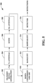
- Fig. 7 illustrates an exemplary methodology relating to mitigating intra-fleet interference between radar systems deployed on autonomous vehicles within a fleet of autonomous vehicles. While the methodology is shown and described as being a series of acts that are performed in a sequence, it is to be understood and appreciated that the methodology is not limited by the order of the sequence. For example, some acts can occur in a different order than is described herein. In addition, an act can occur concurrently with another act. Further, in some instances, not all acts may be required to implement a methodology described herein.
- the acts described herein may be computer-executable instructions that can be implemented by one or more processors and/or stored on a computer-readable medium or media.
- the computer-executable instructions can include a routine, a sub-routine, programs, a thread of execution, and/or the like.
- results of acts of the methodology can be stored in a computer-readable medium, displayed on a display device, and/or the like.
- a methodology 700 is illustrated for mitigating intra fleet interference in accordance with aspects described herein.
- the method begins at 702.
- a phase-shifted radar signal is generated using a unique phase code that is commonly assigned to all transmitters deployed in a radar system on an autonomous vehicle.
- the phase-shifted radar signal is transmitted from transmit antennas.
- a radar return is received at receive antennas.
- phase compensation is performed by multiplying a radar signal received in the radar return by a phase compensation value that is commonly assigned to all receivers deployed on the autonomous vehicle, in order to remove the phase shift.
- an un-shifted processed radar signal is output. The method terminates at 714.
- phase compensation is performed prior to Doppler analysis (Doppler FFT) during signal processing.
- Doppler FFT Doppler analysis
- the unique phase code is assigned statically to the transmitters. This can be done, e.g., during radar system assembly, during flashing of firmware installed in the radar system, during startup of the radar system, etc. Additionally or alternatively, the unique phase code can be assigned periodically to the transmitters by cycling through phase codes in a phase code dictionary. In yet another embodiment, the unique phase code is assigned to the transmitters by selecting a unique phase code per frame based on at least one of external logic and internal logic.
- the external logic can be provided by a remote fleet management system that manages autonomous vehicles in a fleet or via a compass method.
- the phase code can be selected based on compass orientation.
- each of the 360 degrees of the compass can be assigned a different code, and a code can be selected based on the sensor's heading (e.g., North is assigned 0 degrees, South 180 degrees, etc.).
- the only sensors that are assigned the same code are sensors that are facing the same direction and therefore do not interfere with each other.
- more or less than 360 code words can be employed using the compass method, and that the different directions can have any desired degree assignment (e.g., East is assigned 0 degrees, West is assigned 180 degrees, and so on).
- the internal logic is based on radar internal interference detection information whereby if the sensor determines that it is experiencing interference, it selects a new code. For instance, the sensor can analyze received signals/detections using post-processing methods (e.g., outlier detection based on statistics, etc.) to identify interference. In another embodiment, the sensor can implement a listen-before-talk technique, where the sensor monitors the spectrum during transmission downtime to detect other transmitters in the vicinity that might interfere with the sensor.
- post-processing methods e.g., outlier detection based on statistics, etc.
- the method of Fig. 7 can be executed, performed, etc., by any of the systems, components, processors, etc., of Figs. 1-4 , 8 , and/or 9 , and/or any combination(s) thereof.
- the AV 800 additionally comprises a computing system 816 that is in communication with the sensor systems 802-808 and is further in communication with the vehicle propulsion system 810, the braking system 812, and the steering system 814.
- the computing system 816 includes a processor 818 and memory 820 that includes computer-executable instructions that are executed by the processor 818.
- the processor 818 can be or include a graphics processing unit (GPU), a plurality of GPUs, a central processing unit (CPU), a plurality of CPUs, an application-specific integrated circuit (ASIC), a microcontroller, a programmable logic controller (PLC), a field programmable gate array (FPGA), or the like.
- the perception system 822 is configured to identify objects in proximity to the AV 800 that are captured in sensor signals output by the sensor systems 802-808.
- the perception system 822 can be configured to identify the presence of an object in the driving environment of the AV 800 based upon images generated by a camera system included in the sensor systems 804-808.
- the perception system 822 can be configured to determine a presence and position of an object based upon radar data output by the radar sensor system 802.
- the radar sensor system 802 can be or include the radar sensor 80 and/or 300.
- the perception system 822 can be configured to identify a position of an object in the driving environment of the AV 800 based upon the estimated range output by the radar sensor 80 and/or 300.
- the AV 800 can be included in a fleet of AVs that are in communication with a common server computing system.
- the server computing system can control the fleet of AVs such that radar sensor systems of AVs operating in a same driving environment (e.g., within line of sight of one another, or within a threshold distance of one another) employ different pulse sequence carrier frequencies.
- a radar sensor system of a first AV can be controlled so as not to transmit pulse sequences having the same center frequencies as pulse sequences transmitted by a radar sensor system of a second AV at the same time.
- the radar sensor system of the first AV can be controlled to transmit pulse sequences in a different order than a radar sensor system of a second AV.
- the radar sensor system of the first AV can be configured to transmit a set of pulse sequences at four different center frequencies A, B, C, and D in an order A, B, C, D.
- the radar sensor system of the second AV can be configured to transmit pulse sequences using a same set of center frequencies in a frequency order B, A, D, C.
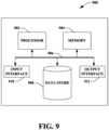
- the computing device 900 may be or include the computing system 816.
- the computing device 900 includes at least one processor 902 that executes instructions that are stored in a memory 904.
- the instructions may be, for instance, instructions for implementing functionality described as being carried out by one or more modules, components, or systems discussed above or instructions for implementing one or more of the methods described above.
- the processor 902 may be a GPU, a plurality of GPUs, a CPU, a plurality of CPUs, a multi-core processor, a combination of the foregoing, etc.
- the processor 902 may access the memory 904 by way of a system bus 906.
- the memory 904 may also store radar data, beamformed radar data, neural network configurations, etc.
- the computing device 900 additionally includes a data store 908 that is accessible by the processor 902 by way of the system bus 906.
- the data store 908 may include executable instructions, radar data, beamformed radar data, embeddings of these data in latent spaces, etc.
- the computing device 900 also includes an input interphase 910 that allows external devices to communicate with the computing device 900. For instance, the input interphase 910 may be used to receive instructions from an external computing device, etc.
- the computing device 900 also includes an output interphase 912 that interphases the computing device 900 with one or more external devices. For example, the computing device 900 may transmit control signals to the vehicle propulsion system 810, the braking system 812, and/or the steering system 814 by way of the output interphase 912.
- the computing device 900 may be a distributed system. Thus, for instance, several devices may be in communication by way of a network connection and may collectively perform tasks described as being performed by the computing device 900.
Landscapes
- Engineering & Computer Science (AREA)
- Radar, Positioning & Navigation (AREA)
- Remote Sensing (AREA)
- Computer Networks & Wireless Communication (AREA)
- Physics & Mathematics (AREA)
- General Physics & Mathematics (AREA)
- Electromagnetism (AREA)
- Radar Systems Or Details Thereof (AREA)
Priority Applications (2)
| Application Number | Priority Date | Filing Date | Title |
|---|---|---|---|
| EP24150374.7A EP4582829A1 (de) | 2024-01-04 | 2024-01-04 | Flotteninterne interferenzabschwächung mit radaruneindeutigen phasencodes |
| US18/406,594 US20250224482A1 (en) | 2024-01-04 | 2024-01-08 | Fleet-internal interference mitigation with radar-unique phase codes |
Applications Claiming Priority (1)
| Application Number | Priority Date | Filing Date | Title |
|---|---|---|---|
| EP24150374.7A EP4582829A1 (de) | 2024-01-04 | 2024-01-04 | Flotteninterne interferenzabschwächung mit radaruneindeutigen phasencodes |
Publications (1)
| Publication Number | Publication Date |
|---|---|
| EP4582829A1 true EP4582829A1 (de) | 2025-07-09 |
Family
ID=89474838
Family Applications (1)
| Application Number | Title | Priority Date | Filing Date |
|---|---|---|---|
| EP24150374.7A Pending EP4582829A1 (de) | 2024-01-04 | 2024-01-04 | Flotteninterne interferenzabschwächung mit radaruneindeutigen phasencodes |
Country Status (2)
| Country | Link |
|---|---|
| US (1) | US20250224482A1 (de) |
| EP (1) | EP4582829A1 (de) |
Citations (5)
| Publication number | Priority date | Publication date | Assignee | Title |
|---|---|---|---|---|
| US20090003412A1 (en) * | 2007-03-02 | 2009-01-01 | Matsushita Electric Industrial Co., Ltd. | Spread spectrum radar apparatus |
| US20180088231A1 (en) * | 2016-09-29 | 2018-03-29 | Panasonic Intellectual Property Management Co., Ltd. | Detection device, detection method, and detection program |
| KR20230001783A (ko) * | 2021-06-29 | 2023-01-05 | 한국항공우주연구원 | 송출 신호 관리 방법, 송출 신호 관리 장치 및 상기 방법을 실행시키기 위하여 기록매체에 저장된 컴퓨터 프로그램 |
| WO2023038765A1 (en) * | 2021-09-09 | 2023-03-16 | Qualcomm Incorporated | Techniques for managing multi-radar co-existence by varying delay and phase |
| US20230288533A1 (en) * | 2022-03-09 | 2023-09-14 | Nxp B.V. | Radar with phase lag compensation |
Family Cites Families (2)
| Publication number | Priority date | Publication date | Assignee | Title |
|---|---|---|---|---|
| DE112017007143B4 (de) * | 2017-03-31 | 2021-05-06 | Mitsubishi Electric Corporation | Radarvorrichtung |
| US12196843B2 (en) * | 2022-05-26 | 2025-01-14 | Waymo Llc | Methods and systems for radar waveform diversity |
-
2024
- 2024-01-04 EP EP24150374.7A patent/EP4582829A1/de active Pending
- 2024-01-08 US US18/406,594 patent/US20250224482A1/en active Pending
Patent Citations (5)
| Publication number | Priority date | Publication date | Assignee | Title |
|---|---|---|---|---|
| US20090003412A1 (en) * | 2007-03-02 | 2009-01-01 | Matsushita Electric Industrial Co., Ltd. | Spread spectrum radar apparatus |
| US20180088231A1 (en) * | 2016-09-29 | 2018-03-29 | Panasonic Intellectual Property Management Co., Ltd. | Detection device, detection method, and detection program |
| KR20230001783A (ko) * | 2021-06-29 | 2023-01-05 | 한국항공우주연구원 | 송출 신호 관리 방법, 송출 신호 관리 장치 및 상기 방법을 실행시키기 위하여 기록매체에 저장된 컴퓨터 프로그램 |
| WO2023038765A1 (en) * | 2021-09-09 | 2023-03-16 | Qualcomm Incorporated | Techniques for managing multi-radar co-existence by varying delay and phase |
| US20230288533A1 (en) * | 2022-03-09 | 2023-09-14 | Nxp B.V. | Radar with phase lag compensation |
Also Published As
| Publication number | Publication date |
|---|---|
| US20250224482A1 (en) | 2025-07-10 |
Similar Documents
| Publication | Publication Date | Title |
|---|---|---|
| CA3111509C (en) | Method and system for pitch-catch scanning of coherent lidar | |
| EP3824314B1 (de) | Vorrichtung und verfahren zur zweistufigen signalverarbeitung in einem radarsystem | |
| CN111521989B (zh) | 用于雷达系统中的超分辨率的深度学习 | |
| JP6637540B2 (ja) | 電子機器、電子機器の制御方法、及び電子機器の制御プログラム | |
| US10914819B2 (en) | Mitigating vibration in a radar system on a moving platform | |
| US10605892B2 (en) | System and method for pseudo randomized chirp scheduling for interference avoidance | |
| US12461224B2 (en) | Velocity disambiguation for radar sensor system | |
| EP4246182B1 (de) | Digital moduliertes multiband-radar | |
| US12196843B2 (en) | Methods and systems for radar waveform diversity | |
| US20250224482A1 (en) | Fleet-internal interference mitigation with radar-unique phase codes | |
| US8188909B2 (en) | Observation signal processing apparatus | |
| US20240353524A1 (en) | Interference mitigation in high resolution radars | |
| US20250110212A1 (en) | Radar free space mapping | |
| EP4492082A1 (de) | Interferenzunterdrückung durch dynamisches falschratenmodell | |
| US12270891B2 (en) | High resolution radar simulation to train vehicle radar system neural network | |
| JP6640269B2 (ja) | 電子機器、電子機器の制御方法、及び電子機器の制御プログラム | |
| US20240069158A1 (en) | Multi chip radar synchronization | |
| EP4506726B1 (de) | Geschwindigkeits- und bereichsdisambiguierung unter verwendung von radarnetzwerken mit wellenformoptimierung | |
| US20250138145A1 (en) | Adc interference cancelation by temporal filter | |
| US20250085386A1 (en) | Radar detector with tracking feedback | |
| JP6953490B2 (ja) | 電子機器、電子機器の制御方法、及び電子機器の制御プログラム | |
| EP4575553A1 (de) | Radarsignalform mit dynamischer dopplerauflösung | |
| US20250052883A1 (en) | Fmcw radar with dynamic waveform model based on ego motion | |
| JP7313525B2 (ja) | 電子機器、電子機器の制御方法、及び電子機器の制御プログラム | |
| Durnakov et al. | Research of noise interference with pseudo-random phase shift keying |
Legal Events
| Date | Code | Title | Description |
|---|---|---|---|
| PUAI | Public reference made under article 153(3) epc to a published international application that has entered the european phase |
Free format text: ORIGINAL CODE: 0009012 |
|
| STAA | Information on the status of an ep patent application or granted ep patent |
Free format text: STATUS: THE APPLICATION HAS BEEN PUBLISHED |
|
| AK | Designated contracting states |
Kind code of ref document: A1 Designated state(s): AL AT BE BG CH CY CZ DE DK EE ES FI FR GB GR HR HU IE IS IT LI LT LU LV MC ME MK MT NL NO PL PT RO RS SE SI SK SM TR |
|
| STAA | Information on the status of an ep patent application or granted ep patent |
Free format text: STATUS: REQUEST FOR EXAMINATION WAS MADE |
|
| 17P | Request for examination filed |
Effective date: 20251209 |
|
| P01 | Opt-out of the competence of the unified patent court (upc) registered |
Free format text: CASE NUMBER: UPC_APP_0013473_4582829/2026 Effective date: 20260422 |