EP4582154A2 - Sportball mit aufhängungssystem - Google Patents
Sportball mit aufhängungssystem Download PDFInfo
- Publication number
- EP4582154A2 EP4582154A2 EP25177505.2A EP25177505A EP4582154A2 EP 4582154 A2 EP4582154 A2 EP 4582154A2 EP 25177505 A EP25177505 A EP 25177505A EP 4582154 A2 EP4582154 A2 EP 4582154A2
- Authority
- EP
- European Patent Office
- Prior art keywords
- hollow shell
- cord
- pit
- cords
- pad
- Prior art date
- Legal status (The legal status is an assumption and is not a legal conclusion. Google has not performed a legal analysis and makes no representation as to the accuracy of the status listed.)
- Pending
Links
Images




Classifications
-
- A—HUMAN NECESSITIES
- A63—SPORTS; GAMES; AMUSEMENTS
- A63B—APPARATUS FOR PHYSICAL TRAINING, GYMNASTICS, SWIMMING, CLIMBING, OR FENCING; BALL GAMES; TRAINING EQUIPMENT
- A63B43/00—Balls with special arrangements
- A63B43/004—Balls with special arrangements electrically conductive, e.g. for automatic arbitration
-
- A—HUMAN NECESSITIES
- A63—SPORTS; GAMES; AMUSEMENTS
- A63B—APPARATUS FOR PHYSICAL TRAINING, GYMNASTICS, SWIMMING, CLIMBING, OR FENCING; BALL GAMES; TRAINING EQUIPMENT
- A63B41/00—Hollow inflatable balls
-
- A—HUMAN NECESSITIES
- A63—SPORTS; GAMES; AMUSEMENTS
- A63B—APPARATUS FOR PHYSICAL TRAINING, GYMNASTICS, SWIMMING, CLIMBING, OR FENCING; BALL GAMES; TRAINING EQUIPMENT
- A63B41/00—Hollow inflatable balls
- A63B41/02—Bladders
-
- A—HUMAN NECESSITIES
- A63—SPORTS; GAMES; AMUSEMENTS
- A63B—APPARATUS FOR PHYSICAL TRAINING, GYMNASTICS, SWIMMING, CLIMBING, OR FENCING; BALL GAMES; TRAINING EQUIPMENT
- A63B43/00—Balls with special arrangements
-
- A—HUMAN NECESSITIES
- A63—SPORTS; GAMES; AMUSEMENTS
- A63B—APPARATUS FOR PHYSICAL TRAINING, GYMNASTICS, SWIMMING, CLIMBING, OR FENCING; BALL GAMES; TRAINING EQUIPMENT
- A63B43/00—Balls with special arrangements
- A63B43/007—Arrangements on balls for connecting lines or cords
-
- A—HUMAN NECESSITIES
- A63—SPORTS; GAMES; AMUSEMENTS
- A63B—APPARATUS FOR PHYSICAL TRAINING, GYMNASTICS, SWIMMING, CLIMBING, OR FENCING; BALL GAMES; TRAINING EQUIPMENT
- A63B45/00—Apparatus or methods for manufacturing balls
-
- A—HUMAN NECESSITIES
- A63—SPORTS; GAMES; AMUSEMENTS
- A63B—APPARATUS FOR PHYSICAL TRAINING, GYMNASTICS, SWIMMING, CLIMBING, OR FENCING; BALL GAMES; TRAINING EQUIPMENT
- A63B71/00—Games or sports accessories not covered in groups A63B1/00 - A63B69/00
- A63B71/06—Indicating or scoring devices for games or players, or for other sports activities
-
- H—ELECTRICITY
- H04—ELECTRIC COMMUNICATION TECHNIQUE
- H04W—WIRELESS COMMUNICATION NETWORKS
- H04W4/00—Services specially adapted for wireless communication networks; Facilities therefor
- H04W4/30—Services specially adapted for particular environments, situations or purposes
- H04W4/38—Services specially adapted for particular environments, situations or purposes for collecting sensor information
-
- A—HUMAN NECESSITIES
- A63—SPORTS; GAMES; AMUSEMENTS
- A63B—APPARATUS FOR PHYSICAL TRAINING, GYMNASTICS, SWIMMING, CLIMBING, OR FENCING; BALL GAMES; TRAINING EQUIPMENT
- A63B24/00—Electric or electronic controls for exercising apparatus of preceding groups; Controlling or monitoring of exercises, sportive games, training or athletic performances
- A63B24/0021—Tracking a path or terminating locations
- A63B2024/0028—Tracking the path of an object, e.g. a ball inside a soccer pitch
-
- A—HUMAN NECESSITIES
- A63—SPORTS; GAMES; AMUSEMENTS
- A63B—APPARATUS FOR PHYSICAL TRAINING, GYMNASTICS, SWIMMING, CLIMBING, OR FENCING; BALL GAMES; TRAINING EQUIPMENT
- A63B39/00—Hollow non-inflatable balls, i.e. having no valves
- A63B2039/006—Hollow non-inflatable balls, i.e. having no valves pressurised
-
- A—HUMAN NECESSITIES
- A63—SPORTS; GAMES; AMUSEMENTS
- A63B—APPARATUS FOR PHYSICAL TRAINING, GYMNASTICS, SWIMMING, CLIMBING, OR FENCING; BALL GAMES; TRAINING EQUIPMENT
- A63B2102/00—Application of clubs, bats, rackets or the like to the sporting activity ; particular sports involving the use of balls and clubs, bats, rackets, or the like
- A63B2102/02—Tennis
-
- A—HUMAN NECESSITIES
- A63—SPORTS; GAMES; AMUSEMENTS
- A63B—APPARATUS FOR PHYSICAL TRAINING, GYMNASTICS, SWIMMING, CLIMBING, OR FENCING; BALL GAMES; TRAINING EQUIPMENT
- A63B2209/00—Characteristics of used materials
- A63B2209/02—Characteristics of used materials with reinforcing fibres, e.g. carbon, polyamide fibres
- A63B2209/023—Long, oriented fibres, e.g. wound filaments, woven fabrics, mats
-
- A—HUMAN NECESSITIES
- A63—SPORTS; GAMES; AMUSEMENTS
- A63B—APPARATUS FOR PHYSICAL TRAINING, GYMNASTICS, SWIMMING, CLIMBING, OR FENCING; BALL GAMES; TRAINING EQUIPMENT
- A63B2220/00—Measuring of physical parameters relating to sporting activity
- A63B2220/10—Positions
-
- A—HUMAN NECESSITIES
- A63—SPORTS; GAMES; AMUSEMENTS
- A63B—APPARATUS FOR PHYSICAL TRAINING, GYMNASTICS, SWIMMING, CLIMBING, OR FENCING; BALL GAMES; TRAINING EQUIPMENT
- A63B2220/00—Measuring of physical parameters relating to sporting activity
- A63B2220/80—Special sensors, transducers or devices therefor
- A63B2220/83—Special sensors, transducers or devices therefor characterised by the position of the sensor
- A63B2220/833—Sensors arranged on the exercise apparatus or sports implement
-
- A—HUMAN NECESSITIES
- A63—SPORTS; GAMES; AMUSEMENTS
- A63B—APPARATUS FOR PHYSICAL TRAINING, GYMNASTICS, SWIMMING, CLIMBING, OR FENCING; BALL GAMES; TRAINING EQUIPMENT
- A63B2225/00—Miscellaneous features of sport apparatus, devices or equipment
- A63B2225/50—Wireless data transmission, e.g. by radio transmitters or telemetry
-
- A—HUMAN NECESSITIES
- A63—SPORTS; GAMES; AMUSEMENTS
- A63B—APPARATUS FOR PHYSICAL TRAINING, GYMNASTICS, SWIMMING, CLIMBING, OR FENCING; BALL GAMES; TRAINING EQUIPMENT
- A63B2243/00—Specific ball sports not provided for in A63B2102/00 - A63B2102/38
- A63B2243/0025—Football
-
- A—HUMAN NECESSITIES
- A63—SPORTS; GAMES; AMUSEMENTS
- A63B—APPARATUS FOR PHYSICAL TRAINING, GYMNASTICS, SWIMMING, CLIMBING, OR FENCING; BALL GAMES; TRAINING EQUIPMENT
- A63B2243/00—Specific ball sports not provided for in A63B2102/00 - A63B2102/38
- A63B2243/0037—Basketball
-
- A—HUMAN NECESSITIES
- A63—SPORTS; GAMES; AMUSEMENTS
- A63B—APPARATUS FOR PHYSICAL TRAINING, GYMNASTICS, SWIMMING, CLIMBING, OR FENCING; BALL GAMES; TRAINING EQUIPMENT
- A63B2243/00—Specific ball sports not provided for in A63B2102/00 - A63B2102/38
- A63B2243/0066—Rugby; American football
-
- A—HUMAN NECESSITIES
- A63—SPORTS; GAMES; AMUSEMENTS
- A63B—APPARATUS FOR PHYSICAL TRAINING, GYMNASTICS, SWIMMING, CLIMBING, OR FENCING; BALL GAMES; TRAINING EQUIPMENT
- A63B2243/00—Specific ball sports not provided for in A63B2102/00 - A63B2102/38
- A63B2243/0095—Volleyball
-
- A—HUMAN NECESSITIES
- A63—SPORTS; GAMES; AMUSEMENTS
- A63B—APPARATUS FOR PHYSICAL TRAINING, GYMNASTICS, SWIMMING, CLIMBING, OR FENCING; BALL GAMES; TRAINING EQUIPMENT
- A63B24/00—Electric or electronic controls for exercising apparatus of preceding groups; Controlling or monitoring of exercises, sportive games, training or athletic performances
- A63B24/0062—Monitoring athletic performances, e.g. for determining the work of a user on an exercise apparatus, the completed jogging or cycling distance
-
- A—HUMAN NECESSITIES
- A63—SPORTS; GAMES; AMUSEMENTS
- A63B—APPARATUS FOR PHYSICAL TRAINING, GYMNASTICS, SWIMMING, CLIMBING, OR FENCING; BALL GAMES; TRAINING EQUIPMENT
- A63B69/00—Training appliances or apparatus for special sports
- A63B69/002—Training appliances or apparatus for special sports for football
-
- A—HUMAN NECESSITIES
- A63—SPORTS; GAMES; AMUSEMENTS
- A63B—APPARATUS FOR PHYSICAL TRAINING, GYMNASTICS, SWIMMING, CLIMBING, OR FENCING; BALL GAMES; TRAINING EQUIPMENT
- A63B71/00—Games or sports accessories not covered in groups A63B1/00 - A63B69/00
- A63B71/06—Indicating or scoring devices for games or players, or for other sports activities
- A63B71/0605—Decision makers and devices using detection means facilitating arbitration
Definitions
- the present disclosure relates to a sports ball, in particular a football or soccer ball.
- Sports balls such as soccer balls, used in sporting activities may comprise a hollow shell, including bladder.
- the hollow shell may be empty or may comprise one or more electronic devices to provide information regarding various parameters of the sporting activity.
- Information may comprise the position of the ball at any time during the sporting activity, parameters of the ball and/or the performance of individual players. The information may be desirable to individuals watching the game, referees, and other persons monitoring the game for compliance with the rules, or trainers or the athlete for performance and medical monitoring.
- the knot of each of the plurality of cords according to the thirteenth embodiment (13) is disposed in the socket of one of the plurality of grooves.
- the hollow shell according to any one of embodiments (1)-(21) comprises an inflatable bladder.
- each cord according to the thirty-seventh embodiment (37) is bonded to the pad at each respective spaced apart location.
- the suspension systems described herein can fix the electronic devices in the center of the ball such that an electronic device is consistently positioned at the intersection of central longitudinal and lateral axes of the ball.
- Electronic devices can be fixed in this way as the ball experiences deformations and spin, limiting or preventing operational interferences and any effects on accuracy of information gathered by the electronic devices.
- the suspension systems can also reliably limit or prevent damage of the electronic devices as the electronic devices are fixed in the center of the ball.
- a method of making the sports ball according to embodiments described herein may comprise coupling one or more cords to the pit and to the hollow shell at spaced apart locations as described herein.
- the spaced part locations may be equidistant over a surface area of the hollow shell.
- the cord(s) may be coupled to the hollow shell by bonding opposing ends of the cord to the hollow shell at two spaced apart locations.
- the cord(s) may be coupled to the hollow shell by bonding opposing ends of the cord to separate pads, which are bonded to the hollow shell at spaced apart locations.
- the suspension system and pit may be manufactured without requiring the hollow shell to be turned inside out.
- the cords according to embodiments described herein may comprise a first end coupled to the hollow shell at a first location, a center portion coupled to the pit, and a second end opposite the first end and coupled to the hollow shell at a second location. Accordingly, one cord may thread through the ball from the hollow shell, to the pit, and back to the hollow shell.
- the two locations where the cord is coupled to the hollow shell may be referred to as anchor points for suspending the pit.
- the center portion of the cord may be coupled to the pit using one or more of the following fastening mechanisms that fixedly couple the cord to the pit.
- the fastening mechanism(s) may couple the cord to the pit such that the pit is maintained in its desired position within the hollow shell during use of the ball.
- the center portion may be coupled to the pit with an adhesive.
- the center portion of the cord may be coupled to the pit by looping through a groove in the pit. In some embodiments, the cord may be coupled to the pit by fixing the center portion of the cord within a groove in the pit. In some embodiments, the center portion of the cord may comprise a mass fixed within a groove in the pit. In some embodiments, the mass may be a knot in the cord, a separate piece bonded to the center portion of the cord, or a combination thereof.
- the cord may be coupled to the pit by fixing the center portion of the cord within a socket in the pit.
- the center portion of the cord may comprise a mass fixed within a socket in the pit.
- the mass may be a knot in the cord, a separate piece bonded to the center portion of the cord, or a combination of both.
- the socket may comprise walls that fix the mass in place.
- the cord may be coupled to the pit by looping through a groove in the pit and fixing the center portion of the cord within a socket of the groove.
- the groove may comprise first and second ends connected by the socket.
- the socket disposed between the first end and the second end, may be formed on an exterior surface of the pit and configured to receive the mass at the center portion of the cord.
- the cord may extend from the socket and respectively exit the pit at the first end and second end of the groove.
- the knot may be tightened, for example by a pneumatic system, before coupling the cord to the pit. Tightening the knot prior to mounting can ensure that the knot will not tighten during the use of the ball, thus causing the cord to loosen.
- the first and second ends of the cord may be coupled to the hollow shell using one or more of the following fastening mechanisms that fixedly couple the first and second ends to first and second locations, respectively, on the hollow shell.
- the first and second ends of the cords may be coupled to the hollow shell with an adhesive. In some embodiments, the first and second ends of the cords may be coupled to the hollow shell with a pad bonded to the hollow shell with an adhesive. In some embodiments, the first and second ends of the cords may be directly bonded to the hollow shell. For example, the first and second ends of the cords may be directly heat bonded to the hollow shell.
- the first and second ends of the cords may be coupled to the hollow shell by sandwiching each of the first and second ends between two pad layers of a pad.
- a pad comprising the pad layers may be bonded to the hollow shell, thereby coupling the first and second ends to the hollow shell.
- the pad may be bonded to an exterior surface of the hollow shell.
- the first and second ends may be glued to the pad layers.
- the first and second ends may be flattened onto a pad layer such that each of the first and second ends spans all or a portion of the entire effective diameter of the pad layer.
- the first and second ends may be frayed to form a flattened portion for attaching to the pad. In such embodiments, the frayed ends may increase the effective diameter of the cords to increase the surface area for fixing cords to pads.
- Providing one or more continuous cords as described herein can both simplify the pit suspension and reduce manufacturing costs. For example, the number of cords needed to suspend the pit within the hollow shell can be minimized, thus minimizing material cost.
- the one or more cords as described herein can minimize the weight added to the ball by the suspension system.
- the cords described herein may be paracords that provide high strength and slight elasticity, with less weight, further limiting the added weight from including the suspension system.
- the pit may be a center mass devoid of any electronic components. In such embodiments, the pit may serve to add weight to the sports ball without contributing any electronic features.
- the pit may comprise one or more electronic devices.
- the pit may comprise a sensor casing that comprises one or more electronic devices to provide information regarding various parameters of the athletic activity.
- the electronic device may comprise a battery, a wireless transmitter, one or more sensors, or any combination thereof.
- the sensor(s) may provide information regarding various parameters of the sporting activity.
- the information may comprise the position of the ball at any time during the sporting activity, parameters of the ball, such as an acceleration, a velocity, and a position of the ball, and/or the performance of individual players.
- the transmitter may facilitate communicating the sensed information to one or more stakeholders.
- the pit and electronic devices may be assembled separately with the cords.
- the cords and hollow shell may be assembled separately from the pit and electronic devices.
- one or more first fixtures may be used to cut a cord to a proper length.
- First and second cord lines may extend along the first fixtures and be fixed to the first fixtures to cut the cord. These first fixtures may be removed from the ball after assembly, such as after cutting the cord.
- second fixtures may be used to bond first end and second end of the cord to one or more layers of patches.
- a thin plate, that supports the cord ends on patches bonded to the exterior surface of the hollow shell may be arranged at an end of one of the second fixtures.
- the plate may be bonded to a patch. In some embodiments, the plate may form a layer of a patch.
- the cord ends may be threaded through openings in the plates. Accordingly, the plates may extend around the cord ends. In some embodiments, the plate partially extends around the cord ends.
- the second fixture may anchor a plate such that a cord end may be threaded through the plate. The cord ends may extend from openings in the plates and onto the plates such that the lengths of the ends are fixed. In this way, the final length of extension of the cords from the pit may be fixed.
- the cord ends are frayed. The frayed ends may be folded outwards and bonded to the plates.
- the plates may have any suitable shape, for example a circular shape, a rectangular shape, or triangular shape. Additionally, in some embodiments, the plates may not extend along the full perimeter around the opening of the plate.
- the patch, hollow shell, and plate may comprise the same or different material.
- the patch may be the same material as the hollow shell.
- the patch and the hollow shell may comprise a material of the same material class (e.g., rubber materials).
- the patch and plate may form a pad such that the plate is a first pad layer and the patch is a second pad layer.
- An opening may be formed in the hollow shell to allow the cord to extend through such that the cord may be bonded to the first pad layer and/or the second pad layer.
- the first pad layer and/or the second pad layer may comprise a larger effective diameter in comparison to the opening to allow an inner side of the first pad layer and/or the second pad layer to bond to the hollow shell.
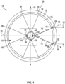
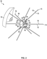
- FIG. 1 shows a ball 100 comprising a suspension system 110 for suspending a pit 140 within a hollow shell 130 according to some embodiments.
- Ball 100 may be used in sporting activities, such as soccer, basketball, volleyball, rugby, football, tennis, etc.
- ball 100 comprises an outer layer 120 and hollow shell 130.
- hollow shell 130 may comprise a bladder.
- hollow shell 130 may comprise an inflatable bladder.
- hollow shell 130 may be arranged within outer layer 120.
- outer layer 120 may comprise a plurality of panels (e.g., pentagons or hexagons), which are adhered, sewn, or welded together.
- a carcass may be arranged between outer layer 120 and hollow shell 130 to reinforce hollow shell 130.
- carcass may help prevent damage to hollow shell 130 from external shock, improve the form stability of ball 100, or both.
- the carcass may comprise a band or the like being wound around the bladder.
- the carcass may be adhered to hollow shell 130.
- Hollow shell 130 may comprise an exterior surface 132 and an interior 134.
- exterior surface 132 may comprise a suitable coating, e.g., a transparent film, such that hollow shell 130 itself may be used as a ball without needing a separate outer layer, such as outer layer 120.
- Interior 134 may be a hollow portion, or void, in hollow shell 130.
- Another exemplary construction of a soccer ball is disclosed in U.S. Pat. No. 6,306,054 , the entire disclosure of which is hereby incorporated by reference herein.
- Suspension system 110 within hollow shell 130 may serve to locate, support, cushion, and restore position of one or more pits 140 disposed within hollow shell 130, i.e., within interior 134.
- Pit 140 may be suspended within hollow shell 130 by one or more cords 170.
- cords 170 In some embodiments, pit 140 may be suspended within hollow shell 130 by a plurality of cords 170.
- Each of the plurality of cords 170 may comprise a first end 172, a center portion 180, and a second end 184.
- First end 172 and second end 184 may be opposing proximal portions of each cord 170.
- Center portion 180 may comprise the portion of cord 170 at the center of the length of cord 170, the length measured from the first end 172 to second end 184.
- center portion 180 of cord 170 may comprise the portion of cord located at the center point of the length of cord 170.
- First end 172 of each respective cord 170 may be coupled to hollow shell 130 at a first location 106.
- Second end 184 of each respective cord 170 may be coupled to hollow shell 130 at a second location 108 spaced apart from the first location.
- First locations 106 and second locations 108 where each cord 170 is coupled to hollow shell 130 may be referred to as anchor points for suspending pit 140.
- first locations 106 and second locations 108 may be locations on exterior surface 132 of hollow shell 130.
- the center portion 180 of each of the plurality of cords may be coupled to hollow shell 130 at a respective coupling 141.
- Each coupling 141 may utilize one or more of the following fastening mechanisms to fixedly couple center portion 180 of cord 170 to pit 140.
- the fastening mechanism may comprise an adhesive. In some embodiments, the fastening mechanism may comprise an opening in pit 140. In some embodiments, the fastening mechanism may comprise a void formed in pit 140 by overmolding a portion of the pit 140 on the center portion 180 of the cord 170. In some embodiments, the fastening mechanism may comprise a groove, for example groove 146. In some embodiments, the fastening mechanism may comprise a socket, for example socket 150. In some embodiments, the fastening mechanism may comprise a combination of a groove and a socket, for example groove 146 comprising socket 150. That said, in some embodiments, the fastening mechanism may comprise a groove without a socket, or a socket without a groove. In some embodiments, the fastening mechanism may comprise a clamp or similar frictional fastening device. In some embodiments, the fastening mechanism may comprise a hook.
- exterior surface 142 of pit 140 may comprise a fastening mechanism through which cord 170 may be looped.
- the fastening mechanisms may be U-shaped brackets having ends secured to pit 140.
- a crimp e.g., a metal crimp
- an overmolded portion may be formed around cord 170 adjacent the fastening mechanisms to positionally lock cord 170.
- a C-clip may be secured around cord 170 adjacent the fastening mechanisms to positionally lock cord 170.
- a heat shrink tube may be secured around cord 170 adjacent the fastening mechanisms to positionally lock cord 170.
- each cord 170 may be coupled to pit 140 in the same way, i.e., using the same type of fastening mechanism(s).
- different cords 170 may be coupled to pit 140 in different ways, i.e., using different types of fastening mechanisms.
- one cord 170 may be looped through a groove on exterior surface 142 while another cord 170 may be looped through a structurally distinct groove on exterior surface 142.
- one cord 170 may be bonded to exterior surface 142 while another cord 170 may be looped through a groove on exterior surface 142.
- center portion 180 of each of the plurality of cords 170 may be looped through pit 140 to fixedly couple center portions 180 at respective couplings 141.
- each of the plurality of cords 170 may be looped through one or more features on exterior surface 142 of pit 140.
- each of the plurality of cords 170 may be looped through one or more features on an interior surface 143 of pit 140.
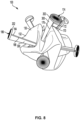
- the one or more features on exterior surface 142 may comprise a groove 146.
- pit 140 may comprise a plurality of grooves 146.
- each of the plurality of grooves 146 may comprise one or more curves.
- each of the plurality of grooves 147 may comprise a series of curves through which cord 170 is looped.
- each of the plurality of grooves 147 may comprise at least one of a first curve 148, a socket 150, and a second curve 152.
- groove 146 may partially extend from exterior surface 142 to an interior 144 of pit 140.
- groove 146 may entirely extend from exterior surface 142 to an interior 144 of pit 140.
- Interior 144 may be a hollow portion, or void, in pit 140.
- groove 146 may extend at least partially from interior surface 143 of pit 140 towards an exterior of pit 140.
- at least one of the plurality of cords 170 may be looped through one or more features on interior surface 143 of pit 140. Further, in such embodiments, cord 170 may be threaded through openings in pit 140 to loop through the one or more features on interior surface 143 of pit 140.
- groove 146 may comprise socket 150 on exterior surface 142.
- each of the plurality of grooves 146 may comprise first curve 148, second curve 152, and socket 150 connecting first curve 148 and second curve 152.
- first curve 148 and second curve 152 may be openings extending from exterior surface 142 to interior 144.
- first curve 148, socket 150, and second curve 152 may form an S-shaped groove 146.
- first curve 148, socket 150, and second curve 152 may form a hook-shaped groove 146.
- pit 140 may comprise one or more S-shaped grooves 146.
- pit 140 may comprise one or more hook-shaped grooves 146.
- pit 140 may comprise one or more S-shaped grooves 146 and one or more hook-shaped grooves 146.
- socket 150 disposed between first curve 148 and second curve 152 may receive center portion 180 of cord 170.
- socket 150 may be a recess on exterior surface 142.
- socket 150 may be a channel connecting first curve 148 and second curve 152.
- socket 150 may be an enclosed channel.
- socket 150 may be an enclosed channel formed by overmolding pit 140 on center portion 180 of cord 160.
- groove 146 may comprise socket 150 located on interior surface 143 of pit 140.
- socket 150 may be a recess on interior surface 143 of pit 140.
- cord 170 may be threaded through openings in pit 140 to loop through the socket 150 on interior surface 143 of pit 140.
- socket 150 may comprise a recessed portion 153 and one or more walls 151.
- walls 151 may form a sidewall of recessed portion 153.
- recessed portion 153 may be surrounded by walls 151.
- walls 151 may retain center portion 180 to limit or prevent movement of center portion 180 of cord 170 relative to pit 140.
- center portion 180 of each of the plurality of cords 170 may be fixed in recessed portion 153 of a socket 150.
- center portion 180 of each of the plurality of cords 170 may comprise a widened mass 181 such that center portion 180 is fixed in socket 150 by an interference or friction fit between mass 181 and socket 150.
- widened mass 181 of center portion 180 of each of the plurality of cords 170 may comprise a knot 182.
- knot 182 may be arranged in one of the plurality of grooves 146.
- knot 182 may be arranged in one of the plurality of sockets 150 of one of the plurality of grooves 146 located on exterior surface 142 of pit 140.
- widened mass 181 of center portion 180 each of the plurality of cords 170 may comprise a separate piece of material attached to center portion 180.
- mass 181 may be a piece of plastic or metal molded onto center portion 180 of cord 170.
- the separate piece may be arranged in one of the plurality of grooves 146.
- the separate piece may be arranged in one of the plurality of sockets 150 of one of the plurality of grooves 146 located on exterior surface 142 of pit 140.
- groove 146 may comprise one or more features to facilitate fixing center portion 180 of cord 170.
- groove 146 may comprise barbs.
- first curve 148 and second curve 152 may comprise barbs to anchor cord 170 in groove 146.
- groove 146 may comprise one or more hooks.
- center portion 180 may loop onto the hook(s) in groove 146 to facilitate interlocking center portion 180 to pit 140.
- groove 146 may comprise a plurality of curves through which center portion 180 can be wound to fixedly couple center portion 180 to pit 140.
- center portion 180 of each of the plurality of cords 170 may be looped through one of the plurality of grooves 146 located on exterior surface 142 of pit 140.
- cord 170 may extend into pit 140 from socket 150 and respectively exit pit 140 at first curve 148 and second curve 152 of groove 146.
- Opposing portions of the cord 170 may then extend to hollow shell 130 (for example, along axes 178 and 190 as shown in FIG. 1 ) to a first location 106 and a second location 108, respectively. In this way, continuous cord 170 may thread through ball 100 from hollow shell 130, to pit 140, and back to hollow shell 130.
- a plurality of continuous cords 170 may thread through ball 100 from hollow shell 130, to one of a plurality of grooves 146 on pit 140, and back to hollow shell 130.
- each of the plurality of cords 170 may extend to a respective first location 106 on hollow shell 130 from first curve 148 of one of the plurality of grooves 146.
- a mass of center portion 180 (e.g., knot 182) of each of the plurality of cords 170 may be arranged in one of the plurality of sockets 150 of one of the plurality of grooves 146.
- each of the plurality of cords 170 may extend to a respective second location 108 on hollow shell 130 from second curve 152 of one of the plurality of grooves 146.
- pit 140 may provide a central mass to ball 100. In some embodiments, pit 140 may comprise a mass of less than or equal to 50 grams. In some embodiments, pit 140 may comprise a mass of less than or equal to 30 grams. In some embodiments, pit 140 may comprise a mass between 22 grams and 26 grams, such as 24 grams. In some embodiments, ball 100 may comprise a mass between 410 grams and 450 grams.
- pit 140 is simply a center mass with no other function. In other embodiments, pit 140 may comprise one or more functional components. For example, as shown in FIG. 4 , pit 140 may comprise one or more electronic devices 154. In some embodiments, electronic device 154 may comprise a battery 156 and a wireless transmitter 158. In some embodiments, electronic device 154 may comprise one or more sensors 160. Sensors 160 may be powered by battery 156. Sensors 160 may collect information regarding various parameters of a sporting activity. In some embodiments, the information may comprise the position of the ball 100 at any time during the sporting activity, parameters of ball 100, such as a velocity and a position of ball 100, and/or the performance of individual players.
- pit 140 may protect electronic device 154 from damage.
- pit 140 may comprise a stiff material, such as a lightweight but rigid plastic material, to provide protection for the sensitive components of electronic device 154.
- Suitable plastic materials comprise, for example, thermoplastic urethane (TPU) and acrylnitrile-butadiene-styrole (ABS).
- TPU thermoplastic urethane
- ABS acrylnitrile-butadiene-styrole
- including a carcass may additionally or alternatively facilitate protection of electronic device 154.
- carcass may reinforce a bladder of hollow shell 130, which may increase the stability of electronic device 154 suspended in interior 134 of hollow shell 130.
- interior 134 may be filled by a gas having a particularly high pressure, to limit deformation of ball 100, thereby increasing the stability of electronic device 154 suspended in interior 134.
- Stability of electronic device 154 may be achieved by minimizing or preventing movement of electronic device 154 in interior 134.
- stability of electronic device 154 may be achieved by maintaining pit 140 at the intersection of central longitudinal axis 101 and central lateral axis 103 of hollow shell 130.
- hollow shell 130 may comprise one or more first openings 136.
- First opening(s) 136 may be a hole cut in hollow shell 130 to allow for pit 140 to be disposed in interior 134 of hollow shell 130.
- the term "effective diameter” as used herein is a non-limiting term to describe the size of a component, but this term should not be interpreted as requiring the component to have a circular diameter or shape. Instead, the component may have a non-circular shape, and in such embodiments, the term “effective diameter” is intended to refer to the maximum cross-sectional dimension of the shape. For example, the "effective diameter" of a component having an elliptical cross-sectional shape would be the length of the major axis of the elliptical shape. An "effective radius" is defined as half of an effective diameter.
- hollow shell 130 may comprise one or more second openings 138.
- Second opening(s) 138 may be a hole cut in hollow shell 130 to allow for cords 170 to extend from interior 134 of hollow shell 130 through exterior surface 132.
- second opening 138 may comprise an effective diameter 139.
- the effective diameter of second opening(s) 138 may be smaller than the effective diameter of first opening(s) 136.
- the effective diameter of second opening(s) 138 may be the same as an effective diameter of cords 170.
- two second openings 138 may respectively receive first end 172 and second end 184 of cord 170. In this way, two second openings 138 may coincide with first location 106 and second location 108 where the first and second free ends of each of the plurality of cords 170 are coupled to hollow shell 130. In such embodiments, two second openings 138 may coincide with the anchor points where first ends 172 are coupled to hollow shell 130 and second ends 184 coupled to hollow shell 130.
- second openings 138 may be equidistantly spaced apart on hollow shell 130 by a radial distance 192.
- radial distance 192 between a particular second opening 138 may be spaced apart from its closest radial neighboring second openings 138 by the same radial distance 192.
- each second opening 138 may be equally spaced apart on ball 100.
- distance 192 may be greater than five centimeters or greater than 30 centimeters, depending on the diameter of the ball 100. In some embodiments, distance 192 may be equal to distance 109.
- Cords 170 may be coupled to hollow shell 130 at first locations 106 and second locations 108 by coupling first end 172 of a respective cord 170 at a first location 106 and coupling second end 184 of the respective cord 170 at a second location 108.
- First and second ends 172/184 of cord 170 may be coupled to first location 106 and second location 108 such that the first and second ends are fixed at first location 106 and second location 108 respectively.
- first location 106 and second location 108 may be anchor points for suspending pit 140.
- Ends 172 and 184 of cords 170 may be coupled to hollow shell 130 using one or more of the following mechanisms that fixedly couple the first and second ends 172/184 to first and second locations 106/108, respectively, on hollow shell 130.
- ends 172 and 184 of cord 170 may be coupled to hollow shell 130 with an adhesive.
- ends 172 and 184 of cord 170 may be coupled to hollow shell 130 by directly bonding ends 172/184 to hollow shell 130, for example by heat bonding ends 172/184 to hollow shell 130.
- ends 172/184 of cord 170 may be coupled to hollow shell 130 by adhesively bonding (gluing) first end 172 and second end 184 to one or more layers of one or more pads 200.
- ends 172/184 of cord 170 may be coupled to hollow shell 130 with by stitching ends 172/184 to hollow shell 130. In some embodiments, ends 172/184 of cord 170 may be coupled to hollow shell 130 by clamping ends 172/184 of cord 170 to hollow shell 130. In some embodiments, first end 172 and second end 184 may be coupled to hollow shell 130 in the same way. For example, both first end 172 and second end 184 may be adhesively bonded to hollow shell 130. In other embodiments, first end 172 and second end 184 may be coupled to hollow shell 130 in different ways. For example, first end 172 may be stitched to hollow shell 130 while second end 184 is adhesively bonded to hollow shell 130.
- first and second ends 172/184 of cord 170 may be coupled to first location 106 and second location 108, respectively, with separate pads 200 bonded to hollow shell at first location 106 and second location 108.
- a first location 106 may comprise a first pad 200 and a second location 108 may comprise a second pad 200.
- pads 200 may receive cords 170.
- ends 172 and 184 of cords 170 may be sized to fit through openings 206.
- ends 172 and 184 of cords 170 may attach to first pad layers 202.
- ends 172 and 184 of cords 170 may be bent outwardly and bonded to first pad layers 202 after being threaded through openings 206.
- ends 172 and 184 of cords 170 may lay flat on first pad layer 202.
- flat ends 172 and 184 may be adhesively or directly bonded to first pad layers 202.
- flat ends 172 and 184 of cords 170 may be portions of cords 170 molded into a flat shape.
Landscapes
- Health & Medical Sciences (AREA)
- General Health & Medical Sciences (AREA)
- Physical Education & Sports Medicine (AREA)
- Engineering & Computer Science (AREA)
- Computer Networks & Wireless Communication (AREA)
- Signal Processing (AREA)
- Professional, Industrial, Or Sporting Protective Garments (AREA)
- Ropes Or Cables (AREA)
- Braiding, Manufacturing Of Bobbin-Net Or Lace, And Manufacturing Of Nets By Knotting (AREA)
Applications Claiming Priority (2)
| Application Number | Priority Date | Filing Date | Title |
|---|---|---|---|
| US17/856,302 US12121776B2 (en) | 2022-07-01 | 2022-07-01 | Sports ball with suspension system |
| EP23183108.2A EP4299146B1 (de) | 2022-07-01 | 2023-07-03 | Sportball mit aufhängungssystem |
Related Parent Applications (2)
| Application Number | Title | Priority Date | Filing Date |
|---|---|---|---|
| EP23183108.2A Division-Into EP4299146B1 (de) | 2022-07-01 | 2023-07-03 | Sportball mit aufhängungssystem |
| EP23183108.2A Division EP4299146B1 (de) | 2022-07-01 | 2023-07-03 | Sportball mit aufhängungssystem |
Publications (2)
| Publication Number | Publication Date |
|---|---|
| EP4582154A2 true EP4582154A2 (de) | 2025-07-09 |
| EP4582154A3 EP4582154A3 (de) | 2025-08-13 |
Family
ID=87074608
Family Applications (2)
| Application Number | Title | Priority Date | Filing Date |
|---|---|---|---|
| EP23183108.2A Active EP4299146B1 (de) | 2022-07-01 | 2023-07-03 | Sportball mit aufhängungssystem |
| EP25177505.2A Pending EP4582154A3 (de) | 2022-07-01 | 2023-07-03 | Sportball mit aufhängungssystem |
Family Applications Before (1)
| Application Number | Title | Priority Date | Filing Date |
|---|---|---|---|
| EP23183108.2A Active EP4299146B1 (de) | 2022-07-01 | 2023-07-03 | Sportball mit aufhängungssystem |
Country Status (4)
| Country | Link |
|---|---|
| US (2) | US12121776B2 (de) |
| EP (2) | EP4299146B1 (de) |
| JP (1) | JP7622145B2 (de) |
| CN (1) | CN117323635A (de) |
Families Citing this family (1)
| Publication number | Priority date | Publication date | Assignee | Title |
|---|---|---|---|---|
| DE102023207475A1 (de) | 2023-08-03 | 2025-02-06 | Adidas Ag | Sportball mit Aufhängungssystem und Vorrichtung und Verfahren zum Bestimmen des Gleichgewichts eines Sportballs |
Citations (1)
| Publication number | Priority date | Publication date | Assignee | Title |
|---|---|---|---|---|
| US6306054B1 (en) | 1997-07-30 | 2001-10-23 | Adidas International B.V. | Football |
Family Cites Families (25)
| Publication number | Priority date | Publication date | Assignee | Title |
|---|---|---|---|---|
| US996458A (en) * | 1910-10-24 | 1911-06-27 | Ava R Coleman | Game apparatus. |
| US2020484A (en) * | 1933-06-15 | 1935-11-12 | Clinton T Turner | Luminous ball |
| US2864617A (en) * | 1956-03-26 | 1958-12-16 | Seamless Rubber Co | Tether ball |
| US5725445A (en) * | 1997-02-28 | 1998-03-10 | Kennedy; Melvin | Flashing light pneumatic playball |
| US6537125B1 (en) * | 2001-09-04 | 2003-03-25 | Motosko, Iii Stephen J. | Inflatable ball with unpredictable movement |
| US6398616B1 (en) * | 2001-09-04 | 2002-06-04 | Motosko, Iii Stephen J. | Inflatable ball with unpredictable movement |
| DE102004045176B4 (de) | 2004-09-17 | 2011-07-21 | Adidas International Marketing B.V. | Blase |
| US7520830B2 (en) * | 2005-08-11 | 2009-04-21 | Wong Jacob Y | Game ball |
| JP5142366B2 (ja) * | 2007-10-31 | 2013-02-13 | 学校法人東京電機大学 | 遊戯用ボール |
| TW201010760A (en) * | 2008-09-15 | 2010-03-16 | geng-xian Lin | Light-emitting ball |
| DE102008052215B4 (de) * | 2008-10-17 | 2014-12-11 | Cairos Technologies Ag | Ball mit Magnetfeldsensor sowie Verfahren zur Messung |
| DE102008052621A1 (de) * | 2008-10-22 | 2010-04-29 | Fraunhofer-Gesellschaft zur Förderung der angewandten Forschung e.V. | Ovaler Ball, insbesondere Rugbyball |
| US8870690B2 (en) | 2009-11-19 | 2014-10-28 | Wilson Sporting Goods Co. | American-style football including electronics |
| US9849361B2 (en) * | 2014-05-14 | 2017-12-26 | Adidas Ag | Sports ball athletic activity monitoring methods and systems |
| US10523053B2 (en) * | 2014-05-23 | 2019-12-31 | Adidas Ag | Sport ball inductive charging methods and systems |
| CN204352486U (zh) * | 2014-12-29 | 2015-05-27 | 天津展硕科技有限公司 | 使用寿命长且性能好的足球 |
| CN204485230U (zh) | 2015-02-13 | 2015-07-22 | 广西南宁恒健体育设施有限公司 | 内置感应器的球 |
| DE102015204151B4 (de) * | 2015-03-09 | 2025-12-24 | Adidas Ag | Ball, insbesondere Fußball, und Verfahren zur Herstellung eines Balls |
| TWM520923U (zh) * | 2016-01-30 | 2016-05-01 | 和碩聯合科技股份有限公司 | 球體 |
| TWI589334B (zh) * | 2016-02-26 | 2017-07-01 | 和碩聯合科技股份有限公司 | 球體 |
| CN106310615A (zh) | 2016-09-21 | 2017-01-11 | 武汉汇动乐智科技有限公司 | 电子足球球体 |
| EP3287175A1 (de) | 2017-11-14 | 2018-02-28 | Basu Swati | Aufblasbare ballblase mit zwei doppelfunktionsventilen und einer drahtgebundenen wiederaufladbaren elektronischen komponente |
| CN109621339A (zh) * | 2018-12-06 | 2019-04-16 | 左壮 | 篮球投篮模拟球及其制备方法 |
| TWM590470U (zh) | 2019-09-23 | 2020-02-11 | 林宜靜 | 感測器定位結構 |
| CN115068912A (zh) * | 2022-07-18 | 2022-09-20 | 三门峡职业技术学院 | 一种投掷训练用的篮球 |
-
2022
- 2022-07-01 US US17/856,302 patent/US12121776B2/en active Active
-
2023
- 2023-06-30 CN CN202310787633.0A patent/CN117323635A/zh active Pending
- 2023-06-30 JP JP2023108140A patent/JP7622145B2/ja active Active
- 2023-07-03 EP EP23183108.2A patent/EP4299146B1/de active Active
- 2023-07-03 EP EP25177505.2A patent/EP4582154A3/de active Pending
-
2024
- 2024-09-24 US US18/894,585 patent/US20250010145A1/en active Pending
Patent Citations (1)
| Publication number | Priority date | Publication date | Assignee | Title |
|---|---|---|---|---|
| US6306054B1 (en) | 1997-07-30 | 2001-10-23 | Adidas International B.V. | Football |
Also Published As
| Publication number | Publication date |
|---|---|
| EP4299146A2 (de) | 2024-01-03 |
| EP4299146B1 (de) | 2025-11-26 |
| JP7622145B2 (ja) | 2025-01-27 |
| CN117323635A (zh) | 2024-01-02 |
| US12121776B2 (en) | 2024-10-22 |
| US20240001203A1 (en) | 2024-01-04 |
| JP2024007503A (ja) | 2024-01-18 |
| EP4299146A3 (de) | 2024-03-20 |
| US20250010145A1 (en) | 2025-01-09 |
| EP4582154A3 (de) | 2025-08-13 |
Similar Documents
| Publication | Publication Date | Title |
|---|---|---|
| US10737145B2 (en) | Game ball having a reduced moment of inertia | |
| US20250010145A1 (en) | Sports ball with suspension system | |
| ES2606230T3 (es) | Pelota ovalada, en particular de rugby o de fútbol, con emisor | |
| US8512177B2 (en) | American-style football including improved bladder construction for mounting of electronics | |
| US5772545A (en) | Sportsball and manufacturing method thereof | |
| US9211446B2 (en) | Sport ball bladder with a pocket | |
| US20070060454A1 (en) | Portable exercise apparatus | |
| US20080032825A1 (en) | Lacrosse Head Weight Training Device | |
| US5632690A (en) | Golf club shaft protective wrap | |
| WO2025026589A1 (en) | Sports ball with suspension system, and apparatus and method for determining the balance of a sports ball | |
| US20160101326A1 (en) | Sportsball with Weight Control Arrangement | |
| JPH0431088Y2 (de) | ||
| US20250128127A1 (en) | Sports ball having a sensor | |
| US20260069929A1 (en) | Rotationally balanced smart ball | |
| US20260041982A1 (en) | Golf training aid | |
| KR100754118B1 (ko) | 골프티 | |
| GB2345447A (en) | Retaining a golf tee on a retractable cord | |
| CN121794026A (zh) | 具有传感器的运动球 | |
| JPS5852665B2 (ja) | 紐付ゴム球及びその製造法 |
Legal Events
| Date | Code | Title | Description |
|---|---|---|---|
| PUAI | Public reference made under article 153(3) epc to a published international application that has entered the european phase |
Free format text: ORIGINAL CODE: 0009012 |
|
| STAA | Information on the status of an ep patent application or granted ep patent |
Free format text: STATUS: REQUEST FOR EXAMINATION WAS MADE |
|
| REG | Reference to a national code |
Ref country code: DE Ref legal event code: R079 Free format text: PREVIOUS MAIN CLASS: A63B0102020000 Ipc: A63B0041020000 |
|
| 17P | Request for examination filed |
Effective date: 20250520 |
|
| AC | Divisional application: reference to earlier application |
Ref document number: 4299146 Country of ref document: EP Kind code of ref document: P |
|
| AK | Designated contracting states |
Kind code of ref document: A2 Designated state(s): AL AT BE BG CH CY CZ DE DK EE ES FI FR GB GR HR HU IE IS IT LI LT LU LV MC ME MK MT NL NO PL PT RO RS SE SI SK SM TR |
|
| PUAL | Search report despatched |
Free format text: ORIGINAL CODE: 0009013 |
|
| AK | Designated contracting states |
Kind code of ref document: A3 Designated state(s): AL AT BE BG CH CY CZ DE DK EE ES FI FR GB GR HR HU IE IS IT LI LT LU LV MC ME MK MT NL NO PL PT RO RS SE SI SK SM TR |
|
| RIC1 | Information provided on ipc code assigned before grant |
Ipc: A63B 41/02 20060101AFI20250707BHEP Ipc: A63B 24/00 20060101ALI20250707BHEP Ipc: A63B 43/00 20060101ALI20250707BHEP Ipc: A63B 45/00 20060101ALI20250707BHEP Ipc: A63B 69/00 20060101ALI20250707BHEP Ipc: A63B 71/06 20060101ALI20250707BHEP Ipc: A63B 39/00 20060101ALI20250707BHEP Ipc: A63B 102/02 20150101ALI20250707BHEP |