EP4582117A2 - Handbetriebener durchflussregler und system zur verabreichung eines einlaufs umfassend den regler - Google Patents
Handbetriebener durchflussregler und system zur verabreichung eines einlaufs umfassend den regler Download PDFInfo
- Publication number
- EP4582117A2 EP4582117A2 EP25154887.1A EP25154887A EP4582117A2 EP 4582117 A2 EP4582117 A2 EP 4582117A2 EP 25154887 A EP25154887 A EP 25154887A EP 4582117 A2 EP4582117 A2 EP 4582117A2
- Authority
- EP
- European Patent Office
- Prior art keywords
- hand
- regulator
- flow regulator
- enema
- operated
- Prior art date
- Legal status (The legal status is an assumption and is not a legal conclusion. Google has not performed a legal analysis and makes no representation as to the accuracy of the status listed.)
- Pending
Links
Images


Classifications
-
- A—HUMAN NECESSITIES
- A61—MEDICAL OR VETERINARY SCIENCE; HYGIENE
- A61M—DEVICES FOR INTRODUCING MEDIA INTO, OR ONTO, THE BODY; DEVICES FOR TRANSDUCING BODY MEDIA OR FOR TAKING MEDIA FROM THE BODY; DEVICES FOR PRODUCING OR ENDING SLEEP OR STUPOR
- A61M3/00—Medical syringes, e.g. enemata; Irrigators
- A61M3/02—Enemata; Irrigators
- A61M3/0204—Physical characteristics of the irrigation fluid, e.g. conductivity or turbidity
- A61M3/022—Volume; Flow rate
-
- A—HUMAN NECESSITIES
- A61—MEDICAL OR VETERINARY SCIENCE; HYGIENE
- A61M—DEVICES FOR INTRODUCING MEDIA INTO, OR ONTO, THE BODY; DEVICES FOR TRANSDUCING BODY MEDIA OR FOR TAKING MEDIA FROM THE BODY; DEVICES FOR PRODUCING OR ENDING SLEEP OR STUPOR
- A61M3/00—Medical syringes, e.g. enemata; Irrigators
- A61M3/02—Enemata; Irrigators
- A61M3/0233—Enemata; Irrigators characterised by liquid supply means, e.g. from pressurised reservoirs
- A61M3/0254—Enemata; Irrigators characterised by liquid supply means, e.g. from pressurised reservoirs the liquid being pumped
- A61M3/0262—Enemata; Irrigators characterised by liquid supply means, e.g. from pressurised reservoirs the liquid being pumped manually, e.g. by squeezing a bulb
-
- A—HUMAN NECESSITIES
- A61—MEDICAL OR VETERINARY SCIENCE; HYGIENE
- A61M—DEVICES FOR INTRODUCING MEDIA INTO, OR ONTO, THE BODY; DEVICES FOR TRANSDUCING BODY MEDIA OR FOR TAKING MEDIA FROM THE BODY; DEVICES FOR PRODUCING OR ENDING SLEEP OR STUPOR
- A61M2205/00—General characteristics of the apparatus
- A61M2205/33—Controlling, regulating or measuring
- A61M2205/3331—Pressure; Flow
- A61M2205/3334—Measuring or controlling the flow rate
Definitions
- the present invention relates to a flow regulator for use in an enema in combination with an elastomeric bulb pump to inject an enema into an individual, such as an individual in need of intestinal irrigation.
- enema administration is used in its conventional understanding and refers to a procedure in which a liquid, the enema, is injected into the lower bowel by way of the rectum for cleansing the bowel and/or relieving constipation.
- the "enema” can e.g. be water or saline.
- Flow regulators that more or less squeeze the enema supply tubing together to adjust the flow of enema are known in the art.
- Such flow regulators can for example be of the so-called roller type known from intravenous drips.
- roller type known from intravenous drips.
- an enema administration system using just one hand.
- the irrigation catheter is inserted in rectum to allow the enema to flow into the lower bowel via the rectum.
- the elastomeric bulb pump must be operated to inject the required amount of enema.
- Coordination of pumping and adjusting flow rate of enema is a huge challenge for the individual who is placed in a very awkward position when having the irrigation catheter inserted in the rectum.
- a simple flow regulator is known from the applicant's international patent application WO2011023196A1 .
- This known flow regulator comprises a housing and a rotatable cylinder placed inside the housing. The cylinder rotates in the housing by means of a turning knob.
- a turning knob rotates in the housing by means of a turning knob.
- some people find it difficult to operate a turning knob by just one hand in order to properly regulate passage of enema liquid through the flow regulator.
- a flow regulator that can be operated during an enema administration by the same hand that simultaneously operates an elastomeric bulb pump.
- a reliable flow regulator for opening and closing for the flow of enema during an enema administration.
- a flow regulator the operation of which does not require visual sight during operation.
- a flow regulator that has tactile operating means.
- the backflow preventer means serves to avoid backflow from injected enema into the flow regulator or the elastomeric bulb.
- non-return valve may be a suitable backflow preventer means that serves to prevent pressure loss and backflow between pumping cycles of the enema administration.
- the backflow preventer means may accommodate a valve ball or bead, and may have an enema inlet, which faces the exterior regulator body, and an opposite enema outlet, which enema inlet may be traversed by a crossbar configured to prevent the valve ball from being sucked inside the flow regulator when the elastomeric pump is operated.
- the back flow preventer means is tubular to be easily inserted and fitted inside the tubular pump coupling end part.
- the individual need not use a lot of force to squeeze an enema supply tubing, or manipulate a flow regulator by one hand at the same time as pumping the elastomeric bulb pump with the other hand, because the flow regulator is situated a long distance from the elastomeric pump to be reachable by said other hand. It is thus not preferred to have the flow regulator remote from the elastomeric bulb pump because this position would require two-handed operation.
- the flow regulator may advantageously be secured at the downstream end of the elastomeric bulb pump, thus to the tubing at the enema delivery end of the elastomeric bulb pump opposite the enema receiving end of said pump, which enema receiving end is connected to an enema reservoir.
- An especially convenient flow regulator according to the present invention may comprise a main flow body having
- the function principle of the flow regulator resembles the shut off valve function principle of a ball valve, however the flow regulator of the current invention does not utilize a ball but an interior regulator body part that is situated rotatable and substantially coaxially inside the exterior regulator body part.
- a pivotable grip may be provided in operative communication with the interior regulator body part to open and close the enema flow path.
- the pivotable grip can be operated manually from outside the main flow body by means of a pivotable grip in operative communication with the interior regulator body part.
- the pivotable grip moves lengthwise along the main flow regulator body, so that it is minimum in the way during maneuvers, and so that it can be operated while holding e.g. a single operating finger in same location during the entire enema administration.
- the pivotable grip is thus easy accessible and easy to operate from outside the main flow body.
- the interior regulator body part can be turned a selected angle in opposite directions, e.g. 90° or less, such as 88°, 85°, or 83°, around its rotation axis, to allow enema to flow through, or to block the flow of enema.
- the turning of the pivotable grip is stepless, however turning may be stepped.
- the flow regulator may advantageously be secured at the downstream end of the elastomeric bulb pump, thus to the tubing at the enema delivery end of the elastomeric bulb pump opposite the enema receiving end of said pump, which enema receiving end is connected to an enema reservoir.
- the free pump coupling end part may couple to the inspiration end of the elastomeric bulb pump, preferably through a valve member, and the opposite tubular tube coupling end part may serve to couple to the enema tubing that is connected to a reservoir of suitable enema.
- the exterior regulator body part may be configured as an exterior cylinder delimited by an exterior cylinder wall and having an exterior cylinder axis substantially perpendicular to the main flow regulator axis to thereby make the interior regulator body part that is arranged turnable inside the exterior regulator body part easy to couple to the pivotable grip.
- the exterior cylinder may e.g. have a first exterior cylinder end opposite a second exterior cylinder end disposed protruding on each their long sides of the main flow body.
- the exterior cylinder may be disposed substantially at the middle of said main flow body or slightly offset said middle, to be easy accessible at a short distance from the elastomeric pump, such as be accessible by the hand used to operate said elastomeric pump.
- the first flow section and the second flow section may have substantially the same length or different length to provide sufficient coupling length to the respective other component to which the flow regulator is to be coupled, and lengths that provide sufficient distance from the elastomeric pump for the pivotable grip to pivoted without hitting any obstructions.
- the exterior cylinder wall may have a first opening opposite the free pump coupling end and a second opening opposite the free tube coupling end, which first opening extends into the first flow section, and which second opening extends into the second flow section.
- the first opening and the second opening enable flow of enema through the exterior cylinder when the pivotable grip is arranged in open position.
- the interior regulator body part may be an interior cylinder delimited by an interior cylinder wall, and having an interior cylinder axis coaxially aligned with the exterior cylinder axis, to be rotatable inside the exterior cylinder about a common central axis.
- the interior cylinder may have a first interior cylinder end opposite a second interior cylinder end.
- the first interior cylinder end may be in substantially the same plane as the first exterior cylinder end, or close to said first exterior cylinder end.
- the second interior cylinder end may be in substantially the same plane as the second exterior cylinder end, or close to said second exterior cylinder end.
- the interior cylinder advantageously accommodates a diametrically arranged flow pipe through which enema liquid can pass when the interior cylinder is turned appropriately in relation to the exterior cylinder.
- the flow pipe may have a first pipe opening opposite a second pipe opening, which first pipe opening and second pipe opening are located in the interior cylinder wall to obtain a flow path through the interior cylinder and the exterior cylinder.
- first pipe opening and second pipe opening Due to first pipe opening and second pipe opening the flow path through the interior cylinder is alignable with the first opening and the second opening of the exterior cylinder by operating the pivotable grip to pivot the interior cylinder, thereby providing a more or less open enema flow path for performing an enema.
- the interior cylinder is arranged turned away from said alignment and the interior cylinder wall blocks the enema flow path whereby the enema administration is fully stopped or temporarily stopped.
- the first interior cylinder end may have a first cylinder coupling means configured to lock together with a first grip coupling means of the pivotable grip.
- the second interior cylinder end may have a second cylinder coupling means configured to lock together with a second grip coupling means of the pivotable grip.
- pivotable grip may be secured to the interior cylinder at one or both of the interior cylinder ends.
- the interior cylinder may then be arranged inside the exterior cylinder to be pivoted between a fully open flow position in which the first pipe opening is aligned with the first opening in the exterior cylinder wall, and the second pipe opening is aligned with the second opening in the exterior cylinder wall, and a fully closed position in which none of said pipe openings are aligned with any of said first and second openings.
- Any intermediate opening position can be achieved by holding the pivotable grip in a position between the fully open and the fully closed position.
- the pivotable grip may have a U-bend handle part, which U-bend handle part conveniently may have opposite free ends provided with a respective one of the first grip coupling means and the second grip coupling means.
- the U-bend handle part protrudes from the main body part, so that it is easy to contact.
- the U-bend shape has no sharp edges, so that the pivotable grip has a smooth exterior and cannot hurt the surrounding tissue even at a vulnerable site as when close to the anus.
- first grip coupling means and said second grip coupling means can be male coupling means and/or female coupling means.
- first grip coupling means and said second grip coupling means may be configured as coupling means selected from the group comprising snap fittings, hooking means, catch pins, turning holes or combinations thereof.
- the first cylinder coupling means and the second cylinder coupling means may be male coupling means and/or female coupling means adapted to couple to respective complementary first grip coupling means and second grip coupling means in form of female coupling means and/or male coupling means.
- said first cylinder coupling means and second cylinder coupling means can be selected from the group comprising snap fittings, hooking means, keyways or combinations thereof.
- first grip coupling means and the second grip coupling means that engage and interlock with the first cylinder coupling means and the second cylinder coupling means, respectively may be dimensioned so that the first grip coupling means covers the first interior cylinder end and the first exterior cylinder end, and the second grip coupling means covers the second interior cylinder end and the second exterior cylinder end, so that no foreign bodies can enter any of the interior cylinder and the exterior cylinder, or enter the interface between said interior cylinder and exterior cylinder that could obstruct or jam turning the interior cylinder by pivoting the pivotable grip.
- the first exterior cylinder end may have a first pivot stop
- the first interior cylinder end may have a second pivot stop that engages the first pivot stop to restrict a pivot angle of the pivotable grip so that the handle part, such as the U-bend handle part, does not get too close to the main flow body, and is too difficult to grasp and hold onto in order to be operated by the same hand as used to squeeze and relieve pressure on the elastomeric bulb pump.
- the cooperating first pivot stop and second pivot stop serve to restrict the possible pivot angle of the pivotable grip when the enema flow path are to be opened and closed as the need requires.
- the pivot angle of the pivotable grip may correspond to the rotation angle of the interior cylinder between an open position wherein the flow pipe axis is fully aligned with the first opening and the second opening, and a closed position wherein the flow pipe axis is rotated so that the first pipe opening and the second pipe opening are brought fully away from the first opening and the second opening, and is blocked by the exterior cylinder wall.
- the first pivot stop can e.g. be an angular track provided circumferentially on the first exterior cylinder end.
- the second pivot stop can be a protrusion extending from the interior cylinder wall parallel to the exterior cylinder axis along an angular section of the circumference of first interior cylinder end which is shorter than the angular track on the first exterior cylinder end, whereby the protrusion can move from side to side along the angular track.
- the freedom to rotate the interior cylinder in relation to the exterior cylinder is defined by the difference between the angular length of the angular track and the angular length of the protrusion. Said difference is constituted by a sector of a circle which defines the possible pivot angle of the interior cylinder in relation to the exterior cylinder that serves for opening and closing the enema flow path through the flow regulator.
- the protrusion expediently can move from side to side within the angular track but not out of said angular track.
- the flow regulator may be provided with a finger support member that protrudes axially spaced apart from the main flow body along the main flow regulator axis to assist in operation when the pivotable grip is to be operated.
- the finger support member may advantageously serve as a finger abutment or finger grasping element so that the finger(s) that operates the pivotable grip does not slip during turning of said grip.
- the finger support member may be arranged with a gap to the exterior cylinder.
- the finger support member may conveniently be arranged above the exterior regulator body part and have an exterior face having tactile indicator means, whereby the user very easily can verify that the position of the hand-operated flow regulator is correct prior to use.
- the finger support member may advantageously be shaped as a bridge member having opposite bridge ends secured to the tubular pump coupling end part and the tubular tube coupling end part, respectively, thereby extending above the exterior regulator body part so that it does not obstruct turning of the pivotable grip.
- the tactile indicator means may be a row of elevations whereby the user easily can establish the pivot angle of the pivotable grip by feeling the elevations with the fingers.
- the fingers elevations may e.g. be disc-shaped and the discs have gradually reduced sized diameters along the length of the finger support member.
- the elevation having the largest diameter may e.g. be the elevation providing the largest flow through the flow regulator, e.g. a fully open flow path.
- the elevation having the smallest diameter may be the elevation providing no flow through the flow regulator, e.g. a fully closed flow path.
- the invention further relates to an enema administration system comprising an elastomeric bulb pump, an irrigation catheter, and the above-mentioned hand-operated flow regulator of the present invention.
- the free pump coupling end part of the hand-operated flow regulator coupled directly to an inspiration end of the elastomeric bulb pump.
- a tubing is secured to the tube coupling end part and has it opposite end secured to a source of enema, thereby establishing an enema flow path through the flow regulator and the elastomeric bulb pump.
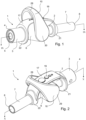
- Figs. 1 and 2 are perspective side views of an exemplary embodiment of a flow regulator 1 with open and closed enema pathway, respectively.
- the flow regulator 1 has a main flow body 2 having a main flow regulator axis A that also is the central axis of the enema flow path.
- Said main flow body 2 has a tubular pump coupling end part 3, in which a back flow preventer in form of a non-return valve 5 is inserted.
- the tubular pump coupling end part 3 has a free pump coupling end 4 and delimits a first flow section F1.
- the tubular pump coupling end part 3 extends via an exterior regulator body part 6 into a tubular tube coupling end part 7 having a free tube coupling end 8 and defining a second flow section F2.
- the flow regulator 1 also comprises an interior regulator body part 9, which is situated substantially coaxially inside the exterior regulator body part 6, and a pivotable grip 10 in operative communication with the interior regulator body part 9 to open and close the enema flow path.
- the pivotable grip 10 is in a position wherein it is pivoted towards the tubular pump coupling end part 3 whereby the enema flow path through the main flow body 2 is closed.
- the enema flow path through the main flow body 2 is open.
- the exterior regulator body part 6 has an exterior cylinder wall 12, and a first exterior cylinder end 13 opposite a second exterior cylinder end 14.
- the exterior regulator body part 6 is further configured as an exterior cylinder 11 having an exterior cylinder axis Y substantially perpendicular to the main flow regulator axis A.
- the exterior cylinder wall 12 has a first opening 15 that extends into the first flow section F1 opposite the free pump coupling end 4, and a second opening 16, which extends into the second flow section F2 opposite the free tube coupling end 8.
- the first opening 15 and the second opening 16 are aligned along the main flow regulator axis A and constitute openings in the enema flow path.
- a finger support member 17 protrudes above the exterior regulator body part 6 and exposes an exterior face 18 having tactile indicator means 19 that enables the individual who performs an enema administration to have a further tactile verification means to verify which direction to move the pivotable grip 10 to open and close the flow regulator 1, as well as to verify whether the flow regulator 1 already is open or closed.
- the finger support member 17 is shaped as a bridge member 20 having opposite bridge ends 21,22 mounted to the tubular pump coupling end part 3 and the tubular tube coupling end part 7, respectively, in a manner so that the bridge member 20 extends above the exterior regulator body part 6 with the opposite bridge ends 21,22 secured to the aforesaid respective coupling parts 3,7.
- the tactile indicator means 19 is in the present embodiment configured as a row of elevation 23 having gradually reduced sizes.
- the finger support member 17 be integral with the main flow body 2, whereby there is no gap between said finger support member 17 and the main flow body 2.
- Alternative tactile indicator means can for example be depressions, rings, ribs or grooves extending crosswise and/or lengthwise the bridge member 20. Some embodiments may not have a finger support member 17 at all.
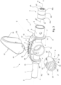
- the second grip coupling means 32 is constituted by two slightly flexible second hooks 32a,32b, as seen in fig. 5 .
- the flexible second hooks 32a,32b are arranged to hook into a second cylinder coupling means 35, seen in fig. 6 , at the second interior cylinder end 27 of the interior cylinder 24.
- the first cylinder coupling means 33 is composed of two diametrically opposite first coupling openings 36a,36b in the interior cylinder wall 25 at the first interior cylinder end 26, for hooking by the flexible first hooks 31a,31b.
- the interior regulator body part 9 is seen from the first interior cylinder end 26 to illustrate that the interior cylinder 24 accommodates a diametrically arranged flow pipe 41 having a first pipe opening 42 opposite a second pipe opening 43 in the interior cylinder wall 25, which second pipe opening 43 becomes aligned with the second opening 16 when the first pipe opening 42 is aligned with the first opening 15 to open the enema flow path by pivoting the pivotable grip 10 towards the tubular tube coupling end part 7, which position is seen in figs. 2 and 10 .
- the pivotable grip 10 By pivoting the pivotable grip 10 in the opposite direction to achieve the position seen in figs. 1 and 9 the flow path is blocked by the interior cylinder wall 25, which are rotated in front of the second opening 16 and the first opening 15 and closes said openings 15,16.
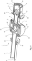
- the valve ball 49 reciprocates during squeezing and relieving pressure on an elastomeric bulb pump 62, which is seen in fig. 11 .
- a negative inspiration pressure builds up thereby arranging the valve ball 49 to close the enema outlet 47 and sucking the enema into the elastomeric bulb pump 62.
- the valve ball 49 returns to the crossbar 48 to allow the enema to be expelled via the enema outlet 47.
- the opposite end of the elastomeric bulb pump 62 has a similar backflow preventer.
- the enema administration system 55 further comprises an enema reservoir 56 in form of a refillable container 57 with a hinged snap lid 58 having vent openings 59 to relieve negative pressure in response to drawing enema from said enema reservoir 56.
- a short length of tubing may extend the distance between the free pump coupling end part of the hand-operated flow regulator and the inspiration end of the elastomeric bulb pump, but said short length of tubing is no longer than both the elastomeric bulb pump and the flow regulator can be held and operated by one same hand.
- the short length of tubing has one end connected to the free pump coupling end part of the hand-operated flow regulator and its opposite end connected to a connection piece adapted to secure to the elastomeric bulb pump.
- the short length of tubing may e.g. have about the same length as the elastomeric bulb pump and the total length of assembled short length of tubing, flow regulator and elastomeric bulb pump may not be longer than the length of a hand.
Landscapes
- Health & Medical Sciences (AREA)
- Heart & Thoracic Surgery (AREA)
- Engineering & Computer Science (AREA)
- Anesthesiology (AREA)
- Biomedical Technology (AREA)
- Hematology (AREA)
- Life Sciences & Earth Sciences (AREA)
- Animal Behavior & Ethology (AREA)
- General Health & Medical Sciences (AREA)
- Public Health (AREA)
- Veterinary Medicine (AREA)
- Fluid Mechanics (AREA)
- Physics & Mathematics (AREA)
- Infusion, Injection, And Reservoir Apparatuses (AREA)
Applications Claiming Priority (3)
| Application Number | Priority Date | Filing Date | Title |
|---|---|---|---|
| DKPA202070824A DK181050B1 (en) | 2020-12-11 | 2020-12-11 | A hand-operated flow regulator and an enema administration system comprising said hand-operated flow regulator |
| EP21830997.9A EP4259237B1 (de) | 2020-12-11 | 2021-12-07 | Handbetriebener durchflussregler und system zur verabreichung eines einlaufs umfassend den regler |
| PCT/EP2021/084512 WO2022122699A1 (en) | 2020-12-11 | 2021-12-07 | Hand-operated flow regulator and enema administration system comprising said regulator |
Related Parent Applications (1)
| Application Number | Title | Priority Date | Filing Date |
|---|---|---|---|
| EP21830997.9A Division EP4259237B1 (de) | 2020-12-11 | 2021-12-07 | Handbetriebener durchflussregler und system zur verabreichung eines einlaufs umfassend den regler |
Publications (2)
| Publication Number | Publication Date |
|---|---|
| EP4582117A2 true EP4582117A2 (de) | 2025-07-09 |
| EP4582117A3 EP4582117A3 (de) | 2025-07-23 |
Family
ID=79025176
Family Applications (2)
| Application Number | Title | Priority Date | Filing Date |
|---|---|---|---|
| EP25154887.1A Pending EP4582117A3 (de) | 2020-12-11 | 2021-12-07 | Handbetriebener durchflussregler und system zur verabreichung eines einlaufs umfassend den regler |
| EP21830997.9A Active EP4259237B1 (de) | 2020-12-11 | 2021-12-07 | Handbetriebener durchflussregler und system zur verabreichung eines einlaufs umfassend den regler |
Family Applications After (1)
| Application Number | Title | Priority Date | Filing Date |
|---|---|---|---|
| EP21830997.9A Active EP4259237B1 (de) | 2020-12-11 | 2021-12-07 | Handbetriebener durchflussregler und system zur verabreichung eines einlaufs umfassend den regler |
Country Status (5)
| Country | Link |
|---|---|
| US (1) | US12036377B2 (de) |
| EP (2) | EP4582117A3 (de) |
| CN (1) | CN116648274A (de) |
| DK (1) | DK181050B1 (de) |
| WO (1) | WO2022122699A1 (de) |
Families Citing this family (1)
| Publication number | Priority date | Publication date | Assignee | Title |
|---|---|---|---|---|
| US20260053607A1 (en) * | 2024-02-12 | 2026-02-26 | Innovative Product Brands, Inc. | Improved handle assembly for a dental or medical tool |
Citations (1)
| Publication number | Priority date | Publication date | Assignee | Title |
|---|---|---|---|---|
| WO2011023196A1 (en) | 2009-08-26 | 2011-03-03 | Mbh-International A/S | An irrigation device and method of using the device |
Family Cites Families (11)
| Publication number | Priority date | Publication date | Assignee | Title |
|---|---|---|---|---|
| GB2166222B (en) | 1984-10-25 | 1989-05-17 | Pharma Plast As | A tap |
| US4966551A (en) | 1988-06-28 | 1990-10-30 | Betush Frank A | Vacuum evacuator for dental debris |
| US5882194A (en) * | 1995-11-27 | 1999-03-16 | Davis; Warren | Illuminated suction tool with a disposable tip |
| FR2845452B1 (fr) | 2002-10-04 | 2005-09-23 | Vygon | Robinet a cle tournante indexable. |
| EP2125072B1 (de) | 2007-03-14 | 2011-08-03 | Coloplast A/S | Schaltvorrichtung und irrigationssystem mit einer solchen vorrichtung |
| US8556873B2 (en) | 2010-01-29 | 2013-10-15 | Mbh-International A/S | Drainage valve and collection bag assembly comprising said valve |
| WO2015117104A1 (en) | 2014-01-31 | 2015-08-06 | Camodo, Llc | Combination suction and irrigation tool |
| US9765899B2 (en) | 2015-11-03 | 2017-09-19 | Stoma Ventures, LLC | Disposable dental valve device |
| US9980790B2 (en) * | 2016-03-28 | 2018-05-29 | Stoma Ventures, LLC | Dental valve device having a disposable turret |
| US20200390961A1 (en) * | 2019-06-13 | 2020-12-17 | Ningbo Albert Novosino Co., Ltd | Anti-reflux leakproof enemator |
| US11661929B1 (en) * | 2019-07-24 | 2023-05-30 | John H. Campbell | Suction valve apparatus and method of using same |
-
2020
- 2020-12-11 DK DKPA202070824A patent/DK181050B1/en active IP Right Grant
-
2021
- 2021-12-07 EP EP25154887.1A patent/EP4582117A3/de active Pending
- 2021-12-07 CN CN202180077361.4A patent/CN116648274A/zh active Pending
- 2021-12-07 EP EP21830997.9A patent/EP4259237B1/de active Active
- 2021-12-07 WO PCT/EP2021/084512 patent/WO2022122699A1/en not_active Ceased
- 2021-12-07 US US18/256,197 patent/US12036377B2/en active Active
Patent Citations (1)
| Publication number | Priority date | Publication date | Assignee | Title |
|---|---|---|---|---|
| WO2011023196A1 (en) | 2009-08-26 | 2011-03-03 | Mbh-International A/S | An irrigation device and method of using the device |
Also Published As
| Publication number | Publication date |
|---|---|
| CN116648274A (zh) | 2023-08-25 |
| DK202070824A1 (en) | 2022-06-17 |
| WO2022122699A1 (en) | 2022-06-16 |
| EP4259237B1 (de) | 2025-02-12 |
| US12036377B2 (en) | 2024-07-16 |
| EP4582117A3 (de) | 2025-07-23 |
| US20240033417A1 (en) | 2024-02-01 |
| EP4259237C0 (de) | 2025-02-12 |
| DK181050B1 (en) | 2022-10-19 |
| EP4259237A1 (de) | 2023-10-18 |
Similar Documents
| Publication | Publication Date | Title |
|---|---|---|
| JP2977612B2 (ja) | 改良された医療用洗浄装置 | |
| US4941872A (en) | Control handle for surgical irrigation and suction device | |
| EP0606449B1 (de) | Medizinische spülvorrichtung sowie verfahren | |
| AU2013273595B2 (en) | Irrigation system comprising dual pumps | |
| ES2123472T3 (es) | Mecanismo de enclavamiento, de enganche y de retencion para una bomba de infusion. | |
| ES2363982T3 (es) | Dispensador con función múltiple. | |
| US9114243B2 (en) | Manual valve actuator for medical fluid delivery set | |
| US20030106559A1 (en) | Manifold | |
| CN114051569B (zh) | 内窥镜空气/水冲洗接头及方法 | |
| US20060025729A1 (en) | Transanal colorectal irrigators | |
| JP2009527337A (ja) | 内視鏡の吸引装置 | |
| WO2011077420A1 (en) | A bubble entrapment device | |
| EP4259237B1 (de) | Handbetriebener durchflussregler und system zur verabreichung eines einlaufs umfassend den regler | |
| BR112021016372A2 (pt) | Válvula para um utensílio de urostomia, e, combinação | |
| DK181589B1 (en) | A hand-operated flow regulator and an enema administration system comprising said hand-operated flow regulator | |
| CN108434545A (zh) | 一种分离式冲洗引流装置 | |
| DK181211B1 (en) | A hand-operated flow regulator and an enema administration system comprising said hand-operated flow regulator | |
| CN211749876U (zh) | 一种腹腔镜下使用的胆道刮匙 | |
| US20060178636A1 (en) | Device for selective access closure inside a catheter | |
| CN112933308B (zh) | 一种导尿管 | |
| CN212067305U (zh) | 一种按压切换式腹腔镜手术吸引器 | |
| US20120078198A1 (en) | Vagina cleaning device | |
| CN112999061A (zh) | 一种多功能鼻窦冲洗装置 | |
| CN210331226U (zh) | 医疗废液吸引管 | |
| JPH0753149B2 (ja) | 内視鏡用送水装置 |
Legal Events
| Date | Code | Title | Description |
|---|---|---|---|
| PUAI | Public reference made under article 153(3) epc to a published international application that has entered the european phase |
Free format text: ORIGINAL CODE: 0009012 |
|
| STAA | Information on the status of an ep patent application or granted ep patent |
Free format text: STATUS: THE APPLICATION HAS BEEN PUBLISHED |
|
| PUAL | Search report despatched |
Free format text: ORIGINAL CODE: 0009013 |
|
| AC | Divisional application: reference to earlier application |
Ref document number: 4259237 Country of ref document: EP Kind code of ref document: P |
|
| AK | Designated contracting states |
Kind code of ref document: A2 Designated state(s): AL AT BE BG CH CY CZ DE DK EE ES FI FR GB GR HR HU IE IS IT LI LT LU LV MC MK MT NL NO PL PT RO RS SE SI SK SM TR |
|
| AK | Designated contracting states |
Kind code of ref document: A3 Designated state(s): AL AT BE BG CH CY CZ DE DK EE ES FI FR GB GR HR HU IE IS IT LI LT LU LV MC MK MT NL NO PL PT RO RS SE SI SK SM TR |
|
| RIC1 | Information provided on ipc code assigned before grant |
Ipc: A61M 3/02 20060101AFI20250616BHEP |
|
| STAA | Information on the status of an ep patent application or granted ep patent |
Free format text: STATUS: REQUEST FOR EXAMINATION WAS MADE |
|
| 17P | Request for examination filed |
Effective date: 20260123 |