EP4582115A2 - Herz-lungen-bypassmaschinensystem - Google Patents
Herz-lungen-bypassmaschinensystem Download PDFInfo
- Publication number
- EP4582115A2 EP4582115A2 EP24213602.6A EP24213602A EP4582115A2 EP 4582115 A2 EP4582115 A2 EP 4582115A2 EP 24213602 A EP24213602 A EP 24213602A EP 4582115 A2 EP4582115 A2 EP 4582115A2
- Authority
- EP
- European Patent Office
- Prior art keywords
- venous
- blood
- controller
- pathway
- hlm
- Prior art date
- Legal status (The legal status is an assumption and is not a legal conclusion. Google has not performed a legal analysis and makes no representation as to the accuracy of the status listed.)
- Pending
Links
Images



Classifications
-
- A—HUMAN NECESSITIES
- A61—MEDICAL OR VETERINARY SCIENCE; HYGIENE
- A61M—DEVICES FOR INTRODUCING MEDIA INTO, OR ONTO, THE BODY; DEVICES FOR TRANSDUCING BODY MEDIA OR FOR TAKING MEDIA FROM THE BODY; DEVICES FOR PRODUCING OR ENDING SLEEP OR STUPOR
- A61M1/00—Suction or pumping devices for medical purposes; Devices for carrying-off, for treatment of, or for carrying-over, body-liquids; Drainage systems
- A61M1/36—Other treatment of blood in a by-pass of the natural circulatory system, e.g. temperature adaptation, irradiation ; Extra-corporeal blood circuits
- A61M1/3621—Extra-corporeal blood circuits
- A61M1/3666—Cardiac or cardiopulmonary bypass, e.g. heart-lung machines
-
- A—HUMAN NECESSITIES
- A61—MEDICAL OR VETERINARY SCIENCE; HYGIENE
- A61M—DEVICES FOR INTRODUCING MEDIA INTO, OR ONTO, THE BODY; DEVICES FOR TRANSDUCING BODY MEDIA OR FOR TAKING MEDIA FROM THE BODY; DEVICES FOR PRODUCING OR ENDING SLEEP OR STUPOR
- A61M1/00—Suction or pumping devices for medical purposes; Devices for carrying-off, for treatment of, or for carrying-over, body-liquids; Drainage systems
- A61M1/36—Other treatment of blood in a by-pass of the natural circulatory system, e.g. temperature adaptation, irradiation ; Extra-corporeal blood circuits
- A61M1/3601—Extra-corporeal circuits in which the blood fluid passes more than once through the treatment unit
- A61M1/3603—Extra-corporeal circuits in which the blood fluid passes more than once through the treatment unit in the same direction
-
- A—HUMAN NECESSITIES
- A61—MEDICAL OR VETERINARY SCIENCE; HYGIENE
- A61M—DEVICES FOR INTRODUCING MEDIA INTO, OR ONTO, THE BODY; DEVICES FOR TRANSDUCING BODY MEDIA OR FOR TAKING MEDIA FROM THE BODY; DEVICES FOR PRODUCING OR ENDING SLEEP OR STUPOR
- A61M1/00—Suction or pumping devices for medical purposes; Devices for carrying-off, for treatment of, or for carrying-over, body-liquids; Drainage systems
- A61M1/36—Other treatment of blood in a by-pass of the natural circulatory system, e.g. temperature adaptation, irradiation ; Extra-corporeal blood circuits
- A61M1/3607—Regulation parameters
-
- A—HUMAN NECESSITIES
- A61—MEDICAL OR VETERINARY SCIENCE; HYGIENE
- A61M—DEVICES FOR INTRODUCING MEDIA INTO, OR ONTO, THE BODY; DEVICES FOR TRANSDUCING BODY MEDIA OR FOR TAKING MEDIA FROM THE BODY; DEVICES FOR PRODUCING OR ENDING SLEEP OR STUPOR
- A61M1/00—Suction or pumping devices for medical purposes; Devices for carrying-off, for treatment of, or for carrying-over, body-liquids; Drainage systems
- A61M1/36—Other treatment of blood in a by-pass of the natural circulatory system, e.g. temperature adaptation, irradiation ; Extra-corporeal blood circuits
- A61M1/3621—Extra-corporeal blood circuits
- A61M1/3622—Extra-corporeal blood circuits with a cassette forming partially or totally the blood circuit
- A61M1/36224—Extra-corporeal blood circuits with a cassette forming partially or totally the blood circuit with sensing means or components thereof
-
- A—HUMAN NECESSITIES
- A61—MEDICAL OR VETERINARY SCIENCE; HYGIENE
- A61M—DEVICES FOR INTRODUCING MEDIA INTO, OR ONTO, THE BODY; DEVICES FOR TRANSDUCING BODY MEDIA OR FOR TAKING MEDIA FROM THE BODY; DEVICES FOR PRODUCING OR ENDING SLEEP OR STUPOR
- A61M1/00—Suction or pumping devices for medical purposes; Devices for carrying-off, for treatment of, or for carrying-over, body-liquids; Drainage systems
- A61M1/36—Other treatment of blood in a by-pass of the natural circulatory system, e.g. temperature adaptation, irradiation ; Extra-corporeal blood circuits
- A61M1/3607—Regulation parameters
- A61M1/3609—Physical characteristics of the blood, e.g. haematocrit, urea
-
- A—HUMAN NECESSITIES
- A61—MEDICAL OR VETERINARY SCIENCE; HYGIENE
- A61M—DEVICES FOR INTRODUCING MEDIA INTO, OR ONTO, THE BODY; DEVICES FOR TRANSDUCING BODY MEDIA OR FOR TAKING MEDIA FROM THE BODY; DEVICES FOR PRODUCING OR ENDING SLEEP OR STUPOR
- A61M1/00—Suction or pumping devices for medical purposes; Devices for carrying-off, for treatment of, or for carrying-over, body-liquids; Drainage systems
- A61M1/36—Other treatment of blood in a by-pass of the natural circulatory system, e.g. temperature adaptation, irradiation ; Extra-corporeal blood circuits
- A61M1/3621—Extra-corporeal blood circuits
- A61M1/3626—Gas bubble detectors
-
- A—HUMAN NECESSITIES
- A61—MEDICAL OR VETERINARY SCIENCE; HYGIENE
- A61M—DEVICES FOR INTRODUCING MEDIA INTO, OR ONTO, THE BODY; DEVICES FOR TRANSDUCING BODY MEDIA OR FOR TAKING MEDIA FROM THE BODY; DEVICES FOR PRODUCING OR ENDING SLEEP OR STUPOR
- A61M2202/00—Special media to be introduced, removed or treated
- A61M2202/0007—Special media to be introduced, removed or treated introduced into the body
-
- A—HUMAN NECESSITIES
- A61—MEDICAL OR VETERINARY SCIENCE; HYGIENE
- A61M—DEVICES FOR INTRODUCING MEDIA INTO, OR ONTO, THE BODY; DEVICES FOR TRANSDUCING BODY MEDIA OR FOR TAKING MEDIA FROM THE BODY; DEVICES FOR PRODUCING OR ENDING SLEEP OR STUPOR
- A61M2202/00—Special media to be introduced, removed or treated
- A61M2202/02—Gases
- A61M2202/0208—Oxygen
-
- A—HUMAN NECESSITIES
- A61—MEDICAL OR VETERINARY SCIENCE; HYGIENE
- A61M—DEVICES FOR INTRODUCING MEDIA INTO, OR ONTO, THE BODY; DEVICES FOR TRANSDUCING BODY MEDIA OR FOR TAKING MEDIA FROM THE BODY; DEVICES FOR PRODUCING OR ENDING SLEEP OR STUPOR
- A61M2205/00—General characteristics of the apparatus
- A61M2205/18—General characteristics of the apparatus with alarm
-
- A—HUMAN NECESSITIES
- A61—MEDICAL OR VETERINARY SCIENCE; HYGIENE
- A61M—DEVICES FOR INTRODUCING MEDIA INTO, OR ONTO, THE BODY; DEVICES FOR TRANSDUCING BODY MEDIA OR FOR TAKING MEDIA FROM THE BODY; DEVICES FOR PRODUCING OR ENDING SLEEP OR STUPOR
- A61M2205/00—General characteristics of the apparatus
- A61M2205/33—Controlling, regulating or measuring
- A61M2205/3303—Using a biosensor
-
- A—HUMAN NECESSITIES
- A61—MEDICAL OR VETERINARY SCIENCE; HYGIENE
- A61M—DEVICES FOR INTRODUCING MEDIA INTO, OR ONTO, THE BODY; DEVICES FOR TRANSDUCING BODY MEDIA OR FOR TAKING MEDIA FROM THE BODY; DEVICES FOR PRODUCING OR ENDING SLEEP OR STUPOR
- A61M2205/00—General characteristics of the apparatus
- A61M2205/33—Controlling, regulating or measuring
- A61M2205/3331—Pressure; Flow
- A61M2205/3334—Measuring or controlling the flow rate
Definitions
- the present disclosure relates to a heart-lung machine (HLM) and methods for manufacturing and/or using a heart-lung machine. More particularly, the present disclosure relates to aspects of a controller and/or configuration(s) for a heart-lung machine and methods for manufacturing and/or using a heart-lung machine.
- HLM heart-lung machine
- HLM heart-lung machine
- An HLM may provide temporary and/or short-term support to a patient during a cardiac procedure. In some procedures, the HLM may permit temporarily stopping the patient's heart.
- An HLM works by removing blood from a patient's body to oxygenate the red blood cells while also removing carbon dioxide. The oxygenated blood is then returned to the patient.
- the controller may include and/or display one or more alarms corresponding to measured values that are outside of predetermined limits.
- Alarms related to set-up conditions may sometimes be considered as false alarms. False alarms may be problematic in that users may ignore them, and then later overlook or ignore real alarms, thereby compromising patient safety. False alarms and/or the expectation of them may also result in missed steps and/or activations during system set-up.
- a heart-lung machine (HLM) system may comprise a controller, and a plurality of venous sensors disposed along a venous pathway, the plurality of venous sensors comprising a venous blood gas sensor.
- the controller Upon activation of the HLM system, the controller is configured to suppress alarms associated with the plurality of venous sensors until blood is detected within the venous pathway by the venous blood gas sensor.
- the HLM system may comprise a plurality of arterial sensors disposed along an arterial pathway.
- the controller upon activation of the HLM system, is configured to suppress alarms associated with the plurality of arterial sensors until blood is detected within the venous pathway by the venous blood gas sensor.
- the HLM system may comprise an oxygenator, a capnograph sensor configured to detect an exhaled carbon dioxide content leaving the oxygenator, and a gas mixture flow sensor configured to detect a flow rate of a compressed air and oxygen gas mixture flowing into the oxygenator.
- the controller is configured to automatically activate the capnograph sensor without alarm limits when a case is started within the controller.
- the controller is configured to automatically activate alarm limits associated with the capnograph sensor upon detection of blood within the venous pathway by the venous blood gas sensor.
- the controller is configured to automatically activate the gas mixture flow sensor and set the flow rate of the compressed air and oxygen gas mixture entering the oxygenator to zero liters per minute when a case is started within the controller.
- the controller upon detection of blood within the venous pathway by the venous blood gas sensor, is configured to automatically check if the flow rate of the compressed air and oxygen gas mixture entering the oxygenator is greater than zero liters per minute and to activate a gas flow notification if the flow rate of the compressed air and oxygen gas mixture entering the oxygenator is not greater than zero liters per minute.
- the controller upon detection of blood within the venous pathway by the venous blood gas sensor, the controller is configured to automatically set the flow rate of the compressed air and oxygen gas mixture to a predetermined value.
- a heart-lung machine (HLM) system may comprise a controller, an oxygenator, a venous pathway configured to transport deoxygenated blood from at least one venous portion of a patient's vasculature to the oxygenator, an arterial pathway configured to transport oxygenated blood from the oxygenator to at least one arterial portion of the patient's vasculature, and a plurality of venous sensors disposed along the venous pathway.
- the plurality of venous sensors may comprise a venous blood gas sensor.
- the venous pathway and the arterial pathway may cooperate to bypass blood flow through a patient's heart.
- the controller may include a bypass timer configured to document an amount of time that blood flow bypasses the patient' s heart while the HLM system is active.
- the controller may be configured to start the bypass timer upon initial detection of blood within the venous pathway by the venous blood gas sensor.
- the controller upon activation of the HLM system, is configured to suppress alarms associated with the plurality of venous sensors until blood is detected within the venous pathway by the venous blood gas sensor.
- the HLM system may comprise a capnograph sensor configured to detect an exhaled carbon dioxide content leaving the oxygenator, wherein the controller is configured to automatically activate alarm limits associated with the capnograph sensor upon detection of blood within the venous pathway by the venous blood gas sensor.
- the controller is configured to start the bypass timer before the patient's heart is completely bypassed by the HLM system.
- the controller is configured to automatically stop the bypass timer when the HLM system is deactivated.
- a method of bypassing a patient's heart with a heart-lung machine (HLM) system may comprise activating the HLM system, the HLM system comprising a controller, and a plurality of venous sensors disposed along a venous pathway, the plurality of venous sensors comprising a venous blood gas sensor; coupling a venous pathway of the HLM system to at least one venous portion of a patient's vasculature; coupling an arterial pathway of the HLM system to at least one arterial portion of the patient' s vasculature; and suppressing alarms associated with the plurality of venous sensors until blood is detected within the venous pathway by the venous blood gas sensor.
- HLM heart-lung machine
- the method may comprise automatically starting a bypass timer configured to document an amount of time that blood flow bypasses the patient's heart while the HLM system is active upon detection of blood within the venous pathway by the venous blood gas sensor.
- the method may comprise automatically activating alarm limits associated with a capnograph sensor configured to detect an exhaled carbon dioxide content leaving an oxygenator of the HLM system upon detection of blood within the venous pathway by the venous blood gas sensor.
- the method may comprise automatically activating the capnograph sensor without alarm limits when a case is started within the controller prior to detection of blood within the venous pathway by the venous blood gas sensor.
- the method may comprise upon detection of blood within the venous pathway by the venous blood gas sensor, automatically checking if the flow rate of the compressed air and oxygen gas mixture entering the oxygenator is greater than zero liters per minute and activating a gas flow notification if the flow rate of the compressed air and oxygen gas mixture entering the oxygenator is not greater than zero liters per minute.
- values e.g., terms of magnitude, measurement, and/or other degrees of qualitative and/or quantitative observations that are used herein with respect to characteristics (e.g., dimensions, measurements, attributes, components, etc.) and/or ranges thereof, of tangible things (e.g., products, inventory, etc.) and/or intangible things (e.g., data, electronic representations of currency, accounts, information, portions of things (e.g., percentages, fractions), calculations, data models, dynamic system models, algorithms, parameters, etc.), "about” and “approximately” may be used, interchangeably, to refer to a value, configuration, orientation, and/or other characteristic that is equal to (or the same as) the stated value, configuration, orientation, and/or other characteristic or equal to (or the same as) a value, configuration, orientation, and/or other characteristic that is reasonably close to the stated value, configuration, orientation, and/or other characteristic, but that may differ by a reasonably small amount such as will be understood, and readily ascer
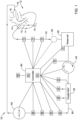
- FIG. 1 schematically illustrates selected aspects of a heart-lung machine (HLM) system 10.
- the HLM system 10 may be configured to bypass a patient's heart 12 during a cardiac procedure.
- the HLM system 10 may comprise a blood reservoir 20, an oxygenator 30, a pump 40, a clamp 50, and a controller 60. Other configurations are also contemplated.
- the HLM system 10 may comprise a plurality of venous sensors disposed along, coupled to, and/or in communication with the venous pathway 70.
- the plurality of venous sensors may be in fluid communication with the venous pathway 70 and/or fluid (e.g., blood, priming fluid, etc.) disposed and/or flowing therein.
- the plurality of venous sensors may be in communication (e.g., electronic communication, wired communication, wireless communication, etc.) with the controller 60.
- the plurality of venous sensors may include, but are not limited to, a venous blood gas sensor 72, a venous flow sensor 74, and/or a venous pressure sensor 76.
- the HLM system and/or the plurality of venous sensors may comprise one or more sensors for monitoring flow rates, pressures, temperatures, bubbles, oxygen saturation, carbon dioxide content, blood gases, or other fluid (e.g., blood, priming fluid, etc.) parameters.
- a single sensor may be configured to sense multiple fluid (e.g., blood, priming fluid, etc.) parameters including flow rate, pressures, temperatures, bubbles, oxygen saturation, carbon dioxide content, blood gases, etc.
- Other configurations are also contemplated. It is noted that the exact order and/or placement of the plurality of venous sensors disposed along, coupled to, and/or in communication with the venous pathway 70 may vary from that shown in the figures, unless expressly stated otherwise.
- the HLM system 10 may comprise an arterial pathway 80 fluidly couplable to the patient and/or the patient's vasculature (e.g., the heart, one or more arteries, etc.) for transporting oxygenated fluid (e.g., blood, priming fluid, etc.) within the HLM system 10 and/or from the HLM system 10 and/or the oxygenator 30 toward and/or to the patient's vasculature.
- oxygenated fluid e.g., blood, priming fluid, etc.
- the arterial pathway 80 may comprise tubing and/or a plurality of tubing portions extending between various components and/or elements of the arterial pathway 80 and/or extending between various components and/or elements disposed along the arterial pathway 80.
- the arterial pathway 80 may be configured to transport oxygenated fluid (e.g., blood, priming fluid, etc.) from the HLM system 10 and/or the oxygenator 30 to at least one arterial portion of the patient's vasculature.
- oxygenated fluid e.g., blood, priming fluid, etc.
- Other configurations are also contemplated.
- the second pump 22 may be in fluid communication with the venous pathway 70 and/or fluid (e.g., blood, priming fluid, etc.) disposed and/or flowing therein. In some embodiments, the second pump 22 may be disposed completely external to the venous pathway 70 and/or may be devoid of fluid communication with the fluid (e.g., blood, priming fluid, etc.) flowing within the venous pathway 70.
- fluid e.g., blood, priming fluid, etc.
- the second pump 22 may be in communication (e.g., electronic communication, wired communication, wireless communication, etc.) with the controller 60.
- the second pump 22 may be configured to generate fluid flow and/or pressure along and/or within the venous pathway 70, thereby enhancing the flow of fluid (e.g., blood, priming fluid, etc.) within the venous pathway 70 and/or to the blood reservoir 20.
- the second pump 22 may be a roller pump.
- the second pump 22 may be a centrifugal pump. Other configurations and/or pump types are also contemplated.
- the HLM system 10 and/or the blood reservoir 20 may comprise a blood level sensor 24 coupled to and/or in communication with the blood reservoir 20.
- the blood level sensor 24 may be integrated with the blood reservoir 20.
- the blood level sensor 24 may be configured to detect and/or monitor a level of fluid (e.g., blood, priming fluid, etc.) within the blood reservoir 20.
- the blood level sensor 24 may be configured to detect and/or monitor whether the level of fluid (e.g., blood, priming fluid, etc.) within the blood reservoir 20 falls below a predetermined minimum level.
- the blood level sensor 24 may be configured to detect and/or monitor whether the level of fluid (e.g., blood, priming fluid, etc.) within the blood reservoir 20 exceeds a predetermined maximum level. In some embodiments, the blood level sensor 24 may be configured to detect and/or monitor the level of fluid (e.g., blood, priming fluid, etc.) within the blood reservoir 20 at any time and/or at all times. For example, the blood level sensor 24 may be configured to detect and/or measure the level of fluid (e.g., blood, priming fluid, etc.) within the blood reservoir 20 continuously and/or at any level. The blood level sensor 24 may be in communication (e.g., electronic communication, wired communication, wireless communication, etc.) with the controller 60. Other configurations are also contemplated.
- the HLM system 10 may comprise the pump 40.
- the pump 40 may be disposed along, coupled to, and/or in communication with the venous pathway 70 downstream of the blood reservoir 20 and/or upstream of the oxygenator 30.
- the pump 40 may be in fluid communication with the venous pathway 70 and/or fluid (e.g., blood, priming fluid, etc.) disposed and/or flowing therein.
- the pump 40 may be disposed completely external to the venous pathway 70 and/or may be devoid of fluid communication with the fluid (e.g., blood, priming fluid, etc.) flowing within the venous pathway 70.
- the pump 40 may be in communication (e.g., electronic communication, wired communication, wireless communication, etc.) with the controller 60.
- the controller 60 may be configured to generate fluid flow and/or pressure along and/or within the venous pathway 70 using the pump 40, thereby causing the flow of fluid (e.g., blood, priming fluid, etc.) within the venous pathway 70 and/or from the blood reservoir 20 to the oxygenator 30.
- the pump 40 may be a roller pump.
- the pump 40 may be a centrifugal pump. Other configurations and/or pump types are also contemplated.
- the function of the pump 40 is to generate blood flow within the HLM system (e.g., circulate blood from the patient to the oxygenator and back to the patient) and to also generate blood pressure and facilitate blood flow within the patient's vasculature.
- the controller 60 may be configured to generate fluid flow and/or pressure along and/or within the arterial pathway 80 and/or at least a portion of the venous pathway 70 using the pump 40, thereby causing the flow of fluid (e.g., blood, priming fluid, etc.) within the venous pathway 70 and/or the arterial pathway 80 downstream of and/or from the blood reservoir 20, through the oxygenator 30, and/or to the arterial portion of the patient's vasculature.
- fluid e.g., blood, priming fluid, etc.
- Other configurations are also contemplated.
- the controller 60 may be configured to utilize feedback and/or signals from the blood level sensor 24 to control and/or modulate the pump 40 and/or the second pump 22 (where present) to control and/or manipulate the level of fluid (e.g., blood, priming fluid, etc.) within the blood reservoir 20.
- the level of fluid e.g., blood, priming fluid, etc.
- the controller 60 may be configured to change parameters associated with the pump 40 and/or the second pump 22 to increase the flow of fluid (e.g., blood, priming fluid, etc.) into the blood reservoir 20 and/or to decrease the flow of fluid (e.g., blood, priming fluid, etc.) out of the blood reservoir 20 so as to increase the level of fluid (e.g., blood, priming fluid, etc.) within the blood reservoir 20.
- the controller 60 may be configured to change parameters associated with the pump 40 and/or the second pump 22 to increase the flow of fluid (e.g., blood, priming fluid, etc.) into the blood reservoir 20 and/or to decrease the flow of fluid (e.g., blood, priming fluid, etc.) out of the blood reservoir 20 so as to increase the level of fluid (e.g., blood, priming fluid, etc.) within the blood reservoir 20.
- the controller 60 may be configured to change parameters associated with the pump 40 and/or the second pump 22 to decrease the flow of fluid (e.g., blood, priming fluid, etc.) into the blood reservoir 20 and/or to increase the flow of fluid (e.g., blood, priming fluid, etc.) out of the blood reservoir 20 so as to decrease the level of fluid (e.g., blood, priming fluid, etc.) within the blood reservoir 20.
- the controller 60 may be configured to change parameters associated with the pump 40 and/or the second pump 22 to decrease the flow of fluid (e.g., blood, priming fluid, etc.) into the blood reservoir 20 and/or to increase the flow of fluid (e.g., blood, priming fluid, etc.) out of the blood reservoir 20 so as to decrease the level of fluid (e.g., blood, priming fluid, etc.) within the blood reservoir 20.
- Other configurations are also contemplated.
- the HLM system 10 and/or the pump 40 may comprise a pump inlet pressure sensor 42 coupled to and/or in communication with the pump 40 and/or the venous pathway 70 at and/or proximate a fluid inlet into the pump 40.
- the pump inlet pressure sensor 42 may be integrated with the pump 40.
- the pump inlet pressure sensor 42 may be configured to detect and/or measure a fluid pressure of the fluid (e.g., blood, priming fluid, etc.) flowing within the venous pathway 70 as it enters the pump 40.
- the pump inlet pressure sensor 42 may be in communication (e.g., electronic communication, wired communication, wireless communication, etc.) with the controller 60.
- the pump inlet pressure sensor 42 may be used by the controller 60 to modulate and/or control the pump 40 (e.g., pump speed, voltage and/or current supplied, etc.) to generate the correct and/or desired flow rate and/or pressure downstream of the pump 40.
- the controller 60 may vary a pump speed of the pump 40 based on the fluid pressure detected by the pump inlet pressure sensor 42. Other configurations are also contemplated.
- the HLM system 10 may comprise the oxygenator 30.
- the oxygenator 30 may include a housing having multiple chambers or pathways separated by a semi-permeable membrane, whereby the patient's blood may flow through one chamber or pathway, while a compressed air and oxygen gas mixture flows through another chamber or pathway.
- the semi-permeable membrane may include multiple microporous hollow fibers, each fiber having a lumen extending therethrough through which the compressed air and oxygen gas mixture flows.
- Gas exchange may occur via diffusion of the gases across the multiple microporous hollow fibers, whereby oxygen moves from the inside of the multiple microporous hollow fibers into the blood while carbon dioxide diffuses from the blood into the interior of the multiple microporous hollow fibers, where it is swept away by the compressed air and oxygen gas mixture flowing through the multiple microporous hollow fibers. This gas exchange allows for oxygenation of venous blood and removal of carbon dioxide.
- the oxygenator 30 may be disposed downstream of the blood reservoir 20. In some embodiments, the oxygenator 30 may be disposed downstream of the pump 40. In some embodiments, the blood reservoir 20 and the oxygenator 30 may be integrated and/or combined into a single unit. In some embodiments, the blood reservoir 20 and the oxygenator 30 may be separate units and/or structures that are fluidly coupled to together. Other configurations are also contemplated
- the HLM system 10 and/or the oxygenator 30 may comprise a heat exchanger (not explicitly shown) configured to heat and/or cool blood flowing therethrough prior to returning the blood to the arterial portion of the patient's vasculature.
- the heat exchanger may be integrated with the oxygenator 30.
- the oxygenator 30 and/or the heat exchanger may be coupled to and/or may be in fluid communication with the blood reservoir 20.
- the blood reservoir 20, the oxygenator 30, and/or the heat exchanger may be integrated and/or combined into a single unit.
- the oxygenator 30 and/or the heat exchanger may be integrated and/or combined into a single unit, while the blood reservoir 20 is a separate unit and/or structure that is fluidly coupled to the single unit comprising the oxygenator 30 and the heat exchanger.
- Other configurations are also contemplated.
- the HLM system 10 and/or the oxygenator 30 may comprise a pre-oxygenator pressure sensor 32 coupled to and/or in communication with the oxygenator 30 and/or the venous pathway 70 at and/or proximate a fluid inlet into the oxygenator 30.
- the pre-oxygenator pressure sensor 32 may be disposed upstream of the oxygenator 30 and downstream of the blood reservoir 20 and/or the pump 40. In some embodiments, the pre-oxygenator pressure sensor 32 may be integrated with the oxygenator 30.
- the pre-oxygenator pressure sensor 32 may be configured to detect and/or measure a fluid pressure of the fluid (e.g., blood, priming fluid, etc.) flowing within the venous pathway 70 as it enters the oxygenator 30.
- the pre-oxygenator pressure sensor 32 may be in communication (e.g., electronic communication, wired communication, wireless communication, etc.) with the controller 60.
- the pre-oxygenator pressure sensor 32 may be used by the controller 60 to modulate and/or control the pump 40 (e.g., pump speed, voltage and/or current supplied, etc.) to generate the correct and/or desired flow rate and/or pressure entering the oxygenator 30.
- the controller 60 may vary a pump speed of the pump 40 based on the fluid pressure detected by the pre-oxygenator pressure sensor 32. Other configurations are also contemplated.
- the compressed air and oxygen gas mixture may flow into the oxygenator 30 through an air inlet and out of the oxygenator 30 through an air outlet.
- the HLM system 10 and/or the oxygenator 30 may comprise a gas mixture flow sensor 34 and/or a capnograph sensor 36.
- the gas mixture flow sensor 34 may be coupled to and/or in communication with the oxygenator 30 at and/or proximate the air inlet into the oxygenator 30.
- the gas mixture flow sensor 34 may be integrated with the oxygenator 30.
- the gas mixture flow sensor 34 may be configured to detect and/or measure a flow rate of the compressed air and oxygen gas mixture flowing into the oxygenator 30.
- the gas mixture flow sensor 34 may be in communication (e.g., electronic communication, wired communication, wireless communication, etc.) with the controller 60. In some embodiments, the gas mixture flow sensor 34 may be used by the controller 60 to modulate and/or control the flow and/or mixture of the compressed air and oxygen gas mixture. Other configurations are also contemplated.
- the capnograph sensor 36 may be coupled to and/or in communication with the oxygenator 30 at and/or proximate the air outlet from the oxygenator 30. In some embodiments, the capnograph sensor 36 may be integrated with the oxygenator 30. In some embodiments, the capnograph sensor 36 may be configured to detect and/or measure an exhaled carbon dioxide (ExCO2) content in the compressed air and oxygen gas mixture leaving the oxygenator 30.
- ExCO2 exhaled carbon dioxide
- the exhaled carbon dioxide content may be indicative of and/or may approximately correspond to the carbon dioxide content of the exhaled air of a human being and may be related to and/or indicative of proper function of the oxygenator 30.
- the capnograph sensor 36 may be in communication (e.g., electronic communication, wired communication, wireless communication, etc.) with the controller 60. Other configurations are also contemplated.
- the plurality of arterial sensors may include, but are not limited to, an arterial blood gas sensor 82, an arterial flow sensor 84, an arterial pressure sensor 86, and/or an arterial bubble sensor 88.
- the HLM system 10 and/or the plurality of arterial sensors may comprise one or more sensors for monitoring flow rates, pressures, temperatures, bubbles, oxygen saturation, carbon dioxide content, blood gases, or other fluid (e.g., blood, priming fluid, etc.) parameters.
- a single sensor may be configured to sense multiple fluid (e.g., blood, priming fluid, etc.) parameters including flow rate, pressures, temperatures, bubbles, oxygen saturation, carbon dioxide content, blood gases, etc. Other configurations are also contemplated. It is noted that the exact order and/or placement of the plurality of arterial sensors disposed along, coupled to, and/or in communication with the arterial pathway 80 may vary from that shown in the figures, unless expressly stated otherwise.
- the HLM system 10 may comprise the clamp 50.
- the clamp 50 may be disposed along, coupled to, and/or in communication with the arterial pathway 80 (e.g., the tubing and/or the plurality of tubing portions thereof) downstream of the oxygenator 30. It is noted that the exact placement of the clamp 50 disposed along, coupled to, and/or in communication with the arterial pathway 80 may vary from that shown in the figures, unless expressly stated otherwise.
- the clamp 50 may be in fluid communication with the arterial pathway 80 and/or fluid (e.g., blood, priming fluid, etc.) disposed and/or flowing therein.
- the clamp 50 may be disposed completely external to the arterial pathway 80 (e.g., the tubing and/or the plurality of tubing portions thereof) and/or may be devoid of fluid communication with the fluid (e.g., blood, priming fluid, etc.) flowing within the arterial pathway 80 (e.g., the tubing and/or the plurality of tubing portions thereof) to avoid contamination of the fluid (e.g., blood, priming fluid, etc.).
- the fluid e.g., blood, priming fluid, etc.
- the controller 60 may be configured to actuate the clamp 50 to change the cross-sectional area of the lumen of the arterial pathway 80 (e.g., the tubing and/or the plurality of tubing portions thereof) to increase and/or reduce the cross-sectional area of the lumen of the arterial pathway 80 and thereby change and/or affect fluid flow within the arterial pathway 80 (and by extension, the venous pathway 70 and the HLM system 10 as a whole).
- the clamp 50 may be configured to and/or may be capable of completely closing off the lumen of the arterial pathway 80, thereby stopping fluid flow within the arterial pathway 80 and/or the HLM system 10.
- the clamp 50 may be a manually operated and/or actuated clamp and control of the clamp 50 may be performed manually by a user or clinician. Other configurations are also contemplated.
- the clamp 50 may include one or more components (e.g., a ball valve, an iris, etc.) configured to adjust a cross-sectional area of a lumen within and/or passing through the clamp 50.
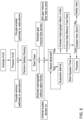
- the method of bypassing the patient's heart 12 with the heart-lung machine (HLM) system 10 may comprise suppressing alarms associated with the plurality of venous sensors until fluid (e.g., blood, priming fluid, etc.), or a particular type of fluid, such as blood, is detected within the venous pathway 70 by the venous blood gas sensor 72.
- the method of bypassing the patient's heart 12 with the heart-lung machine (HLM) system 10 may comprise suppressing alarms associated with the plurality of arterial sensors until fluid (e.g., blood, priming fluid, etc.), or a particular type of fluid, such as blood, is detected within the venous pathway 70 by the venous blood gas sensor 72.
- the method of bypassing the patient's heart 12 with the heart-lung machine (HLM) system 10 may comprise suppressing alarms associated with the gas mixture flow sensor 34 until fluid (e.g., blood, priming fluid, etc.), or a particular type of fluid, such as blood, is detected within the venous pathway 70 by the venous blood gas sensor 72.
- fluid e.g., blood, priming fluid, etc.
- a particular type of fluid such as blood
- the method of bypassing the patient's heart 12 with the heart-lung machine (HLM) system 10 may comprise suppressing alarms associated with the capnograph sensor 36 until fluid (e.g., blood, priming fluid, etc.), or a particular type of fluid, such as blood, is detected within the venous pathway 70 by the venous blood gas sensor 72.
- fluid e.g., blood, priming fluid, etc.
- a particular type of fluid such as blood
- the method of bypassing the patient's heart 12 with the heart-lung machine (HLM) system 10 may comprise automatically activating alarm limits associated with the capnograph sensor 36 configured to detect the exhaled carbon dioxide (ExCO2) content leaving the oxygenator 30 of the HLM system 10 upon detection of fluid (e.g., blood, priming fluid, etc.), or a particular type of fluid, such as blood, within the venous pathway 70 by the venous blood gas sensor 72.
- fluid e.g., blood, priming fluid, etc.
- the method of bypassing the patient's heart 12 with the heart-lung machine (HLM) system 10 may comprise, after starting the case within the controller 60 and while suppressing alarms associated with the plurality of venous sensors, the plurality of arterial sensors, the capnograph sensor 36, the gas mixture flow sensor 34, , and/or other sensors, continuously checking and re-checking for the presence and/or detection of fluid (e.g., blood, priming fluid, etc.), or a particular type of fluid, such as blood, within the venous pathway 70 by the venous blood gas sensor 72.
- fluid e.g., blood, priming fluid, etc.
- the controller 60 may activate a blood detection notification.
- the method of bypassing the patient's heart 12 with the heart-lung machine (HLM) system 10 may comprise, upon initial detection of fluid (e.g., blood, priming fluid, etc.), or a particular type of fluid, such as blood, is detected within the venous pathway 70 by the venous blood gas sensor 72, activating the bypass timer 66 to document the amount of time that blood flow bypasses the patient's heart 12 while the HLM system 10 is active.
- bypass timer 66 may be activated manually by the user.
- fluid e.g., blood, priming fluid, etc.
- the bypass timer 66 may be activated manually by the user.
- Other configurations are also contemplated.
Landscapes
- Health & Medical Sciences (AREA)
- Heart & Thoracic Surgery (AREA)
- Vascular Medicine (AREA)
- Cardiology (AREA)
- Biomedical Technology (AREA)
- Anesthesiology (AREA)
- Engineering & Computer Science (AREA)
- Hematology (AREA)
- Life Sciences & Earth Sciences (AREA)
- Animal Behavior & Ethology (AREA)
- General Health & Medical Sciences (AREA)
- Public Health (AREA)
- Veterinary Medicine (AREA)
- Pulmonology (AREA)
- External Artificial Organs (AREA)
Applications Claiming Priority (1)
| Application Number | Priority Date | Filing Date | Title |
|---|---|---|---|
| US18/541,535 US20250195738A1 (en) | 2023-12-15 | 2023-12-15 | Heart-lung bypass machine system and methods |
Publications (2)
| Publication Number | Publication Date |
|---|---|
| EP4582115A2 true EP4582115A2 (de) | 2025-07-09 |
| EP4582115A3 EP4582115A3 (de) | 2025-09-03 |
Family
ID=93566295
Family Applications (1)
| Application Number | Title | Priority Date | Filing Date |
|---|---|---|---|
| EP24213602.6A Pending EP4582115A3 (de) | 2023-12-15 | 2024-11-18 | Herz-lungen-bypassmaschinensystem |
Country Status (2)
| Country | Link |
|---|---|
| US (1) | US20250195738A1 (de) |
| EP (1) | EP4582115A3 (de) |
Family Cites Families (7)
| Publication number | Priority date | Publication date | Assignee | Title |
|---|---|---|---|---|
| US20080027368A1 (en) * | 2000-09-27 | 2008-01-31 | Sorin Group Usa, Inc. | Disposable cartridge for a blood perfusion system |
| US7022099B2 (en) * | 2003-03-17 | 2006-04-04 | Cardiovention, Inc. | Extracorporeal blood handling system with automatic flow control and methods of use |
| EP3295340B1 (de) * | 2015-05-13 | 2020-12-30 | Maquet Cardiopulmonary GmbH | System zur berechnung, simulation und überwachung klinischer parameter |
| CN108697840B (zh) * | 2015-10-07 | 2022-05-13 | 迈奎特心肺有限公司 | 用户界面 |
| US12246122B2 (en) * | 2021-05-07 | 2025-03-11 | Terumo Cardiovascular Systems Corporation | Heart-lung machine with semi-autonomous initiation mode |
| US20220370702A1 (en) * | 2021-05-20 | 2022-11-24 | Terumo Cardiovascular Systems Corporation | Perfusion Monitoring and Control System |
| CN119325396A (zh) * | 2022-06-09 | 2025-01-17 | 马奎特紧急护理公司 | 用于气体交换分析的多重采样侧流气体分析仪 |
-
2023
- 2023-12-15 US US18/541,535 patent/US20250195738A1/en active Pending
-
2024
- 2024-11-18 EP EP24213602.6A patent/EP4582115A3/de active Pending
Also Published As
| Publication number | Publication date |
|---|---|
| EP4582115A3 (de) | 2025-09-03 |
| US20250195738A1 (en) | 2025-06-19 |
Similar Documents
| Publication | Publication Date | Title |
|---|---|---|
| CN102781496B (zh) | 用于为体外血液治疗监测血管通路的装置和方法 | |
| WO2011021978A1 (en) | Coordinated control of ventilator and lung assist device | |
| CN105813665A (zh) | 用于调节和给出血液泵的泵速率的装置和方法 | |
| JP7328228B2 (ja) | 心臓血管の外部サポート循環装置において、血液性状値を連続的に監視するためのデバイス | |
| CN109922845B (zh) | 用于氧合器性能评估的系统和方法 | |
| US20210260266A1 (en) | System for control of a blood gas exchanger | |
| US20250170320A1 (en) | Heart-lung machine with semi-autonomous initiation mode | |
| EP4378495A2 (de) | Extrakorporales lebensunterstützungssystem | |
| EP4582115A2 (de) | Herz-lungen-bypassmaschinensystem | |
| JP7553950B2 (ja) | 補助循環制御装置、補助循環システム | |
| CN116439871B (zh) | 一种用于动物的ecmo实验装置及其方法 | |
| WO2025022103A1 (en) | Monitoring a parameter during cardiac perfusion | |
| EP4736906A1 (de) | Extrakorporales lebensunterstützungssystem mit entlüftungssteuerung | |
| EP3954406B1 (de) | Mikroplegieabgabesystem | |
| EP4545115A1 (de) | Extrakorporales lebensunterstützungssystem mit verstopfungserkennung | |
| EP4732887A1 (de) | Rollenpumpe zur verwendung mit einem perfusionssystem und zugehörige verfahren | |
| US20220184293A1 (en) | Gas delivery system | |
| EP4732888A1 (de) | Rollenpumpe zur verwendung mit einem perfusionssystem und zugehörige verfahren | |
| Dhinakaran et al. | A study and development of auto tuning control in a perfusion system for extracorporeal membrane oxygenator | |
| Baker et al. | Management of cardiopulmonary bypass | |
| Böckler et al. | Heart—Lung Machines | |
| WO2005032621A1 (en) | Hameoperfusion apparatus for use during cardiac and/or vascular operative procedures |
Legal Events
| Date | Code | Title | Description |
|---|---|---|---|
| PUAI | Public reference made under article 153(3) epc to a published international application that has entered the european phase |
Free format text: ORIGINAL CODE: 0009012 |
|
| STAA | Information on the status of an ep patent application or granted ep patent |
Free format text: STATUS: THE APPLICATION HAS BEEN PUBLISHED |
|
| AK | Designated contracting states |
Kind code of ref document: A2 Designated state(s): AL AT BE BG CH CY CZ DE DK EE ES FI FR GB GR HR HU IE IS IT LI LT LU LV MC ME MK MT NL NO PL PT RO RS SE SI SK SM TR |
|
| PUAL | Search report despatched |
Free format text: ORIGINAL CODE: 0009013 |
|
| AK | Designated contracting states |
Kind code of ref document: A3 Designated state(s): AL AT BE BG CH CY CZ DE DK EE ES FI FR GB GR HR HU IE IS IT LI LT LU LV MC ME MK MT NL NO PL PT RO RS SE SI SK SM TR |
|
| RIC1 | Information provided on ipc code assigned before grant |
Ipc: A61M 1/36 20060101AFI20250730BHEP |
|
| STAA | Information on the status of an ep patent application or granted ep patent |
Free format text: STATUS: REQUEST FOR EXAMINATION WAS MADE |
|
| 17P | Request for examination filed |
Effective date: 20251008 |