EP4580327A1 - Elektronisches system und verfahren zur montage davon - Google Patents
Elektronisches system und verfahren zur montage davon Download PDFInfo
- Publication number
- EP4580327A1 EP4580327A1 EP24221921.0A EP24221921A EP4580327A1 EP 4580327 A1 EP4580327 A1 EP 4580327A1 EP 24221921 A EP24221921 A EP 24221921A EP 4580327 A1 EP4580327 A1 EP 4580327A1
- Authority
- EP
- European Patent Office
- Prior art keywords
- adapter
- positioning member
- electronic module
- positioning
- heat sink
- Prior art date
- Legal status (The legal status is an assumption and is not a legal conclusion. Google has not performed a legal analysis and makes no representation as to the accuracy of the status listed.)
- Pending
Links
Images


Classifications
-
- H—ELECTRICITY
- H05—ELECTRIC TECHNIQUES NOT OTHERWISE PROVIDED FOR
- H05K—PRINTED CIRCUITS; CASINGS OR CONSTRUCTIONAL DETAILS OF ELECTRIC APPARATUS; MANUFACTURE OF ASSEMBLAGES OF ELECTRICAL COMPONENTS
- H05K7/00—Constructional details common to different types of electric apparatus
- H05K7/20—Modifications to facilitate cooling, ventilating, or heating
- H05K7/2089—Modifications to facilitate cooling, ventilating, or heating for power electronics, e.g. for inverters for controlling motor
- H05K7/209—Heat transfer by conduction from internal heat source to heat radiating structure
Definitions
- the present invention relates to the field of power electronics and in particular the field of electric motor power supply equipment.
- the present invention relates more particularly to an electronic system as well as a method of assembling such a system.
- the invention can find its application, for example, in electronic systems for traction inverters, for on-board chargers, for electric cooling pumps, for example, for batteries, for heat pumps, for laser sensors, for example for autonomous driving, etc.
- Electronic systems may include so-called "wideband” electronic modules.
- These electronic modules may include semiconductor chips, for example, made of silicon carbide or gallium nitride.
- the connection tracks (or " leadframe " in English terminology) can no longer be used to control or drive the chips, due to their inductive effect. It is therefore advisable to use electrical control or pilot pins that are as straight and short as possible. These electrical pins emerge vertically from the electronic module and are generally assembled using sleeves (or " sleeves " in English terminology) soldered onto the electronic module.
- One aim of the invention is in particular to correct all or part of the drawbacks of the prior art by proposing a solution making it possible to reduce the placement dispersions linked in particular to the assembly process of the electronic module(s) and the electronic system.
- the first and fifth positioning members are merged.
- the at least one third positioning member is located less than ten millimeters from an electrical control pin of the adapter.
- the adapter comprises at least two third positioning members, each of the at least two third positioning members being located at one end of the adapter.
- one of the at least two third positioning members is cylindrical in shape and one of the at least two third positioning members is oblong in shape.
- the adapter comprises at least two electrical control pins, said electrical control pins being aligned and overmolded together in the adapter.
- the electrical control pins and the at least one second positioning member of the adapter are overmolded together in the adapter.
- the electronic module comprises a power module or an excitation module.
- the adapter is attached to the electronic module via the at least one electrical control pin.
- one of the first and second positioning members is a male-shaped member and the other is a female-shaped member.
- the first and second positioning members are female in shape.
- the first and second positioning members are coaxial.
- one of the third and fourth positioning members is a male-shaped member and the other is a female-shaped member.
- the third and fourth positioning members are coaxial.
- a second indexing tool causes the third and fifth positioning members or the third, fourth and fifth positioning members to cooperate.
- the fixing step is carried out via at least one electrical control pin.
- the step of fixing the electronic module to the heat sink is carried out by gluing, welding, brazing or sintering.
- the electronic system 1 comprises a heat sink 11, at least one electronic module 12 and at least one adapter 13.
- the electronic system comprises two electronic modules 12 each comprising an adapter 13, the whole being mounted on the same heat sink 11.
- a first electronic module 12 may comprise a power module, for example, configured to power the stator of a rotating electrical machine.
- the second electronic module 12 may comprise an excitation module, for example, configured to power the rotor of a rotating electrical machine.
- the electronic module 12 may comprise a power module or an excitation module.
- the electronic module 12 is configured for use with at least one electronic device, not shown.
- the electronic module 12 is fixed to the heat sink 11, for example, by gluing, soldering, welding or sintering.
- each electrical module 12 is referenced relative to said heat sink 11.
- the heat sink 11 comprises at least one first positioning member 111 defining at least one reference position on the heat sink 11. This reference position makes it possible to precisely determine the location of the electronic module 12 relative to the heat sink 11.
- the electronic module 12 comprises at least one second positioning member 121 configured to cooperate with the first positioning member 111.
- the first and second positioning members 111, 121 are members of complementary shape cooperating directly with each other.
- the first positioning member 111 is, for example, a male-shaped member and the second positioning member 121 is a female-shaped member. This embodiment is, for example, illustrated in the Figure 3 described below.
- the first positioning member 111 may be a pin or a protrusion of the heat sink 11.
- the second positioning member 121 may be an orifice or a through or blind hole in the electronic module 12.
- the second positioning member 121 of female shape, is arranged to allow the passage of the first positioning member 111, of male shape and to provide it with a housing.
- the first positioning member 111 is a female-shaped member and the second positioning member 121 is a male-shaped member.
- FIG. 2 illustrates another embodiment in which the first positioning member 111 and the second positioning member 121 are female-shaped members.
- a first indexing tool can be used to make the first and second positioning members 111, 121 cooperate.
- the first indexing tool is arranged to be inserted into the first and second positioning members 111, 121 and to align the electronic module 12 relative to the heat sink 11. The first tool thus makes it possible to precisely position the electronic module 12 relative to the heat sink 11.
- the first indexing tool could be a tool having a plurality of indexing fingers, for example three, for example four, arranged to be inserted into the first positioning member 111 on the one hand and the two second members of positioning 121 on the other hand in order to reference the electronic module 12 relative to the heat sink 11.
- the first and second positioning members 111, 121 are not aligned vertically, that is to say not aligned with respect to the normal to the plane defined by the surface of the heat sink 11. According to another embodiment, the first and second positioning members 111, 121 are aligned vertically. In this embodiment, the first indexing tool is arranged to make the first and second positioning members 111, 121 coincide two by two.
- the first and second positioning members 111, 121 are coaxial.
- At least one electronic module 12 comprises at least two second positioning members 121, said at least two second positioning members 121 being located close; in particular of the order of a few millimeters, to two opposite edges of the electronic module 12.
- a male-shaped part for example a pin or a screw, is inserted into the first and second female-shaped positioning members 111, 121, in order to align the electronic module 12 with the heat sink 11.
- the adapter 13 is a part made of electrically non-conductive material such as resin or a plastic material.
- the adapter 13 is attached to the electronic module 12.
- the adapter can be attached to the electronic module using glue, for example, epoxy glue.
- the adapter 13 may comprise at least one reinforcing wall 135.
- the reinforcing wall 135 makes it possible to reinforce the rigidity of the adapter 13, in particular when the latter is of small thickness.
- the reinforcing wall also makes it possible to resist certain mechanical stresses, such as when gluing the adapter to the electronic module, where pressure is exerted on the adapter 13.
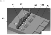
- the adapter 13 is configured to establish an electrical connection between the electronic module 12 and an electronic device via at least one electrical control pin 133.
- an adapter 13, within an electronic system 1 makes it possible to group together a large number of electrical control pins 133 of the same electronic module 12 on the same mechanical part.
- all of the electrical control pins 133 of the same electronic module 12 are grouped on the same adapter 13.
- the electrical control pins 133 are press-fit pins.
- the electronic module 12 comprises at least one connection zone 123 configured to allow the connection of one end of an electrical control pin 133.
- connection area 123 is made of an electrically conductive material and is configured so that the connection of the electrical control pin 133 can be made with a positioning margin chosen to compensate for the different placement dispersions.
- the connection area 123 has, for example, a surface area six times larger than the cross-section of the electrical control pin 133.
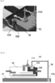
- the adapter 13 comprises two third positioning members 131 of female shape.
- One of the positioning members 131 is of cylindrical shape and another is of oblong shape.
- the cylindrical-shaped positioning member is called the “centering orifice” and the oblong-shaped one is called the “placement orifice”.
- the combination of the round and oblong shaped positioning holes allows isostatic positioning of the adapter 13 relative to the power module 12.
- THE figures 8 And 9 represent, respectively in a caval view and in a sectional view, the association of the third and fourth positioning members 131, 122 in another embodiment.
- the third and fourth positioning members 131, 122 are both female in shape, respectively a through hole and a blind hole.
- a second indexing tool can be used in order to make each pair of third and fourth positioning members 131, 122, respectively of the adapter and the electronic module, cooperate.
- This second tool can comprise at least one indexing finger configured to be inserted into the third and fourth positioning members 131, 122.
- the cooperation of the third and fifth positioning members 131, 112 is achieved by means of a second referencing tool 70.
- a first indexing tool causes the first and second positioning members 111, 121 to cooperate. This first tool is then held during the step of fixing the electronic module 12 to the heat sink 11 and is then removed.
- the step of fixing the electronic module 12 to the heat sink 11 is carried out, for example, by gluing, welding, brazing or by sintering the two mechanical parts 11, 12.
- a second indexing tool 70 is used in order to make the third and fifth positioning members 131, 112 cooperate.
- a second indexing tool 70 is used in order to make the third, fourth and fifth positioning members 131, 122, 112 cooperate.
- the assembly method further comprises a step of fixing the adapter 13 to the electronic module 12.
- the assembly method comprises, prior to the step of positioning the adapter 13 in contact with the electronic module 12, the depositing of a strip of glue 125 on the electronic module 12, as illustrated in the Figure 2
- the fixing step may consist of pressing the adapter 13 into contact with the electronic module 12 and then polymerizing the glue.
- one end of the electrical control pins 132 is fixed to the associated connection zones 123 but the adapter 13 is not glued to the electronic module 12.
- the adapter 13 is therefore fixed to the electronic module 12 by means of one end of the at least one electrical control pin 132.
- the second tool is held during the step of fixing the adapter 13 to the electronic module 12 and is then removed.
Landscapes
- Engineering & Computer Science (AREA)
- Microelectronics & Electronic Packaging (AREA)
- Physics & Mathematics (AREA)
- Thermal Sciences (AREA)
- Cooling Or The Like Of Electrical Apparatus (AREA)
- Cooling Or The Like Of Semiconductors Or Solid State Devices (AREA)
Applications Claiming Priority (1)
| Application Number | Priority Date | Filing Date | Title |
|---|---|---|---|
| FR2314960A FR3157782A1 (fr) | 2023-12-21 | 2023-12-21 | Système électronique et procédé d’assemblage associé |
Publications (1)
| Publication Number | Publication Date |
|---|---|
| EP4580327A1 true EP4580327A1 (de) | 2025-07-02 |
Family
ID=89661728
Family Applications (1)
| Application Number | Title | Priority Date | Filing Date |
|---|---|---|---|
| EP24221921.0A Pending EP4580327A1 (de) | 2023-12-21 | 2024-12-19 | Elektronisches system und verfahren zur montage davon |
Country Status (2)
| Country | Link |
|---|---|
| EP (1) | EP4580327A1 (de) |
| FR (1) | FR3157782A1 (de) |
Citations (4)
| Publication number | Priority date | Publication date | Assignee | Title |
|---|---|---|---|---|
| JP4936149B2 (ja) * | 2007-01-18 | 2012-05-23 | 株式会社安川電機 | モータ制御装置 |
| US20140204536A1 (en) * | 2013-01-24 | 2014-07-24 | Infineon Technologies Ag | Semiconductor Module Arrangement and Method for Producing a Semiconductor Module Arrangement |
| FR3014257A1 (fr) * | 2013-12-03 | 2015-06-05 | Valeo Equip Electr Moteur | Module electronique de puissance, procede de fabrication d'un tel module et machine electrique tournante polyphasee de vehicule automobile le comprenant |
| CN114172387A (zh) * | 2020-09-11 | 2022-03-11 | 采埃孚股份公司 | 制造逆变器的方法以及定位辅助装置和逆变器 |
-
2023
- 2023-12-21 FR FR2314960A patent/FR3157782A1/fr active Pending
-
2024
- 2024-12-19 EP EP24221921.0A patent/EP4580327A1/de active Pending
Patent Citations (4)
| Publication number | Priority date | Publication date | Assignee | Title |
|---|---|---|---|---|
| JP4936149B2 (ja) * | 2007-01-18 | 2012-05-23 | 株式会社安川電機 | モータ制御装置 |
| US20140204536A1 (en) * | 2013-01-24 | 2014-07-24 | Infineon Technologies Ag | Semiconductor Module Arrangement and Method for Producing a Semiconductor Module Arrangement |
| FR3014257A1 (fr) * | 2013-12-03 | 2015-06-05 | Valeo Equip Electr Moteur | Module electronique de puissance, procede de fabrication d'un tel module et machine electrique tournante polyphasee de vehicule automobile le comprenant |
| CN114172387A (zh) * | 2020-09-11 | 2022-03-11 | 采埃孚股份公司 | 制造逆变器的方法以及定位辅助装置和逆变器 |
Also Published As
| Publication number | Publication date |
|---|---|
| FR3157782A1 (fr) | 2025-06-27 |
Similar Documents
| Publication | Publication Date | Title |
|---|---|---|
| EP1886401B1 (de) | Elektronikmodul für eine elektrische drehmaschine | |
| EP1886397B1 (de) | Kühler für elektronische komponente einer elektrischen rotationsmaschine | |
| EP1886396B1 (de) | Rotierende elektrische Maschine mit ein Leistungsverbindungsstück | |
| WO2006129030A1 (fr) | Piece d'interconnexion de signal pour machine electrique tournante | |
| EP1886400B1 (de) | Anordnung elektronischer bauteile für eine elektrische rotationsmaschine | |
| EP2896067B1 (de) | Kappe für eine chipvorrichtung mit einer nut, vorrichtung mit besagter kappe, baugruppe aus dieser kappe und einem drahtelement sowie herstellungsverfahren dafür | |
| EP3939396B1 (de) | Elektronisches system und elektrische baugruppe | |
| EP3176919B1 (de) | Elektrischer steckverbinder zur elektrischen verbindung mit einer stromquelle | |
| EP4580327A1 (de) | Elektronisches system und verfahren zur montage davon | |
| WO2012085397A1 (fr) | Dispositif de connexion d'une carte electronique a une pluralite de composants | |
| EP1114456B1 (de) | Gemeinsames verfahren zum herstellen einer mehrzahl von bauelementen welche ursprünglich in dasselbe substrat geformt sind | |
| WO2020260141A1 (fr) | Capteur et procédé de fabrication | |
| EP3932152A1 (de) | Elektronische leiterplatte mit bauelementen in hohlräumen und geteilten lötpads | |
| WO2008000931A1 (fr) | Carte electronique pourvue d'un connecteur en deux parties et procede de fabrication d'une telle carte | |
| WO2010072914A1 (fr) | Composant électronique notamment capteur à effet hall | |
| EP4434300B1 (de) | Wechselrichter mit einer vorrichtung zur gegenseitigen ausrichtung von drei komponenten | |
| EP4154350A1 (de) | Elektrochemische einheit und zugehöriges herstellungsverfahren und anlage | |
| EP3109899B1 (de) | Elektronisches 3d-modul, das einen bga-stapel umfasst | |
| WO2025228926A1 (fr) | Dispositif d'interconnexion, procede de fabrication et aeronef associes | |
| WO2020012101A1 (fr) | Procede de fabrication d'un module electronique de puissance pour une électronique embarquée sur aeronef | |
| EP4734742A1 (de) | Elektronisches modul, elektronisches system, form und herstellungsverfahren dafür | |
| EP4734739A1 (de) | Anordnung mit einem leistungsmodul, einem temperatursensor und einer leiterplatte | |
| WO2018115708A1 (fr) | Ceinture de protection, module électronique de puissance et compresseur de suralimentation électrique pilote par un tel module électronique de puissance | |
| EP2386131A1 (de) | Impedanzanpassungsanordnung, elektronische schaltung und verwandte herstellungsverfahren | |
| FR2822632A1 (fr) | Carte electronique et circuit correspondant |
Legal Events
| Date | Code | Title | Description |
|---|---|---|---|
| PUAI | Public reference made under article 153(3) epc to a published international application that has entered the european phase |
Free format text: ORIGINAL CODE: 0009012 |
|
| STAA | Information on the status of an ep patent application or granted ep patent |
Free format text: STATUS: REQUEST FOR EXAMINATION WAS MADE |
|
| 17P | Request for examination filed |
Effective date: 20241219 |
|
| AK | Designated contracting states |
Kind code of ref document: A1 Designated state(s): AL AT BE BG CH CY CZ DE DK EE ES FI FR GB GR HR HU IE IS IT LI LT LU LV MC ME MK MT NL NO PL PT RO RS SE SI SK SM TR |