EP4580261A1 - Verfahren und vorrichtung für diskontinuierlichen empfang - Google Patents
Verfahren und vorrichtung für diskontinuierlichen empfang Download PDFInfo
- Publication number
- EP4580261A1 EP4580261A1 EP23867206.7A EP23867206A EP4580261A1 EP 4580261 A1 EP4580261 A1 EP 4580261A1 EP 23867206 A EP23867206 A EP 23867206A EP 4580261 A1 EP4580261 A1 EP 4580261A1
- Authority
- EP
- European Patent Office
- Prior art keywords
- information
- dci
- cdrx
- indicating
- time
- Prior art date
- Legal status (The legal status is an assumption and is not a legal conclusion. Google has not performed a legal analysis and makes no representation as to the accuracy of the status listed.)
- Pending
Links
Images


Classifications
-
- H—ELECTRICITY
- H04—ELECTRIC COMMUNICATION TECHNIQUE
- H04W—WIRELESS COMMUNICATION NETWORKS
- H04W52/00—Power management, e.g. Transmission Power Control [TPC] or power classes
- H04W52/02—Power saving arrangements
- H04W52/0209—Power saving arrangements in terminal devices
- H04W52/0212—Power saving arrangements in terminal devices managed by the network, e.g. network or access point is leader and terminal is follower
-
- H—ELECTRICITY
- H04—ELECTRIC COMMUNICATION TECHNIQUE
- H04W—WIRELESS COMMUNICATION NETWORKS
- H04W52/00—Power management, e.g. Transmission Power Control [TPC] or power classes
- H04W52/02—Power saving arrangements
- H04W52/0209—Power saving arrangements in terminal devices
- H04W52/0212—Power saving arrangements in terminal devices managed by the network, e.g. network or access point is leader and terminal is follower
- H04W52/0216—Power saving arrangements in terminal devices managed by the network, e.g. network or access point is leader and terminal is follower using a pre-established activity schedule, e.g. traffic indication frame
-
- H—ELECTRICITY
- H04—ELECTRIC COMMUNICATION TECHNIQUE
- H04W—WIRELESS COMMUNICATION NETWORKS
- H04W52/00—Power management, e.g. Transmission Power Control [TPC] or power classes
- H04W52/02—Power saving arrangements
- H04W52/0209—Power saving arrangements in terminal devices
- H04W52/0225—Power saving arrangements in terminal devices using monitoring of external events, e.g. the presence of a signal
- H04W52/0229—Power saving arrangements in terminal devices using monitoring of external events, e.g. the presence of a signal where the received signal is a wanted signal
-
- H—ELECTRICITY
- H04—ELECTRIC COMMUNICATION TECHNIQUE
- H04W—WIRELESS COMMUNICATION NETWORKS
- H04W52/00—Power management, e.g. Transmission Power Control [TPC] or power classes
- H04W52/02—Power saving arrangements
- H04W52/0209—Power saving arrangements in terminal devices
- H04W52/0261—Power saving arrangements in terminal devices managing power supply demand, e.g. depending on battery level
- H04W52/0274—Power saving arrangements in terminal devices managing power supply demand, e.g. depending on battery level by switching on or off the equipment or parts thereof
- H04W52/028—Power saving arrangements in terminal devices managing power supply demand, e.g. depending on battery level by switching on or off the equipment or parts thereof switching on or off only a part of the equipment circuit blocks
-
- H—ELECTRICITY
- H04—ELECTRIC COMMUNICATION TECHNIQUE
- H04W—WIRELESS COMMUNICATION NETWORKS
- H04W76/00—Connection management
- H04W76/20—Manipulation of established connections
- H04W76/28—Discontinuous transmission [DTX]; Discontinuous reception [DRX]
-
- Y—GENERAL TAGGING OF NEW TECHNOLOGICAL DEVELOPMENTS; GENERAL TAGGING OF CROSS-SECTIONAL TECHNOLOGIES SPANNING OVER SEVERAL SECTIONS OF THE IPC; TECHNICAL SUBJECTS COVERED BY FORMER USPC CROSS-REFERENCE ART COLLECTIONS [XRACs] AND DIGESTS
- Y02—TECHNOLOGIES OR APPLICATIONS FOR MITIGATION OR ADAPTATION AGAINST CLIMATE CHANGE
- Y02D—CLIMATE CHANGE MITIGATION TECHNOLOGIES IN INFORMATION AND COMMUNICATION TECHNOLOGIES [ICT], I.E. INFORMATION AND COMMUNICATION TECHNOLOGIES AIMING AT THE REDUCTION OF THEIR OWN ENERGY USE
- Y02D30/00—Reducing energy consumption in communication networks
- Y02D30/70—Reducing energy consumption in communication networks in wireless communication networks
Definitions
- the disclosure relates to the field of communication, and in particular to a method and apparatus for discontinuous reception.
- Extended reality provides a new human-computer interaction method.
- an XR service featuring a large data volume and a high delay requirement, poses new challenges to development of a wireless network.
- Connected mode discontinuous reception CDRX
- CDRX Connected mode discontinuous reception
- a power saving amplitude is limited.
- the main reason is that jitter exists in an actual XR system. That is, when a base station receives a data packet (a data frame) of the XR service, jitter exists due to a frame coding delay and a change of network transmission time.
- the disclosure provides a method and apparatus for discontinuous reception, so as to guarantee an energy and power saving effect.
- a method for discontinuous reception is provided and is applied to user equipment.
- the method includes: receiving indication information transmitted by a network device, where the indication information is used for indicating whether data arrive ahead of time or indicating that data arrive with lag; and monitoring a physical downlink control channel according to the indication information.
- the physical downlink control channel is monitored according to the indication information, such that reception of the data arriving ahead of time or arriving with lag caused by jitter is guaranteed, and loss of such data is prevented.
- a time length of an on duration timer in connected mode discontinuous reception does not need to be prolonged for completely covering a jitter interval, so as to further save power.
- the data may be a data frame of an extended reality (XR) service, a data packet of another service, or other data that can be transmitted and received in a connected mode discontinuous reception (CDRX) mechanism, which are not limited.
- XR extended reality
- CDRX connected mode discontinuous reception
- the indication information includes first information, the first information is used for indicating whether the data arrive ahead of time, and arrival ahead of time is used for indicating that the data arrive before the first information is received; and the monitoring a physical downlink control channel (PDCCH) according to the indication information may include: monitoring, when the data arrive ahead of time, the PDCCH according to a configuration parameter of CDRX indicated by the first information.
- PDCCH physical downlink control channel
- the first information includes first downlink control information (DCI), and a first preset bit in the first DCI is used for indicating whether the data arrive ahead of time.
- DCI downlink control information
- the first DCI is UE-group common signaling DCI.
- At least one bit other than the first preset bit in the first DCI is used for indicating at least one parameter in the configuration parameters of the CDRX or indicating an identifier of a parameter set of the configuration parameters of the CDRX, and the parameter set includes at least one configuration parameter of the CDRX.
- the configuration parameters of the CDRX includes at least one of offset, an on duration timer, an inactivity timer, or a search space set group; and the monitoring, when the data arrive ahead of time, the PDCCH according to a configuration parameter of CDRX indicated by the first information may include at least one of the following operations: starting the on duration timer ahead of time according to the offset indicated by the first information, and monitoring the PDCCH in the on duration timer; or performing monitoring by using the dense search space set group according to an indication of the first information; or performing monitoring according to the on duration timer indicated by the first information; or performing monitoring according to the inactivity timer indicated by the first information.
- the method further includes: performing monitoring according to a first preset configuration parameter of the CDRX when the data do not arrive ahead of time, where the first preset configuration parameter is a preset configuration parameter corresponding to a situation that the data do not arrive ahead of time. That is, in this implementation, two configuration parameters of the first preset configuration parameter and a second preset configuration parameter are preconfigured for the CDRX. Two cases, that is, data do not arrive ahead of time and data arrive ahead of time, correspond to the first preset configuration parameter and the second preset configuration parameter respectively.
- the user equipment may select the first preset configuration parameter for monitoring when it is determined, according to the received first information, that the data do not arrive ahead of time.
- the indication information includes second information, and the second information is used for indicating that the data arrive with lag; and the monitoring a PDCCH according to the indication information may include: monitoring the PDCCH according to the second information.
- the second information includes second DCI; the second DCI does not schedule a corresponding physical downlink shared channel (PDSCH); and the monitoring the PDCCH according to the second information may include: monitoring the PDCCH by starting a first timer in response to the second DCI; or monitoring the PDCCH according to a configuration parameter of CDRX indicated by the second DCI.
- PDSCH physical downlink shared channel
- the case that the second DCI does not schedule the corresponding PDSCH is indicated by using a time domain resource assignment (TDRA) domain in the second DCI.
- TDRA time domain resource assignment
- At least one bit other than the TDRA domain in the second DCI is used for indicating at least one parameter in the configuration parameters of the CDRX or indicating an identifier of a parameter set of the configuration parameters of the CDRX, and the parameter set includes at least one configuration parameter of the CDRX.
- the second information includes third DCI; a PDSCH scheduled by the third DCI is a padding PDSCH; and the monitoring the PDCCH according to the second information may include: monitoring the PDCCH by starting a second timer in response to the third DCI.
- a method for discontinuous reception is provided and is applied to a network device.
- the method includes: transmitting indication information to user equipment (UE), where the indication information is used for indicating whether data arrive ahead of time or for indicating that data arrive with lag.
- UE user equipment
- the first information includes first downlink control information (first DCI).
- first DCI first downlink control information
- a first preset bit in the first DCI is used for indicating whether the data arrive ahead of time.
- the first DCI is UE-group common signaling DCI.
- At least one bit other than the first preset bit in the first DCI is used for indicating at least one parameter in the configuration parameters of the CDRX or indicating an identifier of a parameter set of the configuration parameters of the CDRX, and the parameter set includes at least one configuration parameter of the CDRX.
- the configuration parameters of the CDRX includes at least one of offset, an on duration timer, an inactivity timer, or a search space set group.
- the indication information includes second information, and the second information is used for indicating that the data arrive with lag.
- the second information includes second DCI; and the second DCI does not schedule a corresponding physical downlink shared channel (PDSCH), and the second DCI is used for indicating arrival with lag.
- PDSCH physical downlink shared channel
- the case that the second DCI does not schedule the corresponding PDSCH is indicated by using a time domain resource assignment (TDRA) domain in the second DCI.
- TDRA time domain resource assignment
- At least one bit other than the TDRA domain in the second DCI is used for indicating at least one parameter in the configuration parameters of the CDRX or indicating an identifier of a parameter set of the configuration parameters of the CDRX, and the parameter set includes at least one configuration parameter of the CDRX.
- the second information includes third DCI; and a PDSCH scheduled by the third DCI is a padding PDSCH.
- an apparatus for discontinuous reception includes a unit that is formed by software and/or hardware and that is configured to perform any method according to the first aspect or the second aspect.
- an electronic device includes a memory, a processor, and a computer program stored in the memory and capable of being run on the processor.
- the processor executes the computer program, the electronic device may implement any method according to the first aspect or the second aspect.
- the electronic device when the electronic device is configured to implement any method according to the first aspect, the electronic device may be user equipment.
- the electronic device when the electronic device is configured to implement any method according to the second aspect, the electronic device may be a network device.
- a chip includes a processor.
- the processor is configured to read and perform a computer program stored in a memory.
- an electronic device where the chip is located may implement any method according to the first aspect or the second aspect.
- the chip further includes a memory, and the memory is electrically connected to the processor.
- the chip may further include a communication interface.
- a computer-readable storage medium stores a computer program.
- the computer program may implement any method according to the first aspect or the second aspect when executed by an electronic device.
- a computer program product includes a computer program.
- the computer program may implement any method according to the first aspect or the second aspect when executed by an electronic device.
- the method for discontinuous reception provided in the disclosure may be applied to various wireless communication systems.
- FIG. 1 is a schematic diagram of an applicable network scenario according to an embodiment of the disclosure; as shown in FIG. 1 , the wireless communication system in such a scenario includes at least one network device 110 and at least one piece of user equipment (UE) 120.
- the wireless communication system may be a long term evolution (LTE) network, a fifth generation (5G) network, a future sixth generation (6G) network, or various subsequent evolved wireless communication systems that can bear an extended reality (XR) service.
- LTE long term evolution
- 5G fifth generation
- 6G future sixth generation
- XR extended reality
- the network device 110 may include an access network (AN) device and a radio access network (RAN) device.
- the access network device for example, a base station (for example, an access point), may refer to a device that is in communication with a wireless terminal device in an air interface through one or more cells.
- the base station for example, may be an evolved Node B (NodeB, eNB, or e-NodeB), may include a next generation node B (gNB), a next generation evolved nodeB (ng-e B), or an enhanced next generation node B (gNB): an enhanced next generation base station in the 5G system, or may include a centralized unit (CU), a distributed unit (DU), etc. in a cloud radio access network (Cloud RAN) system, which are not listed one by one.
- NodeB evolved Node B
- gNB next generation node B
- ng-e B next generation evolved nodeB
- gNB enhanced next generation node B
- 5G system or may include a centralized unit (
- the user equipment may alternatively be referred to as a terminal device, and may be a mobile phone, a smartwatch, a tablet computer, a notebook computer, an XR terminal, an in-vehicle terminal, etc.
- the XR terminal may further include a virtual reality (VR) terminal, an augmented reality (AR) terminal, and a mixed reality (MR) terminal.
- VR virtual reality
- AR augmented reality
- MR mixed reality
- FIG. 2 is a schematic diagram of periodic transmission of a data frame of an XR service according to an embodiment of the disclosure.
- the data frame of the XR service is periodically transmitted.
- a transmission period is 8.33 milliseconds. That is, the 8 transmission period in FIG. 2 may be 8.33 milliseconds.
- user equipment periodically receives and transmits the data frame
- a network device periodically receives and transmits the data frame at a same period.
- one piece of user equipment periodically transmits data frames
- a network device periodically receives these data frames at a same period and transmits these data to another piece of user equipment at the same period
- the another piece of user equipment also periodically receives these data frames in the same period.
- jitter exists when the network device receives a data frame.
- a time length of arrival ahead of time, arrival with lag, etc. may be referred to as jitter.
- jitter 1 indicates jitter of the time length of arrival ahead of time
- jitter 2 indicates jitter of the time length of arrival with lag.
- a value of the jitter is a random variable between -4 milliseconds to +4 milliseconds. That is, in FIG. 2 , a value range of jitter 2 is (0, +4], a value range of jitter 1 is [-4, 0), and the unit is millisecond.
- the on duration timer needs at least 8 milliseconds, which reduces a power saving effect, that is, the on duration timer occupies 8 milliseconds in a CDRX period.
- a too long or too short inactivity timer also has a similar problem described above, that is, a too long inactivity timer consumes electricity, and a too short inactivity timer misses a data frame.
- the network device informs the user equipment in advance of whether data arrive ahead of time, and/or at a moment after the on duration timer is started, if no data are received, the network device informs the user equipment that data arrive with lag.
- the user equipment may use, according to such an indication, a corresponding configuration parameter of the CDRX to monitor a physical downlink control channel (PDCCH).
- PDCCH physical downlink control channel
- the method of the embodiment of the disclosure may be applied to the XR service, and may alternatively be applied to other data transmission scenarios.
- FIG. 3 is a schematic flowchart of a method for discontinuous reception according to an embodiment of the disclosure.
- S301 A network device transmits indication information to UE.
- the indication information is used for indicating whether data arrive ahead of time or for indicating that data arrive with lag.
- the data may be a data frame of an extended reality (XR) service, a data packet of another service, or other data that can be transmitted and received in a connected mode discontinuous reception (CDRX) mechanism, which are not limited.
- XR extended reality
- CDRX connected mode discontinuous reception
- the arrival ahead of time may be understood as that the data arrive before the indication information of whether the data arrive ahead of time is transmitted.
- the arrival with lag may be understood as that the data do not arrive before the indication information of arrival with lag is transmitted.
- the network device may transmit the indication information to the UE, and after receiving the indication information, the UE may perform S302.
- the indication information includes first information.
- the first information is used for indicating whether the data arrive ahead of time.
- the arrival ahead of time is used for representing that the data arrive before the UE receives the first information.
- the arrival ahead of time is used for representing that the data arrive before the network device transmits the first information.
- the network device may periodically transmit the first information to the UE. If the network device has received the data when the first information is transmitted, the network device uses the first information to indicate that the data arrive ahead of time. If the network device does not receive data when the first information is transmitted, the network device uses the first information to indicate that the data do not arrive ahead of time. It should be understood that arrival not ahead of time may include two possibilities of normal arrival and arrival with lag. It should be further understood that the first information is transmitted regardless of whether the data are received. The first information is periodically transmitted, and carries, when transmitted, an indication whether the data are received at a transmission moment.
- the first information transmitted by the network device to the UE is not periodically transmitted, but the first information is not transmitted when the data do not arrive ahead of time. In this case, if no first information is decoded by the UE, it is considered by default that the data do not arrive ahead of time.
- the first information includes first downlink control information (DCI), and a first preset bit in the first DCI is used for indicating whether the data arrive ahead of time. That is, whether the data arrive ahead of time may be indicated by using the DCI.
- DCI downlink control information
- the first DCI may be UE-group common signaling DCI. That is, one piece of DCI includes indications for a plurality of pieces of UE.
- a field (a bit) corresponding to the UE may be found from the indications, and then indicated information is read from the field.
- target UE in the first DCI corresponds to N bits, and a bit of the N bits may be used as the first preset bit.
- a first bit in the N bits may be used as the first preset bit, and the first bit includes an indication of whether the data arrive ahead of time.
- the case that the first preset bit indicates that the data arrive ahead of time may be, for example, that when the first preset bit is 0, it indicates that the data do not arrive ahead of time, and when the first preset bit is 1, it indicates that the data arrive ahead of time.
- a structure of the first DCI may be user-defined, or may be implemented by modifying a structure of existing DCI.
- the first DCI may be a structure of DCI2_6, and bits of the DCI2_6 are redefined to satisfy a requirement of the first DCI.
- the configuration parameter of the CDRX may be further indicated by using some remaining bits, such that when receiving the first information, the UE may not only know whether the data arrive ahead of time, but also monitor the PDCCH according to the configuration parameter indicated by the first information.
- At least one bit other than the first preset bit in the first DCI is used for indicating at least one parameter in the configuration parameters of the CDRX or indicating an identifier of a parameter set of the configuration parameters of the CDRX, and the parameter set includes at least one configuration parameter of the CDRX.
- the configuration parameters of the CDRX may include at least one of offset, an on duration timer, an inactivity timer, or a search space set group.
- the parameter set of the configuration parameters of the CDRX may include, for example, configuration parameters of different values.
- Identifiers of two parameter sets may be represented by, for example, index value 1 and index value 2.
- both of the two data sets may include setting values of several configuration parameters of offset, an on duration timer, an inactivity timer, and an SSSG.
- the parameter set When an identifier of a parameter set is indicated by using the first information, the parameter set may be found, and the PDCCH may be monitored by using configuration parameters in the parameter set.
- the first information may further implicitly indicate that a dense SSSG or a sparse SSSG is used. That is, when the first information indicates that the data arrive ahead of time, it may implicitly indicate that the dense SSSG is used. When the first information indicates that the data do not arrive ahead of time, it may implicitly indicate that the sparse SSSG is used.
- the first information when indicating the configuration parameter of the CDRX, the first information may further explicitly indicate that a dense SSSG or a sparse SSSG is used. That is, whether the SSSG is sparse or dense may be indicated by using the first preset bit together, or may be indicated by using a bit (a bit other than the first preset bit) used for indicating the configuration parameter of the CDRX.
- a configuration parameter of the CDRX in a next period may further be indicated by using a media access control (MAC) control element (CE) in a previous period of the CDRX.
- MAC media access control
- CE control element
- the indication information may include second information.
- the second information is used for indicating that the data arrive with lag.
- the arrival with lag is used for representing that the data do not arrive when the second information is received.
- the arrival with lag is used for representing that the data do not arrive when the second information is transmitted.
- the second information is transmitted at a moment after the on duration timer is started and before the on duration timer ends or an end moment. Thus if the data are received, no lag occurs, and if the data are not received, lag occurs. In this case, the second information is transmitted to make the UE deal with the lag in a targeted manner. For example, a newly defined timer may be started, or a known timer having a time length greater than that of the on duration timer may be directly started, to guarantee reception of the lag data.
- each time the on duration timer is started one piece of second information may be transmitted by the network device when the data are not received yet, that is, the second information is transmitted only when lag occurs.
- the second information is transmitted only when lag occurs.
- meaningless indications are avoided. That is, when there is no lag, data receiving and transmitting requirements can be satisfied merely by relying on a mechanism of the CDRX, and indication of no lag is not needed. In this way, signaling is saved accordingly. That is, a number of times of transmitting the indication information is reduced. The UE correspondingly reduces a number of times of receiving the indication information and processing the indication information.
- the second information includes second PCI.
- the second DCI does not schedule a corresponding physical downlink shared channel (PDSCH), and the second DCI is used for indicating that the data arrive with lag.
- the UE can learn two things: the data lag behind, and the DCI does not schedule the PDSCH.
- a time domain resource assignment (TDRA) indication domain in the second DCI may be used for indicating that the second DCI does not schedule the corresponding PDSCH.
- an entry corresponding to K0 may be first configured by means of radio resource control (RRC).
- RRC radio resource control
- the UE finds the corresponding entry from the TDRA domain in the second DCI, reads from the entry that a value of K0 is -1, then learns that the second DCI does not schedule the corresponding PDSCH, and further learns that the data arrive with lag.
- At least one bit other than the bit (for example, the TDRA domain) used for indicating that the data arrive with lag in the second DCI is used for indicating at least one parameter in the configuration parameters of the CDRX or indicating an identifier of a parameter set of the configuration parameters of the CDRX, and the parameter set includes at least one configuration parameter of the CDRX.
- the UE may learn three things: The data lag behind, the DCI does not schedule the corresponding PDSCH, and the configuration parameter of the CDRX indicated by the second DCI can be parsed out.
- the second information includes third DCI; and a PDSCH scheduled by the third DCI is a padding PDSCH.
- the UE may learn that the data lag behind.
- the UE After receiving the indication information, the UE performs S302.
- the indication information may indicate different situations.
- the PDCCH may be monitored according to monitoring policies corresponding to different indication information.
- the first information when the indication information includes first information, the first information may include two indications.
- the first indication is to indicate whether the data arrive ahead of time, and the second indication is to indicate the configuration parameter of the CDRX.
- the configuration parameter of the CDRX is also implicitly indicated through an indication indicating whether data arrive ahead of time.
- the UE monitors the PDCCH according to the configuration parameter of the CDRX implicitly indicated by the first information.
- two configuration parameters of the CDRX may be preconfigured by using the RRC first, and respectively correspond to two cases of arrival ahead of time and arrival not ahead of time.
- the UE knows whether the data arrive ahead of time. If the data arrive ahead of time, the UE monitors the PDCCH by using the configuration parameter of the CDRX corresponding to the arrival ahead of time. If the data do not arrive ahead of time, the UE monitors the PDCCH by using the configuration parameters of the CDRX corresponding to the arrival not ahead of time.
- the two configuration parameters preconfigured for the CDRX are a first preset configuration parameter and a second preset configuration parameter.
- the case that the data do not arrive ahead of time corresponds to the first preset configuration parameter, and the case that the data arrive ahead of time corresponds to the second preset configuration parameter.
- the user equipment may select the first preset configuration parameter for monitoring when it is determined, according to the received first information, that the data do not arrive ahead of time.
- the user equipment may select the second preset configuration parameter for monitoring when it is determined, according to the received first information, that the data arrive ahead of time.
- both the first preset configuration parameter and the second preset configuration parameter may be used as the configuration parameters of the CDRX indicated by the first information.
- the first preset configuration parameter is a configuration parameter used by default, that is, when the user equipment determines, according to the received first information, that the data do not arrive ahead of time, or decodes no first information, the user equipment uses the first preset configuration parameter by default for monitoring.
- the user equipment selects the second preset configuration parameter for monitoring.
- At least one bit other than the first preset bit in the first DCI is used for indicating at least one parameter in the configuration parameters of the CDRX or indicating an identifier of a parameter set of the configuration parameters of the CDRX.
- the parameter set includes at least one configuration parameter of the CDRX. It can be seen that, in this example, the configuration parameters of the CDRX are in an explicit indication form.
- the UE can know, from the first preset bit, whether the data arrive ahead of time, and can further know, from bits other than the first preset bit, the configuration parameter of the CDRX used when the PDCCH is subsequently monitored.
- S302 may include at least one of the following operations: the on duration timer is started ahead of time according to the offset indicated by the first information, and the PDCCH is monitored in the on duration timer; or monitoring is performed by using a dense SSSG according to an indication of the first information; or monitoring is performed according to an on duration timer indicated by the first information; or monitoring is performed according to an inactivity timer indicated by the first information.
- monitoring is performed according to an indicated specific parameter value.
- the UE determines, according to the indication of the first information, that the data arrive ahead of time, and starts the on duration timer ahead of time according to a value of the offset indicated by the first information, or performs monitoring by using a dense SSSG based on the arrival ahead of time, and the time length of the on duration timer may be shortened, and the like, which are not listed one by one.
- the indication information may further include second information.
- the second information is used for indicating that the data arrive with lag.
- S302 may include that the UE monitors the PDCCH according to the second information.
- S302 may include: the PDCCH is monitored by starting a first timer in response to the second DCI; or the PDCCH is monitored according to a configuration parameter of CDRX indicated by the second DCI.
- the first timer is a new timer and may be referred to as a new timer. That is, a new timer with a longer time length is started.
- the new timer may be a newly defined timer, or may reuse an existing timer, for example, may be a retransmission timer, that is, a drx-RetransmissionTimerDL. It should be understood that in the implementation, when receiving the second DCI, the UE knows that the data arrive with lag, and that the PDSCH does not need to be decoded.
- a first timer may be started, for example, the drx-RetransferssionTimerDL is started. If the second DCI further indicate a configuration parameter of the CDRX, the PDCCH is monitored according to the indicated configuration parameter of the CDRX. Assuming that the second DCI indicates a longer on duration timer, after receiving the second DCI, the UE knows that the data arrive with lag, that the DCI does not need to decode the PDSCH, and that the DCI indicate a configuration parameter of the CDRX such as a longer on duration timer, and the UE may start the longer on duration timer to perform monitoring.
- S302 may include: the PDCCH is monitored by starting a second timer in response to the third DCI.
- the second timer may be an inactivity timer with a default length, or may be a preset longer inactivity timer for the data arriving with lag.
- a timer since the third DCI is DCI of a complete structure, a timer may be started through natural triggering in a CDRX mechanism, for example, an inactivity timer is started.
- the physical downlink control channel is monitored according to the indication information, such that reception of the data arriving ahead of time or arriving with lag caused by jitter is guaranteed, and loss of such data is prevented.
- a time length of an on duration timer in connected mode discontinuous reception does not need to be prolonged for completely covering a jitter interval, so as to further save power.
- FIG. 4 is a schematic flowchart of another method for discontinuous reception according to an embodiment of the disclosure.
- FIG. 4 may be considered as a specific example of the method shown in FIG. 3 .
- a network device transmits first information to UE, where the first information is used for indicating whether data arrive ahead of time.
- S401 may be considered as an example of S301.
- the network device may periodically transmit the first information to the UE.
- the first information may be the above first DCI.
- the first information may be UE-group common signaling DCI.
- the UE After receiving the first information, the UE performs S402.
- S402 When the data arrive ahead of time, the UE monitors a PDCCH according to a configuration parameter of CDRX indicated by the first information.
- S402 may be considered as an example of S302.
- the first information includes two indications.
- the first indication is to indicate whether the data arrive ahead of time
- the second indication is to indicate the configuration parameter of the CDRX.
- the method further includes: When the data do not arrive ahead of time, the UE monitors the PDCCH according to the first preset configuration parameter of the CDRX.
- S402 may include at least one of the following operations: the on duration timer is started ahead of time according to the offset indicated by the first information, and the PDCCH is monitored in the on duration timer; or monitoring is performed by using a dense SSSG according to an indication of the first information; or monitoring is performed according to an on duration timer indicated by the first information; or monitoring is performed according to an inactivity timer indicated by the first information.
- monitoring is performed according to an indicated specific parameter value.
- the UE determines, according to the indication of the first information, that the data arrive ahead of time, and starts the on duration timer ahead of time according to a value of the offset indicated by the first information, or performs monitoring by using a dense SSSG based on the arrival ahead of time, and the time length of the on duration timer may be shortened, and the like, which are not listed one by one.
- the physical downlink control channel is monitored by the UE according to the indication information, such that reception of the data arriving ahead of time caused by jitter is guaranteed, and loss of such data is prevented.
- a time length of the on duration timer in the CDRX does not need to be prolonged for completely covering a jitter interval, so as to further save power.
- S403 The UE receives second information transmitted by the network device, and the second information is used for indicating that the data arrive with lag.
- the second information may be the second DCI or the third DCI.
- S403 may be considered as an example of S301.
- S404 The UE monitors the PDCCH according to the second information.
- S404 may be considered as an example of S302.
- the network device mainly informs the UE of data lag by transmitting the second information, such that the UE can perform monitoring by using a corresponding configuration parameter.
- a dense SSSG may be changed to a sparse SSSG, or a longer timer may be started, which is not listed one by one.
- a default configuration parameter may still be used when no data lag occurs.
- reception of the data arriving with lag caused by jitter is guaranteed.
- a time length of the on duration timer in the CDRX does not need to be prolonged for completely covering a jitter interval, so as to further save power.
- the UE may perform monitoring by using adapted configuration parameters of the CDRX to the cases of data lag and no data lag.
- an on duration timer is periodically started, and has a fixed length.
- the on duration timer needs to be long enough.
- jitter conforms to truncated Gaussian distribution from -4 milliseconds to +4 milliseconds.
- the on duration timer needs to be greater than or equal to 8 milliseconds.
- a transmission period of the data in the XR service is 8.33 milliseconds, that is, the on duration timer occupies a larger proportion in a period of the CDRX, and a power saving effect is very limited.
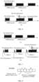
- FIG. 6 (b) after the method in the embodiments of the disclosure is introduced, before a timeout expires after the on duration timer is started, one piece of second information is transmitted, and data arriving with lag are notified by using the second information.
- FIG. 6 (b) when the second information is transmitted, the data arrive with lag, and then a timer may be started. The timer is represented by a new timer in the figure.
- the second information is not transmitted when no data lag occurs, and is transmitted when data lag occurs.
- the new timer herein may be a new timer or an existing timer triggered by the second DCI.
- the first timer may be a drx-RetransferssionTimerDL, may be a timer started according to the configuration parameter of the CDRX indicated by the second DCI, or may be a second timer triggered by the third DCI. That is, as shown in FIG. 6 (b) , a second CDRX period includes a new timer.
- the UE monitors the PDCCH.
- FIG. 7 is a schematic diagram comparing yet another method for discontinuous reception and a conventional CDRX method according to an embodiment of the disclosure.
- FIG. 7 mainly shows an example in which cases of arrival ahead of time and arrival with lag are both processed, that is, a case that the indication information includes the first information and the second information in the method shown in FIG. 3 , and a case that the method shown in FIG. 4 includes S401 to S404.
- FIG. 7 is mainly described by using an example in which the first information is periodically transmitted, but it is not limited that the first information needs to be periodically transmitted.
- the network device may not transmit the first information when the data are not arrived ahead of time. In this case, if no first information is decoded by the UE, it is considered by default that the data do not arrive ahead of time.
- the first information is periodically transmitted. Whether the data arrive ahead of time is notified by using the first information, and the second information is transmitted when data lag occurs.
- first information-1 when first information-1 is transmitted, the data arrive ahead of time, and an offset standard value may be reduced to offset 1, that is, the on duration timer is started ahead of time. Monitoring is performed by using a dense SSSG during the on duration timer.
- density of white lines in a black box is denser during on duration timer 1 in the figure, and the time length of the on duration timer is shortened, that is, on duration timer 1 is shorter.
- first information-2 is transmitted, the data normally arrive, and default offset, that is, offset 2, may be used.
- the on duration timer is normally started. Monitoring is performed by using a sparse SSSG during the on duration timer. That is, density of white lines in a black box during on duration timer 2 in the figure is default density.
- first information-3 is transmitted, the data do not arrive ahead of time, and default offset, that is, offset 3 (offset 2 is equal to offset 3) is used.
- the on duration timer is normally started.
- one piece of second information is transmitted, and data arriving with lag are notified by using the second information.
- the second information is transmitted, the data arrive with lag.
- a new timer is started. That is, as shown in FIG. 7 (b) , in the last longest timer, the UE continuously monitors the PDCCH.
- FIG. 8 is a schematic structural diagram of first DCI according to an embodiment of the disclosure.
- an i1 th bit of the first DCI is used for indicating whether data arrive ahead of time. For example, 1 may correspond to being ahead of time, and 0 may correspond to not being ahead of time. That is to say, when a value of the i1 th bit is 1, it indicates that the data arrive ahead of time. When the value of the i1 th bit is 0, it indicates that the data do not arrive ahead of time.
- the i1 th bit may be considered as an example of the first preset bit. As shown in FIG.
- some or all of a total of N-1 bits from an i2 th bit to an iN th bit of the first DCI may be used for indicating at least one parameter of the configuration parameters of the CDRX or indicating an identifier of a parameter set of the configuration parameters of the CDRX. That is, at least one bit (some or all of a total of N-1 bits from an i2 th bit to an iN th bit being used as an example herein) other than the first preset bit (the i1 th bit being used as an example herein) in the above first DCI is used for indicating at least one configuration parameter of the CDRX or indicating a identifier of a parameter set of the CDRX.
- the N-1 bits may be used for indicating offset, for example, in slot or x milliseconds (x may be a value such as 0.125, and the unit is 0.125 milliseconds), from the first DCI to the on duration timer.
- the N-1 bits may represent a unit length of 1 to 32.
- three bits in the N-1 bits may be used to indicate an identifier of a used parameter set of the CDRX. For example, a value of the three bits is 0, indicating a parameter set with an index being 0.
- bits in the N-1 bits may be used to indicate offset, and one bit in the N-1 bits may be used to indicate a density identifier of the SSSG.
- the SSSG is sparse at other time, and the SSSG is changed to be dense only when the data are ahead, that is, the first bit is 1.
- three bits in the N-1 bits may be used to indicate the offset, and two bits in the N-1 bits may be used to indicate the identifier of the used SSSG.
- a plurality of SSSGs are preconfigured by the RRC and are distinguished through identifiers. It should be understood that the values in the foregoing examples are merely for ease of understanding the solutions, and do not limit the solutions. Those skilled in the art may select values according to requirements.
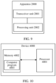
- FIG. 9 is a schematic diagram of an apparatus for discontinuous reception according to an embodiment of the disclosure.
- the apparatus 2000 includes a transceiver unit 2001 and a processing unit 2002.
- the apparatus 2000 may be integrated into user equipment or a network device.
- the apparatus 2000 may be configured to perform steps performed by user equipment or a network device in any one of the foregoing methods for discontinuous reception.
- the transceiver unit 2001 may be configured to perform S301
- the processing unit 2002 may be configured to perform S302.
- the transceiver unit 2001 may be configured to perform S401 and S403, and the processing unit 2002 may be configured to perform S402 and S404.
- the apparatus 2000 may further include a storage unit for storing relevant data.
- the storage unit may be integrated in the processing unit 2002, or may be a unit independent of the transceiver unit 2001 and the processing unit 2002.
- FIG. 10 is a schematic diagram of a hardware structure of an electronic device according to an embodiment of the disclosure.
- the electronic device 4000 includes: at least one processor 4001 (only one processor is shown in FIG. 10 ), a memory 4002, and a computer program 4003 stored in the memory 4002 and capable of being run on the at least one processor 4001.
- the processor 4001 implements steps of any one of the foregoing methods when executing the computer program 4003.
- FIG. 10 is only an example of the electronic device, and does not constitute a limitation on the electronic device.
- the electronic device may include more or less components than those shown in the figure, or combine some components or different components, for example, may further include an input/output device, a network access device, etc.
- the processor 4001 may be a central processing unit (CPU), another general-purpose processor, a digital signal processor (DSP), an application specific integrated circuit (ASIC), a field-programmable gate array (FPGA), or another programmable logic device, a discrete gate or transistor logic device, or a discrete hardware component.
- the general-purpose processor may be a microprocessor, or the processor may be any conventional processor or the like.
- the memory 4002 may be an internal storage unit of the electronic device 4000, for example, a hard disk or memory of the electronic device 4000. In some other embodiments, the memory 4002 may alternatively be an external storage device of the electronic device 4000, for example, a plug-in hard disk, a smart media card (SMC), a secure digital (SD) card, or a flash card arranged on the electronic device 4000. Optionally, the memory 4002 may further include both the internal storage unit and the external storage device of the electronic device 4000.
- the memory 4002 is configured to store an operating system, an application program, a bootloader, data, and other programs, for example, a program code of the computer program.
- the memory 4002 may be further configured to temporarily store data that has been output or data to be output.
- the embodiments of the disclosure further provide an electronic device.
- the electronic device includes: at least one processor, a memory, and a computer program stored in the memory and capable of being run on the at least one processor.
- the processor executes the computer program, the electronic device is caused to implement the steps of any of the above method embodiments.
- the electronic device may be user equipment, and is configured to perform steps performed by the user equipment, for example, configured to receive indication information and monitor a PDCCH according to the indication information.
- the electronic device may alternatively be a network device, and is configured to perform steps performed by the network device, for example, configured to generate and transmit indication information.
- the embodiments of the disclosure further provide a computer-readable storage medium.
- the computer-readable storage medium stores a computer program.
- the computer program may implement steps of any one of the above method embodiments when executed by an electronic device.
- the embodiments of the disclosure further provide a chip.
- the chip includes a processor.
- the processor is configured to read and perform a computer program stored in a memory.
- an electronic device where the chip is located may implement steps of any one of the above method embodiments.
- the chip further includes a memory, and the memory is electrically connected to the processor.
- the chip may further include a communication interface.
- the embodiments of the disclosure also provide a computer program product.
- the computer program product includes a computer program.
- the computer program may implement steps of the above method embodiments when executed by an electronic device.
- the integrated unit When the integrated unit is implemented in the form of a software functional unit and sold or used as an independent product, the integrated unit may be stored in a computer-readable storage medium. Based on such understanding, all or some of procedures of the method in the foregoing embodiments of the disclosure may be implemented by a computer program instructing relevant hardware.
- the computer program may be stored in a computer-readable storage medium. When the computer program is executed, the steps of the above method embodiments may be implemented.
- the computer program includes a computer program code.
- the computer program code may be in a source code form, an object code form, an executable file, some intermediate forms, or the like.
Landscapes
- Engineering & Computer Science (AREA)
- Computer Networks & Wireless Communication (AREA)
- Signal Processing (AREA)
- Mobile Radio Communication Systems (AREA)
Applications Claiming Priority (2)
| Application Number | Priority Date | Filing Date | Title |
|---|---|---|---|
| CN202211166990.7A CN117812671A (zh) | 2022-09-23 | 2022-09-23 | 非连续接收的方法及装置 |
| PCT/CN2023/114371 WO2024060913A1 (zh) | 2022-09-23 | 2023-08-23 | 非连续接收的方法及装置 |
Publications (2)
| Publication Number | Publication Date |
|---|---|
| EP4580261A1 true EP4580261A1 (de) | 2025-07-02 |
| EP4580261A4 EP4580261A4 (de) | 2025-12-24 |
Family
ID=90427148
Family Applications (1)
| Application Number | Title | Priority Date | Filing Date |
|---|---|---|---|
| EP23867206.7A Pending EP4580261A4 (de) | 2022-09-23 | 2023-08-23 | Verfahren und vorrichtung für diskontinuierlichen empfang |
Country Status (3)
| Country | Link |
|---|---|
| EP (1) | EP4580261A4 (de) |
| CN (2) | CN117812671A (de) |
| WO (1) | WO2024060913A1 (de) |
Family Cites Families (7)
| Publication number | Priority date | Publication date | Assignee | Title |
|---|---|---|---|---|
| CN109429258B (zh) * | 2017-07-17 | 2021-10-29 | 中国移动通信有限公司研究院 | 一种信道监听的指示方法、监听方法、终端及网络侧设备 |
| WO2019183848A1 (zh) * | 2018-03-28 | 2019-10-03 | Oppo广东移动通信有限公司 | 监听pdcch的方法、终端设备和网络设备 |
| CN113597812A (zh) * | 2019-03-26 | 2021-11-02 | Oppo广东移动通信有限公司 | Pdcch监听方法、终端设备和网络设备 |
| CN111278096B (zh) * | 2020-01-21 | 2023-07-04 | 展讯通信(上海)有限公司 | 信道监听的指示方法、装置及存储介质 |
| WO2021217344A1 (zh) * | 2020-04-27 | 2021-11-04 | Oppo广东移动通信有限公司 | 一种信道监听方法、电子设备及存储介质 |
| US20220232477A1 (en) * | 2021-01-15 | 2022-07-21 | Qualcomm Incorporated | Downlink traffic jitter handling for xr ue power saving |
| CN117202324A (zh) * | 2021-01-18 | 2023-12-08 | 大唐移动通信设备有限公司 | Dci的发送方法、接收方法、装置、网络侧设备及终端 |
-
2022
- 2022-09-23 CN CN202211166990.7A patent/CN117812671A/zh active Pending
-
2023
- 2023-08-23 WO PCT/CN2023/114371 patent/WO2024060913A1/zh not_active Ceased
- 2023-08-23 CN CN202380062153.6A patent/CN119744558A/zh active Pending
- 2023-08-23 EP EP23867206.7A patent/EP4580261A4/de active Pending
Also Published As
| Publication number | Publication date |
|---|---|
| EP4580261A4 (de) | 2025-12-24 |
| CN117812671A (zh) | 2024-04-02 |
| WO2024060913A1 (zh) | 2024-03-28 |
| CN119744558A (zh) | 2025-04-01 |
Similar Documents
| Publication | Publication Date | Title |
|---|---|---|
| EP3963953B1 (de) | Bestimmung der pdcch-überwachung während der einschaltdauer im energiesparmodus | |
| CN116321513B (zh) | 用于执行随机接入信道进程的方法及其用户设备 | |
| EP3996427B1 (de) | Verfahren und vorrichtung zur erkennung eines aufwecksignals | |
| US12363637B2 (en) | Terminal device wakeup method and apparatus, network device, and terminal device | |
| EP3972352B1 (de) | Verfahren und vorrichtung zur suchraumüberwachung | |
| EP4017128A1 (de) | Energiesparverfahren für endgerät, energiesparvorrichtung, informationssendeverfahren und vorrichtung, speichermedium und elektronische vorrichtung | |
| CN114424482B (zh) | 通信方法及装置 | |
| CN114765896A (zh) | Msg3传输方法、装置、设备及存储介质 | |
| JP7241857B2 (ja) | 信号監視方法及び装置 | |
| EP3565326B1 (de) | Kommunikationsverfahren und netzwerkvorrichtung | |
| CN111865536B (zh) | 搜索空间的监测、配置方法及装置 | |
| US11616625B2 (en) | Wireless communication method, terminal, and network device | |
| EP2830378A1 (de) | Ressourcenzuweisungsanzeigeverfahren, ressourcenzuweisungsverfahren und vorrichtung | |
| EP3281462B1 (de) | Methoden, drahtloses kommunikationsgerät und funknetzwerkknoten zur paging verwaltung | |
| EP4009713A1 (de) | Kommunikationsverfahren und -vorrichtung | |
| EP4529293A2 (de) | Verfahren und vorrichtung zur überwachung eines physikalischen downlink-steuerkanals (pdcch) und endgerät | |
| WO2021114060A1 (zh) | 通信方法及相关装置、设备 | |
| EP3729898A1 (de) | Verwaltung von blinden pdcch-suchen in einem unlizenzierten bandszenario in new radio | |
| EP3621399A1 (de) | Verfahren und vorrichtung zum senden einer direktzugriffsantwortnachricht, verfahren und vorrichtung zum empfangen einer direktzugriffsantwortnachricht | |
| JP2023512807A (ja) | 無線通信において、低減した能力のデバイスをサポートする方法及び装置 | |
| EP4387340A1 (de) | Verfahren und vorrichtung zur informationsüberwachung | |
| WO2022012592A1 (zh) | 反馈信息传输方法、装置、终端及网络侧设备 | |
| EP4580261A1 (de) | Verfahren und vorrichtung für diskontinuierlichen empfang | |
| JP7686774B2 (ja) | 物理下りリンク制御チャネル繰り返し伝送方法、装置及びユーザ機器 | |
| CN113904759A (zh) | 控制信息接收方法、控制信息发送方法及相关设备 |
Legal Events
| Date | Code | Title | Description |
|---|---|---|---|
| STAA | Information on the status of an ep patent application or granted ep patent |
Free format text: STATUS: THE INTERNATIONAL PUBLICATION HAS BEEN MADE |
|
| PUAI | Public reference made under article 153(3) epc to a published international application that has entered the european phase |
Free format text: ORIGINAL CODE: 0009012 |
|
| STAA | Information on the status of an ep patent application or granted ep patent |
Free format text: STATUS: REQUEST FOR EXAMINATION WAS MADE |
|
| 17P | Request for examination filed |
Effective date: 20250328 |
|
| AK | Designated contracting states |
Kind code of ref document: A1 Designated state(s): AL AT BE BG CH CY CZ DE DK EE ES FI FR GB GR HR HU IE IS IT LI LT LU LV MC ME MK MT NL NO PL PT RO RS SE SI SK SM TR |
|
| A4 | Supplementary search report drawn up and despatched |
Effective date: 20251126 |
|
| RIC1 | Information provided on ipc code assigned before grant |
Ipc: H04W 52/02 20090101AFI20251120BHEP Ipc: H04W 76/28 20180101ALI20251120BHEP |
|
| DAV | Request for validation of the european patent (deleted) | ||
| DAX | Request for extension of the european patent (deleted) |