EP4580253A1 - Verfahren und vorrichtung zur unterstützung der synchronisation eines uplink-signals in einem drahtloskommunikationssystem - Google Patents
Verfahren und vorrichtung zur unterstützung der synchronisation eines uplink-signals in einem drahtloskommunikationssystem Download PDFInfo
- Publication number
- EP4580253A1 EP4580253A1 EP23873230.9A EP23873230A EP4580253A1 EP 4580253 A1 EP4580253 A1 EP 4580253A1 EP 23873230 A EP23873230 A EP 23873230A EP 4580253 A1 EP4580253 A1 EP 4580253A1
- Authority
- EP
- European Patent Office
- Prior art keywords
- cell
- information
- base station
- random access
- handover
- Prior art date
- Legal status (The legal status is an assumption and is not a legal conclusion. Google has not performed a legal analysis and makes no representation as to the accuracy of the status listed.)
- Pending
Links
Images


Classifications
-
- H—ELECTRICITY
- H04—ELECTRIC COMMUNICATION TECHNIQUE
- H04W—WIRELESS COMMUNICATION NETWORKS
- H04W36/00—Hand-off or reselection arrangements
- H04W36/0005—Control or signalling for completing the hand-off
- H04W36/0055—Transmission or use of information for re-establishing the radio link
- H04W36/0058—Transmission of hand-off measurement information, e.g. measurement reports
-
- H—ELECTRICITY
- H04—ELECTRIC COMMUNICATION TECHNIQUE
- H04W—WIRELESS COMMUNICATION NETWORKS
- H04W36/00—Hand-off or reselection arrangements
-
- H—ELECTRICITY
- H04—ELECTRIC COMMUNICATION TECHNIQUE
- H04W—WIRELESS COMMUNICATION NETWORKS
- H04W36/00—Hand-off or reselection arrangements
- H04W36/0005—Control or signalling for completing the hand-off
- H04W36/0055—Transmission or use of information for re-establishing the radio link
- H04W36/0072—Transmission or use of information for re-establishing the radio link of resource information of target access point
- H04W36/00725—Random access channel [RACH]-less handover
-
- H—ELECTRICITY
- H04—ELECTRIC COMMUNICATION TECHNIQUE
- H04W—WIRELESS COMMUNICATION NETWORKS
- H04W36/00—Hand-off or reselection arrangements
- H04W36/0005—Control or signalling for completing the hand-off
- H04W36/0055—Transmission or use of information for re-establishing the radio link
- H04W36/0077—Transmission or use of information for re-establishing the radio link of access information of target access point
-
- H—ELECTRICITY
- H04—ELECTRIC COMMUNICATION TECHNIQUE
- H04W—WIRELESS COMMUNICATION NETWORKS
- H04W36/00—Hand-off or reselection arrangements
- H04W36/0005—Control or signalling for completing the hand-off
- H04W36/0083—Determination of parameters used for hand-off, e.g. generation or modification of neighbour cell lists
- H04W36/0085—Hand-off measurements
-
- H—ELECTRICITY
- H04—ELECTRIC COMMUNICATION TECHNIQUE
- H04W—WIRELESS COMMUNICATION NETWORKS
- H04W36/00—Hand-off or reselection arrangements
- H04W36/08—Reselecting an access point
-
- H—ELECTRICITY
- H04—ELECTRIC COMMUNICATION TECHNIQUE
- H04W—WIRELESS COMMUNICATION NETWORKS
- H04W56/00—Synchronisation arrangements
-
- H—ELECTRICITY
- H04—ELECTRIC COMMUNICATION TECHNIQUE
- H04W—WIRELESS COMMUNICATION NETWORKS
- H04W56/00—Synchronisation arrangements
- H04W56/001—Synchronization between nodes
-
- H—ELECTRICITY
- H04—ELECTRIC COMMUNICATION TECHNIQUE
- H04W—WIRELESS COMMUNICATION NETWORKS
- H04W56/00—Synchronisation arrangements
- H04W56/004—Synchronisation arrangements compensating for timing error of reception due to propagation delay
- H04W56/0045—Synchronisation arrangements compensating for timing error of reception due to propagation delay compensating for timing error by altering transmission time
Definitions
- the disclosure relates generally to a wireless communication system and, more specifically, to a method and an apparatus for transmitting and receiving a signal to support synchronization of an uplink signal before performing handover.
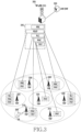
- 6G communication systems which are expected to be implemented approximately by 2030, will have a maximum transmission rate of tera (i.e., 1,000 giga)-level bps and a radio latency of 100 ⁇ sec. That is, 6G communication systems will be 50 times as fast as 5G communication systems and have the 1/10 radio latency thereof.
- the functions of the NR gNB 305 and the TRPs may be configured by separating each layer from the PDCP/RLC/MAC/PHY layers such as 345.
- the TRP may have only the PHY layer and perform the function of the corresponding layer (315, 325), the TRP may have only the PHY layer and the MAC layer and perform the functions of the corresponding layers (310, 335, 340), and the TRP may have only the PHY layer, the MAC layer, and the RLC layer and perform the functions of the corresponding layers (320, 330).
- the TRP may include structures 315 and 325 having only the PHY layer and capable of performing the function of the corresponding layer.
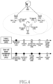
- FIG. 4 illustrates a scenario in which a UE connected to a serving cell transmits/receives data through a beam from a transmission reception point (TRP) of a target cell according to various embodiments of the disclosure.
- FIG. 4 illustrates a scenario for inter-cell beam management according to an embodiment, in which a UE transmits/receives data through a beam of a TRP of a neighboring cell supporting beam change based on L1/L2 while maintaining a connection state with the serving cell.
- a cell with which the UE currently maintains a connection state may be referred to as a serving cell
- a cell to which the handover is to be performed may be referred to as a target cell.
- a neighboring cell or other cell other than the serving cell may include a target cell to which the UE is to perform the handover.
- a plurality of cells (TRP1-Cell1, TRP2-Cell2) 410 and 415 exist in a single distributed unit (DU) 405, various embodiments of the disclosure may be applied to the case of inter-DU (e.g., each DU includes one TRP-Cell).
- a cell which is not a serving cell supporting L1/L2-based mobility (e.g., beam change and serving cell change) may include a neighbor cell, a non-serving cell, or an additional cell with the physical cell identity (PCI) different from the serving cell.
- PCI physical cell identity
- the UE 420 may transmit/receive data in a connected state through TRP 1 410 of the serving cell 1, and may use TCI state 1 425 or 430 which is the optimal beam.
- the UE may receive, from the serving cell 410, configuration information for L3 channel measurement (radio resource management (RRM)) for the additional cell (TRP 2-Cell 2) 415 with the different PCI from the serving cell, based on received RRC configuration information, and perform an L3 measurement operation 446 on the received frequency and cell.
- RRM radio resource management
- the serving cell (TRP 1-Cell 1) 410 may indicate a handover to another cell (TRP 2-Cell 2) 415 based on the reported measurement value (indicated by reference numeral 447), and when the handover may be completed, additional RRC configuration information may be transferred to the UE 420 through TRP 2-Cell 2 415 (indicated by reference numeral 448).
- the additional RRC configuration information may include UL/DL configuration information in the corresponding cell and L1 measurement-related configuration (CSI-RS measurement and reporting), and particularly may include TCI state configuration information for the physical downlink control channel (PDCCH) and the physical downlink shared channel (PDSCH) channel.
- the UE 420 may perform L1 measurement according to configuration (indicated by reference numeral 449), and the base station may update the TCI state through L1/L2 signaling according to the measurement report (indicated by reference numeral 450).
- TCI state 2 440 which is an optimal beam, may be indicated.
- the serving cell may be Cell 1 and, after the handover, Cell 2 may be the serving cell. Accordingly, many procedures and times are required even after handover until the optimal beam is indicated.
- an enhanced beam change scheme 455 may include the content as follows.
- the UE may receive, from the serving cell, a beam configuration associated with the additional cell (TRP 2-Cell 2) 415 having different PCI from the serving cell, based on the RRC configuration information 456 received from the serving cell 410.
- the beam configuration associated with the additional cell (TRP 2-Cell 2) 415 with the different PCI from the serving cell i.e., the part of associating the TCI state corresponding to TRP2
- a unified TCI state framework may be applied for beam management between the corresponding cells.
- the unified TCI state framework may be configured as one of a joint UL/DL mode and a separate UL/DL mode as applying a common TCI state framework in uplink, downlink, a common channel, and a dedicated channel.
- the UE may perform the L1 measurement on the TRP 2-Cell 2 according to the configuration and report the measurement result to the serving cell (Cell 1) 410 (indicated by reference numeral 457).
- the serving cell may trigger a beam change and indicate the beam change to the UE through L1/L2 signaling (indicated by reference numeral 458).
- the UE 420 may change the beam to a specific beam (TCI state 2) 440 of TRP 2 (Cell 2) 415 based on the corresponding indication, and perform a physical channel establishment and higher layer establishment operation associated with the configured beam.
- TCI state 2 TCP 2
- the UE may perform data transmission/reception using the channel link of TRP 2 (Cell 2) 415 (PDCCH/PDSCH reception, PUCCH/PUSCH transmission).
- the UE may perform transmission/reception of the common control channel through the serving cell (Cell 1) 410.
- the UE may perform the L3 measurement operation based on the measurement configuration configured in the independent serving cell (indicated by reference numeral 459), receive a handover command message from the serving base station (Cell 1), and change the serving cell to Cell 2 (indicated by reference numeral 460).
- the UE may perform data transmission/reception to/from a specific TRP 2 of Cell 2 supporting L1/L2-based mobility in a state of being connected to the serving cell, and may continuously use the corresponding beam even after handover.
- the RRC configurations for the configurations and operations related to the L1 measurement and report in operation 457 specifically include the following.
- the following content is basically applied to the following embodiments of the disclosure, and an enhancement scheme may be added in the following embodiments.
- FIG. 5 illustrates a scenario in which a UE changes a beam to a beam of a target cell and a TRP of the target cell according to various embodiments of the disclosure.
- FIG. 5 illustrates a scenario in which a UE transmits/receives data by changing a serving cell and a beam to a TRP of a cell supporting beam change based on L1/L2 according to various embodiments of the disclosure.
- FIG. 5 illustrates a scenario in which a UE transmits/receives data by changing a serving cell and a beam to a TRP of a cell supporting beam change based on L1/L2 according to various embodiments of the disclosure.
- the enhanced beam change scheme 525 or 575 considered in various embodiments described with reference to FIG. 5 are as follows.
- the UE may, based on RRC configuration information from the serving cell 510, receive common configuration and dedicated configuration information about the additional cell (TRP 2-Cell 2) 515 with the different PCI from the serving cell (indicated by reference numeral 526). For example, configuration information corresponding to ServingCellConfigCommon and ServingCellConfig, ServingCellID or candidateCellID (cell ID associated with the PCI), may be provided in advance.
- the configuration information received by the UE may be provided in the form of pre-configuration in RRC configuration, and configuration information for a plurality of cells may be included.
- the configuration information received by the UE may include all pieces of configuration information (cell configuration, bearer configuration, security key configuration, etc.) applied when the UE moves to another cell (handover).
- the configuration information received by the UE may include the unified TCI state configuration described in operation 456 and configurations related to the L1 measurement and report.
- the situations disclosed in FIG. 5 may include a specific method for a structure for previously providing a configuration for candidate neighbor cells where L1/L2 handover may be performed, an operation in which the configuration information is optionally applied after handover in L1/L2 signaling, and an L1/L2 beam change and cell change (handover).
- the UE may perform L1 measurement on the TRP 2-Cell 2 515 according to the configuration received in operation 527 and report the measurement result to the serving cell (Cell 1) 510.
- the serving cell may trigger a beam change in operation 528 and indicate the beam change to the UE through L1/L2 signaling.
- the UE may perform beam change to TRP 2 (Cell 2) 515 based on the received indication and transmit/receive data through the TRP 2 (Cell 2) 515.
- the serving cell is not changed, and the UE may still be RRC connected to the serving cell (Cell 1) 510. Thereafter, the UE still performs the L1 measurement on the TRP 2-Cell 2 515 and reports the measurement result to the serving cell (Cell 1) 510.
- the serving cell (Cell 1) 510 may indicate handover to the UE when the L1 measurement reported by the UE satisfies a triggering condition for the handover to the TRP 2-Cell 2 515.
- the handover indication of the serving cell (Cell 1) 510 may be transmitted based on the L1/L2 message. For example, an indicator indicating handover may be included in the MAC CE or DCI. According to embodiments based on Case 1, an operation of matching uplink synchronization with respect to a target cell by the UE before performing handover to the target cell by receiving a handover message may be included.
- the UE may receive common configuration and dedicated configuration information for the additional cell (TRP 2-Cell 2) 545 having different PCI from the serving cell 540 through RRC configuration information (indicated by reference numeral 576).
- RRC configuration information indicated by reference numeral 576.
- configuration information corresponding to ServingCellConfigCommon and ServingCellConfig, ServingCellID or candidateCellID (cell ID associated with the PCI) may be provided in advance.
- the corresponding configuration information may be provided in the form of pre-configuration in RRC configuration, and may include configuration information for a plurality of cells. Further, the corresponding configuration may include all pieces of configuration information (e.g., cell configuration, bearer configuration, security key configuration, etc.) applied when the UE moves to the corresponding cell (handover).
- the corresponding configuration may include the unified TCI state configuration described in operation 456 and configurations related to the L1 measurement and report. According to embodiments based on Case 2, an operation of matching uplink synchronization with respect to the target cell by the UE before performing handover to the target cell by receiving a handover message may be included.
- the UE may perform L1 measurement on the TRP 2-Cell 2 545 according to the configuration received in operation 577 and report the measurement result to the serving cell (Cell 1) 540.
- the serving cell may trigger a beam change and handover in operation 578 and indicate, to the UE, the beam change and handover through L1/L2 signaling.
- the UE may perform handover simultaneously with beam change to TRP 2 (Cell 2) 515 based on the received indication and transmit/receive data through the corresponding TRP 2 (Cell 2) 515.
- the UE may apply the configuration information for the target cell where handover is performed, as preconfigured in operation 576.
- the UE may perform random access or may omit random access to the target cell.
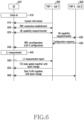
- FIG. 6 illustrates a signal flow for inter-cell beam management according to various embodiments of the disclosure.
- the UE 601 may receive system information from cell 1 602 in a camp-on state 610 (operation 615). After receiving the system information, the UE may perform a transition procedure to the RRC connected state (operation 620).
- the serving cell 602 may request a UE capability (UE capability enquiry message) from the UE, and the UE may transfer information on the UE capability (UE capability information message) according to a request of base station request (operation 625).
- the information on the UE capability may include information on whether to support L1/L2-based inter-cell beam change/management and handover.
- the UE may transfer the information on the UE capability through signaling of at least one of UE-specific capability, band-specific capability, or band combination-specific capability.
- the serving cell 602 may request, from neighboring cell 2 603 that supports L1/L2-based mobility, the configuration information required when the UE performs beam change and handover based on L1/L2 (operation 625).
- the cell 2 603 may include the relevant configuration information in a response message with respect to the request from the serving cell and transfer the response message (operation 630).
- operations 630 and 635 may be omitted in network implementations where cell 1 602 and cell 2 603 reside within a single DU (intra-DU scenario).
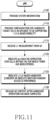
- the target cell to which the handover is performed matches the current serving cell in terms of uplink synchronization, and the target cell and the current serving cell may belong to the same DU.
- the base station may indicate the corresponding operation on the assumption that the target cell and the serving cell are synchronized, and in this case, the UE may apply the uplink synchronization from the serving cell as it is.
- the base station receives an L1 measurement value from the UE, and in this case, the measurement value may be a non-serving cell that supports L1/L2-based mobility (handover).
- the serving cell may determine whether to change the beam of the UE based on the received measurement result.
- the base station may indicate a cell change and a beam change of the UE via L1/L2 signaling.
- the L1/L2 signaling described above may include a MAC CE or DCI, and may include information indicating the change to a specific beam of a neighboring cell.
- the base station may also simultaneously indicate via L1/L2 signaling in the corresponding operation whether to perform random access to the cell in which the handover occurs and whether to perform an L2 reset (MAC reset, RLC/PDCP reestablishment).
- the serving cell performs the handover procedure and may delete the UE context and release the connection when the handover to the target cell is complete.
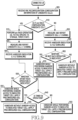
- the measurement value relating to whether a handover is determined may include L1 measurement.
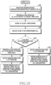
- the base station may transfer a signal indicating an uplink synchronization between the UE and the candidate target cell.
- the corresponding signal may be newly transferred as an RRC message, and may include information indicating to perform pre-RACH for a corresponding candidate target cell by introducing a new MAC CE (with new LCID) and a DCI message.
- the UE may re-perform the pre-RACH operation for the corresponding target cell described in operation 1030.
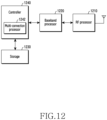
- FIG. 12 illustrates a functional structure of a UE according to various embodiments of the disclosure.
- the RF processor 1210 may perform a function for transmitting and receiving a signal via a wireless channel, such as band conversion and amplification of the signal. That is, the RF processor 1210 may up-convert a baseband signal provided from the baseband processor 1220 to an RF band signal, may transmit the same through an antenna, and may down-convert an RF band signal received through the antenna to a baseband signal.
- the RF processor 1210 may include a transmission filter, a reception filter, an amplifier, a mixer, an oscillator, a digital-to-analog converter (DAC), an analog-to-digital converter (ADC), and the like.
- the UE may include multiple antennas.
- the RF processor 1210 may include multiple RF chains. Furthermore, the RF processor 1210 may perform beamforming. For the beamforming, the RF processor 1210 may adjust the phase and magnitude of each of signals transmitted and received through multiple antennas or antenna elements. In addition, the RF processor may perform MIMO, and may receive multiple layers when performing a MIMO operation.
- the baseband processor 1220 may perform functions of conversion between baseband signals and bitstrings according to the system's physical layer specifications. For example, during data transmission, the baseband processor 1220 may encode and modulate a transmitted bitstring to generate complex symbols. In addition, during data reception, the baseband processor 1220 may demodulate and decode a baseband signal provided from the RF processor 1210 to restore a received bitstring. For example, when following the orthogonal frequency division multiplexing (OFDM) scheme, during data transmission, the baseband processor 1220 may encode and modulate a transmitted bitstring to generate complex symbols, may map the complex symbols to subcarriers, and may configure OFDM symbols through an inverse fast Fourier transform (IFFT) operation and cyclic prefix (CP) insertion.
- OFDM orthogonal frequency division multiplexing
- the baseband processor 1220 may split a baseband signal provided from the RF processor 1210 at the OFDM symbol level, may restore signals mapped to subcarriers through a fast Fourier transform (FFT) operation, and may restore a received bitstring through demodulation and decoding.
- FFT fast Fourier transform
- the baseband processor 1220 and the RF processor 1210 may transmit and receive signals as described above. Therefore, the baseband processor 1220 and the RF processor 1210 may be referred to as a transmitter, a receiver, a transceiver, or a communication unit. Furthermore, at least one of the baseband processor 1220 and the RF processor 1210 may include multiple communication modules to support multiple different radio access technologies. In addition, at least one of the baseband processor 1220 and the RF processor 1210 may include different communication modules to process signals in different frequency bands.
- the different radio access technologies may include wireless LANs (for example, IEEE 802.11), cellular networks (for example, LTE), and the like.
- the different frequency bands may include super high frequency (SHF) (e.g., 2 NRHz) bands and millimeter wave (mmWave) (e.g., 60GHz) bands.
- SHF super high frequency
- mmWave millimeter wave
- the storage 1230 stores data such as basic programs, application programs, and configuration information for operations of the UE.
- the storage 1230 may store information related to the second access node, which performs wireless communication using the second wireless access technology.
- the storage 1230 provides the stored data at the request of the controller 1240.
- the controller 1240 controls the overall operation of the UE.
- the controller 1240 may transmit/receive signals through the baseband processor 1220 and the RF processor 1210.
- the controller 1240 records data in the storage 1230 and reads the data from the storage 1230.
- the controller 1240 may include at least one processor.
- the controller 1240 may include a communication processor (CP) configured to perform control for communication, and an application processor (AP) configured to control upper layers such as application programs.
- CP communication processor
- AP application processor
- FIG. 13 illustrates a functional structure of a base station according to various embodiments of the disclosure.
- the base station may include an RF processor 1310, a baseband processor 1320, a backhaul communication unit 1330, a storage 1340, and a controller 1350.
- the RF processor 1310 may perform a function for transmitting and receiving a signal via a wireless channel, such as band conversion and amplification of the signal. That is, the RF processor 1310 may up-convert a baseband signal provided from the baseband processor 1320 to an RF band signal, may transmit the same through an antenna, and may down-convert an RF band signal received through the antenna to a baseband signal.
- the RF processor 1310 may include a transmission filter, a reception filter, an amplifier, a mixer, an oscillator, a DAC, and an ADC. Referring to FIG. 13 , although only one antenna is illustrated, the first access node may include multiple antennas. In addition, the RF processor 1310 may include multiple RF chains.
- the RF processor 1310 may perform beamforming. For the beamforming, the RF processor 1310 may adjust the phase and magnitude of each of signals transmitted and received through multiple antennas or antenna elements. The RF processor may perform down-MIMO operations by transmitting one or more layers.
- the baseband processor 1320 may perform functions of conversion between baseband signals and bitstrings according to the physical layer specifications of a first radio access technology. For example, during data transmission, the baseband processor 1320 may encode and modulate a transmitted bitstring to generate complex symbols. In addition, during data reception, the baseband processor 1320 may demodulate and decode a baseband signal provided from the RF processor 1310 to restore a received bitstring. For example, when following the OFDM scheme, during data transmission, the baseband processor 1320 may encode and modulate a transmitted bitstring to generate complex symbols, may map the complex symbols to subcarriers, and may configure OFDM symbols through an IFFT operation and CP insertion.
- the baseband processor 1320 may split a baseband signal provided from the RF processor 1310 at the OFDM symbol level, may restore signals mapped to subcarriers through FFT operation, and may restore a received bitstring through demodulation and decoding.
- the baseband processor 1320 and the RF processor 1310 may transmit and receive signals as described above. Therefore, the baseband processor 1320 and the RF processor 1310 may be referred to as a transmitter, a receiver, a transceiver, a communication unit, or a wireless communication unit.
- the backhaul communication unit 1330 may provide an interface for communicating with other nodes in the network. That is, the backhaul communication unit 1330 converts bitstrings transmitted from the main base station to other nodes, for example, an auxiliary base station, a core network, etc., into physical signals, and converts physical signals received from the other nodes into bitstrings.
- the storage 1340 may store data such as basic programs for operation of the main base station, application programs, and configuration information. In particular, the storage 1340 may store information on bearers allocated to the connected UE, measurement results reported from the connected UE, and the like. In addition, the storage 1340 may store information serving as a criterion for determining whether to provide or stop multiple connections to the UE. In addition, the storage 1340 provides stored data at the request of the controller 230.
- the controller 1350 controls the overall operation of the main base station.
- the controller 1350 may transmit/receive signals through the baseband processor 1320 and the RF processor 1310 or through the backhaul communication unit 1330.
- the controller 1350 records data in the storage 1340 and reads the data from the storage 1340.
- the controller 1350 may include at least one processor.
- a computer-readable storage medium for storing one or more programs (software modules) may be provided.
- the one or more programs stored in the computer-readable storage medium may be configured for execution by one or more processors within the electronic device.
- the at least one program includes instructions that cause the electronic device to perform the methods according to various embodiments of the disclosure as defined by the appended claims and/or disclosed herein.
- These programs may be stored in non-volatile memories including a random access memory and a flash memory, a read only memory (ROM), an electrically erasable programmable read only memory (EEPROM), a magnetic disc storage device, a compact disc-ROM (CD-ROM), digital versatile discs (DVDs), or other type optical storage devices, or a magnetic cassette.
- ROM read only memory
- EEPROM electrically erasable programmable read only memory
- CD-ROM compact disc-ROM
- DVDs digital versatile discs
- any combination of some or all of them may form a memory in which the program is stored.
- a plurality of such memories may be included in the electronic device.
- the programs may be stored in an attachable storage device which can access the electronic device through communication networks such as the Internet, Intranet, Local Area Network (LAN), Wide LAN (WLAN), and Storage Area Network (SAN) or a combination thereof.
- a storage device may access the electronic device via an external port.
- a separate storage device on the communication network may access a portable electronic device.
Landscapes
- Engineering & Computer Science (AREA)
- Computer Networks & Wireless Communication (AREA)
- Signal Processing (AREA)
- Mobile Radio Communication Systems (AREA)
Applications Claiming Priority (2)
| Application Number | Priority Date | Filing Date | Title |
|---|---|---|---|
| KR1020220124396A KR20240044878A (ko) | 2022-09-29 | 2022-09-29 | 무선 통신 시스템에서 상향링크 신호의 동기화를 지원하기 위한 방법 및 장치 |
| PCT/KR2023/015069 WO2024072121A1 (ko) | 2022-09-29 | 2023-09-27 | 무선 통신 시스템에서 상향링크 신호의 동기화를 지원하기 위한 방법 및 장치 |
Publications (2)
| Publication Number | Publication Date |
|---|---|
| EP4580253A1 true EP4580253A1 (de) | 2025-07-02 |
| EP4580253A4 EP4580253A4 (de) | 2025-12-17 |
Family
ID=90478703
Family Applications (1)
| Application Number | Title | Priority Date | Filing Date |
|---|---|---|---|
| EP23873230.9A Pending EP4580253A4 (de) | 2022-09-29 | 2023-09-27 | Verfahren und vorrichtung zur unterstützung der synchronisation eines uplink-signals in einem drahtloskommunikationssystem |
Country Status (3)
| Country | Link |
|---|---|
| EP (1) | EP4580253A4 (de) |
| KR (1) | KR20240044878A (de) |
| WO (1) | WO2024072121A1 (de) |
Cited By (1)
| Publication number | Priority date | Publication date | Assignee | Title |
|---|---|---|---|---|
| WO2026010556A1 (en) * | 2024-07-05 | 2026-01-08 | Telefonaktiebolaget Lm Ericsson (Publ) | Uplink synchronization groups in layer 1 /layer 2 triggered mobility |
Families Citing this family (1)
| Publication number | Priority date | Publication date | Assignee | Title |
|---|---|---|---|---|
| GB2641776A (en) * | 2024-06-12 | 2025-12-17 | Nokia Technologies Oy | Method, apparatus and computer program |
Family Cites Families (3)
| Publication number | Priority date | Publication date | Assignee | Title |
|---|---|---|---|---|
| WO2019220211A2 (en) * | 2018-05-18 | 2019-11-21 | Lenovo (Singapore) Pte. Ltd. | Random access skip configuration |
| CN113228716A (zh) * | 2019-10-02 | 2021-08-06 | 三星电子株式会社 | 用于随机接入过程的方法和设备 |
| KR102587704B1 (ko) * | 2020-07-24 | 2023-10-11 | 아서스테크 컴퓨터 인코포레이션 | 무선 통신 시스템에서 이동성 절차를 위한 방법 및 장치 |
-
2022
- 2022-09-29 KR KR1020220124396A patent/KR20240044878A/ko active Pending
-
2023
- 2023-09-27 WO PCT/KR2023/015069 patent/WO2024072121A1/ko not_active Ceased
- 2023-09-27 EP EP23873230.9A patent/EP4580253A4/de active Pending
Cited By (1)
| Publication number | Priority date | Publication date | Assignee | Title |
|---|---|---|---|---|
| WO2026010556A1 (en) * | 2024-07-05 | 2026-01-08 | Telefonaktiebolaget Lm Ericsson (Publ) | Uplink synchronization groups in layer 1 /layer 2 triggered mobility |
Also Published As
| Publication number | Publication date |
|---|---|
| WO2024072121A1 (ko) | 2024-04-04 |
| KR20240044878A (ko) | 2024-04-05 |
| EP4580253A4 (de) | 2025-12-17 |
Similar Documents
| Publication | Publication Date | Title |
|---|---|---|
| US11570615B2 (en) | Method and apparatus for reporting capability of user equipment in wireless communication system | |
| KR20200114445A (ko) | 무선 통신 시스템에서 복수의 빔을 통해 신호를 송수신하는 방법 및 장치 | |
| KR102810779B1 (ko) | 차세대 무선 통신 시스템에서 자동 이웃 관계 형성을 위한 노드 간 협업 방법 | |
| US12250605B2 (en) | Method and device for handing over terminal in wireless communication system using artificial intelligence | |
| US12289786B2 (en) | Method and device for handover in next generation mobile communication system | |
| KR20200073626A (ko) | 차세대 무선 통신 시스템에서 조건부 핸드오버의 실패 타이머 운용방법 | |
| US12507101B2 (en) | Method and device for transmitting and receiving signals in wireless communication system | |
| US20240380728A1 (en) | Method and device for allocating ip address to du in integrated access and backhaul system | |
| US12356271B2 (en) | Device and terminal operation in next generation mobile communication system | |
| EP4580253A1 (de) | Verfahren und vorrichtung zur unterstützung der synchronisation eines uplink-signals in einem drahtloskommunikationssystem | |
| US20250106713A1 (en) | Method and apparatus of performing ue based uplink timing adjustment for layer 1/2 triggered mobility in the next communication systems | |
| CN120642440A (zh) | 用于在无线通信系统中执行切换的方法和设备 | |
| EP4525521A1 (de) | Verfahren und vorrichtung zur verbesserung der schicht-1-messung und -meldung zur unterstützung der schicht-1-basierten interzellenbewegung in einem mobilkommunikationssystem der nächsten generation | |
| US20240276331A1 (en) | Method and apparatus for updating configuration of conditional pscell change in next-generation mobile communication system | |
| US20250031109A1 (en) | Method and device for operating uplink time adjustment timer during l1/l2-based handover in mobile communication system | |
| US12245087B2 (en) | Method and apparatus for performing cell access without random access in next generation wireless communication system | |
| KR20230008501A (ko) | 이동통신 시스템에서 동시에 여러 개의 캐리어에 대한 pdcch 수신 빔을 활성화하는 방법 및 장치 | |
| US20240107387A1 (en) | Method and apparatus for measurement reporting of uncrewed aerial vehicle terminal in non-terrestrial network | |
| US12262205B2 (en) | Method and apparatus for updating security configuration in next-generation wireless communication system | |
| US20250048312A1 (en) | Method and device for presetting assistance data for positioning of terminal in wireless communication system | |
| KR20240147334A (ko) | 차세대 이동 통신 시스템에서 l1/l2 기반의 핸드오버를 위한 기준 셀 설정을 관리하는 방법 및 장치 | |
| US20250338179A1 (en) | Apparatus and method for conditional lower layer triggered mobility in wireless communication system | |
| EP4676114A1 (de) | Verfahren und vorrichtung zur bereitstellung zusätzlicher messinformationen zur trägeraggregation in einem drahtloskommunikationssystem | |
| US20250266883A1 (en) | Method and apparatus for channel state information pre-acquisition | |
| EP4580246A1 (de) | Verfahren und vorrichtung zur durchführung einer frühen messung in einem mobilkommunikationssystem |
Legal Events
| Date | Code | Title | Description |
|---|---|---|---|
| STAA | Information on the status of an ep patent application or granted ep patent |
Free format text: STATUS: THE INTERNATIONAL PUBLICATION HAS BEEN MADE |
|
| PUAI | Public reference made under article 153(3) epc to a published international application that has entered the european phase |
Free format text: ORIGINAL CODE: 0009012 |
|
| STAA | Information on the status of an ep patent application or granted ep patent |
Free format text: STATUS: REQUEST FOR EXAMINATION WAS MADE |
|
| 17P | Request for examination filed |
Effective date: 20250327 |
|
| AK | Designated contracting states |
Kind code of ref document: A1 Designated state(s): AL AT BE BG CH CY CZ DE DK EE ES FI FR GB GR HR HU IE IS IT LI LT LU LV MC ME MK MT NL NO PL PT RO RS SE SI SK SM TR |
|
| A4 | Supplementary search report drawn up and despatched |
Effective date: 20251117 |
|
| RIC1 | Information provided on ipc code assigned before grant |
Ipc: H04W 36/00 20090101AFI20251111BHEP Ipc: H04W 56/00 20090101ALN20251111BHEP |
|
| DAV | Request for validation of the european patent (deleted) | ||
| DAX | Request for extension of the european patent (deleted) |