EP4580246A1 - Verfahren und vorrichtung zur durchführung einer frühen messung in einem mobilkommunikationssystem - Google Patents
Verfahren und vorrichtung zur durchführung einer frühen messung in einem mobilkommunikationssystem Download PDFInfo
- Publication number
- EP4580246A1 EP4580246A1 EP23875243.0A EP23875243A EP4580246A1 EP 4580246 A1 EP4580246 A1 EP 4580246A1 EP 23875243 A EP23875243 A EP 23875243A EP 4580246 A1 EP4580246 A1 EP 4580246A1
- Authority
- EP
- European Patent Office
- Prior art keywords
- idle mode
- information
- message
- base station
- rrc
- Prior art date
- Legal status (The legal status is an assumption and is not a legal conclusion. Google has not performed a legal analysis and makes no representation as to the accuracy of the status listed.)
- Pending
Links
Images


Classifications
-
- H—ELECTRICITY
- H04—ELECTRIC COMMUNICATION TECHNIQUE
- H04W—WIRELESS COMMUNICATION NETWORKS
- H04W76/00—Connection management
- H04W76/20—Manipulation of established connections
- H04W76/27—Transitions between radio resource control [RRC] states
-
- H—ELECTRICITY
- H04—ELECTRIC COMMUNICATION TECHNIQUE
- H04L—TRANSMISSION OF DIGITAL INFORMATION, e.g. TELEGRAPHIC COMMUNICATION
- H04L5/00—Arrangements affording multiple use of the transmission path
- H04L5/003—Arrangements for allocating sub-channels of the transmission path
- H04L5/0053—Allocation of signalling, i.e. of overhead other than pilot signals
-
- H—ELECTRICITY
- H04—ELECTRIC COMMUNICATION TECHNIQUE
- H04W—WIRELESS COMMUNICATION NETWORKS
- H04W24/00—Supervisory, monitoring or testing arrangements
- H04W24/10—Scheduling measurement reports ; Arrangements for measurement reports
-
- H—ELECTRICITY
- H04—ELECTRIC COMMUNICATION TECHNIQUE
- H04W—WIRELESS COMMUNICATION NETWORKS
- H04W48/00—Access restriction; Network selection; Access point selection
- H04W48/08—Access restriction or access information delivery, e.g. discovery data delivery
-
- H—ELECTRICITY
- H04—ELECTRIC COMMUNICATION TECHNIQUE
- H04W—WIRELESS COMMUNICATION NETWORKS
- H04W48/00—Access restriction; Network selection; Access point selection
- H04W48/18—Selecting a network or a communication service
-
- H—ELECTRICITY
- H04—ELECTRIC COMMUNICATION TECHNIQUE
- H04W—WIRELESS COMMUNICATION NETWORKS
- H04W76/00—Connection management
- H04W76/20—Manipulation of established connections
- H04W76/25—Maintenance of established connections
-
- H—ELECTRICITY
- H04—ELECTRIC COMMUNICATION TECHNIQUE
- H04L—TRANSMISSION OF DIGITAL INFORMATION, e.g. TELEGRAPHIC COMMUNICATION
- H04L5/00—Arrangements affording multiple use of the transmission path
- H04L5/0001—Arrangements for dividing the transmission path
- H04L5/0003—Two-dimensional division
- H04L5/0005—Time-frequency
- H04L5/0007—Time-frequency the frequencies being orthogonal, e.g. OFDM(A) or DMT
- H04L5/001—Time-frequency the frequencies being orthogonal, e.g. OFDM(A) or DMT the frequencies being arranged in component carriers
-
- H—ELECTRICITY
- H04—ELECTRIC COMMUNICATION TECHNIQUE
- H04W—WIRELESS COMMUNICATION NETWORKS
- H04W76/00—Connection management
- H04W76/30—Connection release
-
- H—ELECTRICITY
- H04—ELECTRIC COMMUNICATION TECHNIQUE
- H04W—WIRELESS COMMUNICATION NETWORKS
- H04W8/00—Network data management
- H04W8/22—Processing or transfer of terminal data, e.g. status or physical capabilities
- H04W8/24—Transfer of terminal data
Definitions
- the disclosure relates to a method and device for performing early measurement in a mobile communication system.
- 5G mobile communication technologies define broad frequency bands to enable high transmission rates and new services, and can be implemented not only in “Sub 6GHz” bands such as 3.5GHz, but also in “Above 6GHz” bands referred to as mmWave including 28GHz and 39GHz.
- 6G mobile communication technologies referred to as Beyond 5G systems
- terahertz bands e.g., 95GHz to 3THz bands
- V2X Vehicle-to-everything
- NR-U New Radio Unlicensed
- NTN Non-Terrestrial Network
- IIoT Industrial Internet of Things
- IAB Integrated Access and Backhaul
- DAPS Dual Active Protocol Stack
- 5G baseline architecture for example, service based architecture or service based interface
- NFV Network Functions Virtualization
- SDN Software-Defined Networking
- MEC Mobile Edge Computing
- FD-MIMO Full Dimensional MIMO
- multi-antenna transmission technologies such as array antennas and large-scale antennas, metamaterial-based lenses and antennas for improving coverage of terahertz band signals
- OFAM Orbital Angular Momentum
- RIS Reconfigurable Intelligent Surface
- AI-based communication technology for implementing system optimization by utilizing satellites and AI (Artificial Intelligence) from the design stage and internalizing end-to-end AI support functions
- next-generation distributed computing technology for implementing services at levels of complexity exceeding the limit of UE operation capability by utilizing ultra-high-performance communication and computing resources.
- the disclosure provides a method and device for performing early measurement in a wireless communication system.
- a method performed by a user equipment in a wireless communication system may include receiving a radio resource control (RRC) message including measurement configuration information from a base station, transmitting, to the base station, a first message including user equipment capability information based on the RRC message, receiving an RRC connection release message including idle mode measurement configuration information from the base station, identifying, based on the RRC connection release message, whether idle mode measurement interval information is included in the idle mode measurement configuration information, and when the RRC connection release message does not include the idle mode measurement interval information, discarding stored measurement information.
- RRC radio resource control
- each block of the flowchart illustrations, and combinations of blocks in the flowchart illustrations can be implemented by computer program instructions.
- These computer program instructions can be provided to a processor of a general-purpose computer, special purpose computer, or other programmable data processing apparatus to produce a machine, such that the instructions, which execute via the processor of the computer or other programmable data processing apparatus, create means for implementing the functions specified in the flowchart block or blocks.
- These computer program instructions may also be stored in a computer usable or computer-readable memory that can direct a computer or other programmable data processing apparatus to function in a particular manner, such that the instructions stored in the computer usable or computer-readable memory produce an article of manufacture including instruction means that implement the function specified in the flowchart block or blocks.
- the computer program instructions may also be loaded onto a computer or other programmable data processing apparatus to cause a series of operational steps to be performed on the computer or other programmable apparatus to produce a computer implemented process such that the instructions that execute on the computer or other programmable apparatus provide steps for implementing the functions specified in the flowchart block or blocks.
- each block in the flowchart illustrations may represent a module, segment, or portion of code, which includes one or more executable instructions for implementing the specified logical function(s). It should also be noted that in some alternative implementations, the functions noted in the blocks may occur out of the order. For example, two blocks shown in succession may in fact be executed substantially concurrently or the blocks may sometimes be executed in the reverse order, depending upon the functionality involved.
- the disclosure may be applied to 3GPP NR (5th generation mobile communication standard).
- the disclosure may be applied to intelligent services (e.g., smart homes, smart buildings, smart cities, smart cars or connected cars, healthcare, digital education, retail business, security and safety-related services, etc.) on the basis of 5G communication technology and Internet of things (IoT)-related technology.
- intelligent services e.g., smart homes, smart buildings, smart cities, smart cars or connected cars, healthcare, digital education, retail business, security and safety-related services, etc.
- IoT Internet of things
- the term "terminal” may refer to not only mobile phones, NB-IoT devices, and sensors, but also any other wireless communication devices.
- an LTE system employs an orthogonal frequency division multiplexing (OFDM) scheme in a downlink (DL) and employs a single carrier frequency division multiple access (SC-FDMA) scheme in an uplink (UL).
- the uplink refers to a radio link via which a terminal (or UE) transmits data or control signals to a base station (or eNB or gNB), and the downlink refers to a radio link via which the base station transmits data or control signals to the terminal.
- the above multiple access scheme separates data or control information of respective users by allocating and operating time-frequency resources for transmitting the data or control information for each user so as to avoid overlapping each other, that is, so as to establish orthogonality.
- eMBB aims at providing a data rate higher than that supported by existing LTE, LTE-A, or LTE-Pro.
- eMBB in the 5G communication system, eMBB must provide a peak data rate of 20 Gbps in the downlink and a peak data rate of 10 Gbps in the uplink for a single base station.
- the 5G communication system must provide an increased user-perceived data rate to the UE, as well as the maximum data rate.
- transmission/reception technologies including a further enhanced multi-input multi-output (MIMO) transmission technique may be required to be improved.
- MIMO multi-input multi-output
- the data rate required for the 5G communication system may be obtained using a frequency bandwidth more than 20 MHz in a frequency band of 3 to 6 GHz or 6 GHz or more, instead of transmitting signals using a transmission bandwidth up to 20 MHz in a band of 2 GHz used in LTE.
- the UE 1g-01 may perform an RRC connection setup procedure or an RRC connection resumption procedure with the base station 1g-02 so as to transition to the RRC connected mode. This may follow the aforementioned embodiments.
- the base station 1g-02 may transmit a UE information request (UEInformationRequest) message to the UE 1g-01 in order to retrieve a measurement result stored in VarMeasIdleReport of the UE 1g-01.
- UEInformationRequest UE information request
- the UE 1g-01 may transmit a UE information response (UEInformationResponse) message to the base station 1g-02 in order to report the measurement result stored in VarMeasIdleReport.
- UEInformationResponse UE Information Response
- the UE 1g-01 may report, to base station 1g-02, the early measurement result value obtained in operation 1g-30, but this may indicate an outdated early measurement result value. That is, depending on how long operation 1g-40 continues, the early measurement result value may be an outdated early measurement result value.
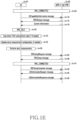
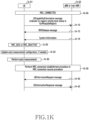
- FIG. 1H is a flowchart for a method of releasing an early measurement result value by a UE in the disclosure.
- a terminal (UE) 1h-01 may establish an RRC connection to a base station (gNB or (ng)-eNB) 1h-02 so as to be in an RRC connected mode (RRC_CONNECTED).
- the UE 1h-01 may transmit a UE capability information (UECapabilityInformation) message to the base station 1h-02. This may follow the aforementioned embodiments. Additionally, the UE capability information message may contain capability information on whether to discard an early measurement result value stored in VarMeasIdleReport when the base station indicates to release the same via an RRC connection release message.
- UECapabilityInformation UECapabilityInformation
- the base station 1h-02 may transmit an RRC connection release (RRCRelease) message to the UE 1h-01.
- RRC connection release message may include an indicator indicating to, when there is an early measurement result value stored in VarMeasIdleReport of the UE 1h-01, release the early measurement result value.
- the indicator is included in the RRC connection release message
- the UE 1h-01 may release the early measurement result value stored in VarMeasIdleReport.
- the UE 1h-01 may maintain the early measurement result value stored in VarMeasIdleReport.
- measIdleConfig is included in the RRC connection release message, the aforementioned operation may be performed first, and then measIdleConfig may be applied according to the embodiments described above.
- the aforementioned indicator and UE operation may be applied only to the RRC connection release message containing suspendConfig.
- the UE 1h-01 may receive system information.
- the UE 1h-01 may transition to an RRC inactive mode (RRC_INACTIVE) or an RRC idle mode (RRC_IDLLE) according to the embodiments described above.
- RRC_INACTIVE RRC inactive mode
- RRC_IDLLE RRC idle mode
- a cell selection or re-selection procedure may be performed based on the system information. This may follow the aforementioned embodiments.
- the UE 1h-01 may update an early measurement configuration if necessary. This may follow the aforementioned embodiments.
- the UE 1h-01 may perform early measurement. This may follow the aforementioned embodiments.
- the UE 1h-01 may perform an RRC connection setup procedure or an RRC connection resumption procedure with the base station 1h-02 so as to transition to the RRC connected mode. This may follow the aforementioned embodiments.
- the UE 1h-01 may add idleModeAvailable to an RRC connection setup completion message or an RRC resumption completion message, and transmit the message to the base station 1h-02. This may follow the aforementioned embodiments.
- the base station 1h-02 may transmit the RRC connection release message to the UE 1h-01 so as to enable the UE 1h-01 in the RRC connected mode to transition to the RRC idle mode or the RRC inactive mode. If the RRC connection release message includes an indicator indicating to, when there is an early measurement result value stored in VarMeasIdleReport, release the early measurement result value, the UE 1h-01 may discard VarMeasIdleReport.
- the UE 1h-01 having received the RRC connection release message transitions to the RRC idle mode or the RRC inactive mode.
- the UE 1h-01 in the RRC idle mode or the RRC inactive mode may transition to the RRC connected mode by performing an RRC connection setup procedure or an RRC connection resumption procedure with the base station 1h-02. This may follow the aforementioned embodiments.
- the UE 1h-01 may transmit an RRC connection setup completion message or an RRC resumption completion message to the base station 1h-02 without including idleModeAvailable.
- FIG. 1I is a flowchart for a method of releasing an early measurement result value by a UE in the disclosure.
- the UE 1i-01 may transmit a UE capability information (UECapabilityInformation) message to the base station 1i-02. This may follow the aforementioned embodiments. Additionally, the UE capability information message may include capability information on whether VarMeasIdleReport can be released according to whether timer T331 is running if there is an early measurement result value stored in VarMeasIdleReport during a 2-step resume procedure (e.g., even if the UE has transmitted, to the base station, RRCResumeRequest or RRCResumeRequest1 for an RRC connection resumption procedure, the base station, in response thereto, transmits RRCRelease including suspension configuration information to the UE so that the UE 1i-01 continues to be in an RRC inactive mode).
- UECapabilityInformation UECapabilityInformation
- the base station 1i-02 may transmit an RRC connection release message (RRCRelease) to the UE 1i-01 so as to enable the UE 1h-01 to transition to the RRC inactive mode.
- RRCRelease RRC connection release message
- the UE 1i-01 may receive system information.
- the UE 1i-01 may transition to the RRC inactive mode.
- the UE 1i-01 may update an early measurement configuration if necessary. This may follow the aforementioned embodiments.
- the UE 1i-01 may perform early measurement. This may follow the aforementioned embodiments.
- the UE 1i-01 may transmit an RRC connection resumption request message (RRCResumeRequest or RRCResumeRequest1) to the base station 1i-02 to initiate a 2-step resume procedure.
- the UE 1i-01 may set resumeCause with rna-Update and transmit the RRC connection resumption request message to the base station 1i-02.
- the UE 1j-01 may transmit a UE capability information (UECapabilityInformation) message to the base station 1j-02. This may follow the aforementioned embodiments. Additionally, the UE capability information message may include capability information on whether the UE 1j-01 releases VarMeasIdleReport when running timer T331 expires and/or when timer T331 is stopped. Alternatively, the UE capability information message may include capability information on whether the UE no longer performs early measurement based on system information when running timer T331 expires and/or when timer T331 is stopped.
- UECapabilityInformation UECapabilityInformation
- FIG. 1L is a flowchart for a method of releasing an early measurement result value by a UE in the disclosure.
- a terminal (UE) 11-01 may establish an RRC connection to a base station (gNB or (ng)-eNB) 1i-02 so as to be in an RRC connected mode (RRC_CONNECTED).
- the UE 11-01 may transmit a UE capability information message (UECapabilityInformation) to the base station 1i-02. This may follow the aforementioned embodiments. Additionally, the UE capability information message may contain capability information on whether VarMeasIdleReport can be released if an RRC connection release message does not include a measIdleDuration value.
- UECapabilityInformation UE capability information message
- the UE capability information message may contain capability information on whether VarMeasIdleReport can be released if an RRC connection release message does not include a measIdleDuration value.
- the base station 1i-02 may transmit an RRC connection release (RRCRelease) message to the UE 11-01. If the RRC connection release message includes no measIdleDuration value and includes VarMeasIdleReport, the UE 11-01 may release VarMeasIdleReport.
- RRC connection release RRCRelease
- the procedure described above may be applied to all cases or may be applied only to a 2-step resumption procedure. Alternatively, the procedure may be applied only when timer T331 expires or is stopped.
- FIG. 1M is a flowchart for a method of releasing an early measurement result value by a UE in the disclosure.
- a terminal (UE) 1m-01 may establish an RRC connection to a base station (gNB or (ng)-eNB) 1m-02 so as to be in an RRC connected mode (RRC_CONNECTED).
- the UE 1m-01 may transmit a UE capability information message (UECapabilityInformation) to the base station 1m-02. This may follow the aforementioned embodiments. Additionally, the UE capability information message may include capability information that new timer information is applicable, the new timer information indicating when to release VarMeasIdleReport of the UE 1m-01.
- UECapabilityInformation UECapabilityInformation
- the UE capability information message may include capability information that new timer information is applicable, the new timer information indicating when to release VarMeasIdleReport of the UE 1m-01.
- the base station 1m-02 may transmit an RRC connection release (RRCRelease) message to the UE 1m-01.
- the RRC connection release message may include a new timer value for when to release VarMeasIdleReport. That is, when a new timer expires, the UE 1m-01 may release VarMeasIdleReport.
- the UE 1m-01 may run the new timer with the new timer value when the RRC connection release message is received, or may run the new timer with the new timer value when timer T331 expires or when running timer T331 is stopped. If the new timer expires, the UE 1m-01 may release VarMeasIdleReport.
- the UE 1m-01 may not transmit a predetermined RRC message including idleMeasAvailable to the base station 1m-02.
- the UE 1m-01 may continue to run the new timer even when VarMeasIdleConfig is released.
- FIG. 1N is a flowchart for a method of releasing an early measurement result value by a UE in the disclosure.
- a terminal (UE) 1n-01 may establish an RRC connection to a base station (gNB or (ng)-eNB) 1n-02 so as to be in an RRC connected mode (RRC_CONNECTED).
- the UE 1n-01 may transmit a UE capability information (UECapabilityInformation) message to the base station 1n-02. This may follow the aforementioned embodiment. Additionally, the UE capability information message may include capability information that new timer information is applicable, the new timer information indicating when to release VarMeasIdleReport of the UE 1n-01.
- UECapabilityInformation UECapabilityInformation
- the UE capability information message may include capability information that new timer information is applicable, the new timer information indicating when to release VarMeasIdleReport of the UE 1n-01.
- the base station 1n-02 may transmit an RRC connection release message (RRCRelease) to the UE 1n-01.
- the RRC connection release message may include a new timer value for when to release VarMeasIdleReport.
- the new timer value may be included in another predetermined RRC message.
- the UE 1n-01 may perform an RRC connection setup procedure or an RRC connection resumption procedure with the base station 1n-02 so as to transition to the RRC connected mode. This may follow the aforementioned embodiments.
- the UE 1n-01 may add idleModeAvailable to an RRC connection setup completion message or an RRC resumption completion message, and transmit the message to the base station 1n-02. This may follow the aforementioned embodiments. In this case, additionally, the UE 1n-01 may run a new timer with the new timer value received from the base station 1n-02.
- the new timer may expire.
- the base station 1n-02 may transmit a UE information request (UEInformationRequest) message to the UE 1n-01 in order to retrieve a measurement result stored in VarMeasIdleReport of the UE 1n-01.
- UEInformationRequest UE information request
- This may follow the aforementioned embodiment.
- operation 1n-35 may not be performed.
- the UE 1n-01 may transmit, to the base station 1n-02, an indicator in a UE information response (UEInformationResponse) message, wherein the indicator is to indicate the release of VarMeasIdleReport.
- UEInformationResponse UE information response
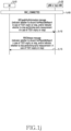
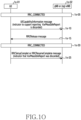
- FIG. 1O is a flowchart in which a UE transmits, to a base station, and indicator indicating that an early measurement result value has been released, in the disclosure.
- a terminal (UE) 1o-01 may establish an RRC connection to a base station (gNB or (ng)-eNB) 1o-02 so as to be in an RRC connected mode (RRC_CONNECTED).
- the UE 1o-01 may transmit a UE capability information (UECapabilityInformation) message to the base station 1o-02. This may follow the aforementioned embodiments. Additionally, the UE capability information message may include capability information including, in RRCResumeComplete or RRCSetupComplete, an indicator indicating that VarMeasIdleReport has been released.
- UECapabilityInformation UECapabilityInformation
- the UE capability information message may include capability information including, in RRCResumeComplete or RRCSetupComplete, an indicator indicating that VarMeasIdleReport has been released.
- the base station 1o-02 may transmit an RRC connection release message (RRCRelease) to the UE 1o-01.
- the UE 1o-01 may perform an RRC connection setup procedure or an RRC connection resumption procedure with the base station 1o-02 so as to transition to the RRC connected mode. This may follow the aforementioned embodiments.
- the UE 1o-01 may add an indicator indicating that VarMeasIdleReport has been released to an RRC connection setup completion message or an RRC resumption completion message.
- the base station 1o-02 adds idleModeMeasurementReq to the RRCResume message, but when the UE 1o-01 releases VarMeasIdleReport, the RRC connection resumption complete message may include an indicator indicating that VarMeasIdleReport has been released.
- the method of releasing VarMeasIdleReport by the UE 1o-01 may follow one of the embodiments described above.
- the UE 1o-01 may release VarMeasIdleReport and perform transmission to the base station 1o-02 while including the indicator indicating the release of VarMeasIdleReport.
- FIG. 1P is a block diagram illustrating an internal structure of a UE according to an embodiment of the disclosure.
- the UE may include a radio frequency (RF) processor 1p-10, a baseband processor 1p-20, a storage unit 1p-30, and a controller 1p-40.
- RF radio frequency
- the example given above is not limiting, and the UE may include more components than those illustrated in FIG. 1P or may include less components than those illustrated in FIG. 1P .
- the RF processor 1p-10 may perform a function for transmitting and receiving a signal via a wireless channel, such as band conversion and amplification of the signal. That is, the RF processor 1p-10 may up-convert a baseband signal provided from the baseband processor 1p-20 to an RF band signal, may transmit the same through an antenna, and may down-convert an RF band signal received through the antenna to a baseband signal.
- the RF processor 1p-10 may include a transmission filter, a reception filter, an amplifier, a mixer, an oscillator, a digital-to-analog converter (DAC), an analog-to-digital converter (ADC), and the like.
- DAC digital-to-analog converter
- ADC analog-to-digital converter
- the UE may include multiple antennas.
- the RF processor 1p-10 may include multiple RF chains.
- the RF processor 1p-10 may perform beamforming. For the beamforming, the RF processor 1p-10 may adjust the phase and magnitude of each of signals transmitted and received through multiple antennas or antenna elements.
- the RF processor 1p-10 may perform MIMO, and may receive multiple layers when performing MIMO operations.
- the baseband processor 1p-20 may perform functions of conversion between baseband signals and bitstrings according to the system's physical layer specifications. For example, during data transmission, the baseband processor 1p-20 may encode and modulate a transmitted bitstring to generate complex symbols. In addition, during data reception, the baseband processor 1p-20 may demodulate and decode a baseband signal provided from the RF processor 1p-10 to restore a received bitstring. For example, when following the orthogonal frequency division multiplexing (OFDM) scheme, during data transmission, the baseband processor 1p-20 may encode and modulate a transmitted bitstring to generate complex symbols, may map the complex symbols to subcarriers, and may configure OFDM symbols through an inverse fast Fourier transform (IFFT) operation and cyclic prefix (CP) insertion.
- OFDM orthogonal frequency division multiplexing
- the baseband processor 1p-20 may split a baseband signal provided from the RF processor 1i-10 at the OFDM symbol level, may restore signals mapped to subcarriers through a fast Fourier transform (FFT) operation, and may restore a received bitstring through demodulation and decoding.
- FFT fast Fourier transform
- the baseband processor 1p-20 and the RF processor 1p-10 may transmit and receive signals as described above. Accordingly, each of the baseband processor 1p-20 and the RF processor 1p-10 may be referred to as a transmitter, a receiver, a transceiver, or a communicator. Furthermore, at least one of the baseband processor 1p-20 and the RF processor 1p-10 may include multiple communication modules to support multiple different radio access technologies. In addition, at least one of the baseband processor 1p-20 and the RF processor 1p-10 may include different communication modules to process signals in different frequency bands. For example, the different radio access technologies may include a wireless LAN (e.g., IEEE 802.11), a cellular network (e.g., LTE), and the like.
- a wireless LAN e.g., IEEE 802.11
- a cellular network e.g., LTE
- the different frequency bands may include super high frequency (SHF) (e.g., 2 NRHz) bands and millimeter wave (mmWave) (e.g., 60GHz) bands.
- SHF super high frequency
- mmWave millimeter wave
- the UE may transmit/receive a signal with the base station by using the baseband processor 1p-20 and the RF processor 1p-10, and the signal may include control information and data.
- the storage unit 1p-30 may store data such as a basic program, an application, or configuration information for the operations of the UE.
- the storage unit 1p-30 may store data such as basic programs, application programs, and configuration information for the above-described operations of the UE.
- the storage unit 1p-30 may provide the stored data at the request of the controller 1p-40.
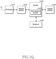
- FIG. 1Q is a block diagram illustrating a structure of an NR base station according to an embodiment of the disclosure.
- the base station may include an RF processor 1q-10, a baseband processor 1q-20, a backhaul communication unit 1q-30, a storage unit 1q-40, and a controller 1q-50.
- the base station may include more components than those illustrated in FIG. 1Q or may include less components than those illustrated in FIG. 1Q .
- the RF processor 1q-10 may perform a function for transmitting and receiving a signal via a wireless channel, such as band conversion and amplification of the signal. That is, the RF processor 1q-10 may up-convert a baseband signal provided from the baseband processor 1q-20 to an RF band signal, may transmit the same through an antenna, and may down-convert an RF band signal received through the antenna to a baseband signal.
- the RF processor 1q-10 may include a transmission filter, a reception filter, an amplifier, a mixer, an oscillator, a DAC, and an ADC. Although only one antenna is illustrated in FIG. 1Q , the RF processing unit 1q-10 may include multiple antennas.
- the RF processor 1q-10 may include multiple RF chains. Furthermore, the RF processor 1q-10 may perform beamforming. For the beamforming, the RF processor 1q-10 may adjust the phase and magnitude of each of signals transmitted and received through multiple antennas or antenna elements. The RF processing unit 1q-10 may transmit one or more layers to perform a downward MIMO operation.
Landscapes
- Engineering & Computer Science (AREA)
- Signal Processing (AREA)
- Computer Networks & Wireless Communication (AREA)
- Computer Security & Cryptography (AREA)
- Databases & Information Systems (AREA)
- Mobile Radio Communication Systems (AREA)
Applications Claiming Priority (2)
| Application Number | Priority Date | Filing Date | Title |
|---|---|---|---|
| KR1020220128119A KR20240048392A (ko) | 2022-10-06 | 2022-10-06 | 이동통신 시스템에서 early measurement 수행 방법 및 장치 |
| PCT/KR2023/015358 WO2024076181A1 (ko) | 2022-10-06 | 2023-10-05 | 이동통신 시스템에서 early measurement 수행 방법 및 장치 |
Publications (2)
| Publication Number | Publication Date |
|---|---|
| EP4580246A1 true EP4580246A1 (de) | 2025-07-02 |
| EP4580246A4 EP4580246A4 (de) | 2026-01-21 |
Family
ID=90608380
Family Applications (1)
| Application Number | Title | Priority Date | Filing Date |
|---|---|---|---|
| EP23875243.0A Pending EP4580246A4 (de) | 2022-10-06 | 2023-10-05 | Verfahren und vorrichtung zur durchführung einer frühen messung in einem mobilkommunikationssystem |
Country Status (3)
| Country | Link |
|---|---|
| EP (1) | EP4580246A4 (de) |
| KR (1) | KR20240048392A (de) |
| WO (1) | WO2024076181A1 (de) |
Family Cites Families (4)
| Publication number | Priority date | Publication date | Assignee | Title |
|---|---|---|---|---|
| KR102854552B1 (ko) * | 2019-02-13 | 2025-09-02 | 삼성전자주식회사 | 무선 통신 시스템에서 캐리어 어그리게이션을 지원하기 위한 방법 및 장치 |
| US12144054B2 (en) * | 2019-06-25 | 2024-11-12 | Telefonaktiebolaget Lm Ericsson (Publ) | Handling of idle measurement results in RRC_connected |
| WO2020263152A1 (en) * | 2019-06-28 | 2020-12-30 | Telefonaktiebolaget Lm Ericsson (Publ) | Early measurement reporting to second node |
| US11438784B2 (en) * | 2020-01-24 | 2022-09-06 | Telefonaktiebolaget Lm Ericsson (Publ) | Methods supporting early measurement information in logged minimization of drive tests (MDT) measurement reports and related communication devices and network nodes |
-
2022
- 2022-10-06 KR KR1020220128119A patent/KR20240048392A/ko active Pending
-
2023
- 2023-10-05 EP EP23875243.0A patent/EP4580246A4/de active Pending
- 2023-10-05 WO PCT/KR2023/015358 patent/WO2024076181A1/ko not_active Ceased
Also Published As
| Publication number | Publication date |
|---|---|
| EP4580246A4 (de) | 2026-01-21 |
| KR20240048392A (ko) | 2024-04-15 |
| WO2024076181A1 (ko) | 2024-04-11 |
Similar Documents
| Publication | Publication Date | Title |
|---|---|---|
| US20240188176A1 (en) | Method and apparatus by which user equipment manages short-time switching gap configuration information in mobile communication system | |
| US20240188174A1 (en) | Method and device for managing long-time switching timer in wireless communication system | |
| US20230124607A1 (en) | Apparatus and method for conditional mobility on secondary node initiated by master node in wireless communication systems | |
| US12520121B2 (en) | Method and apparatus in which UE supporting multiple USIMS transmits UE assistance information in wireless communication system | |
| EP4622328A1 (de) | Verfahren und vorrichtung zur aktualisierung der flugbahn in einem mobilkommunikationssystem der nächsten generation | |
| US20240056935A1 (en) | Method and device for performing conditional handover in wireless communication system | |
| US20240224100A1 (en) | Method and apparatus for configuring and reporting qoe in wireless communication system | |
| US20240155445A1 (en) | Method of configuring handover using physical layer and mac layer signaling in next generation mobile communication system | |
| US20240121770A1 (en) | Method and device for scheduling in wireless communication system | |
| US20250024356A1 (en) | Method and device for providing capability restriction information of musim terminal in next-generation mobile communication system | |
| US20250105958A1 (en) | Method and device for multi-sim ue to manage colliding gaps in next generation mobile communication system | |
| US20240389184A1 (en) | Method and apparatus for transmitting segmented rrc message in wireless communication system | |
| EP4525494A1 (de) | Verfahren und vorrichtung zur verwaltung der lückenpriorität für ein musim-endgerät in einem drahtloskommunikationssystem | |
| EP4593465A1 (de) | Verfahren und vorrichtung zur durchführung einer übergabe von gruppenendgeräten zur reduzierung des netzwerkenergieverbrauchs in einem drahtloskommunikationssystem | |
| US20240007371A1 (en) | Method and apparatus for controlling beam failure detection in wireless communication system | |
| EP4557696A1 (de) | Verfahren und vorrichtung zur verwerfung von pdcp-sdu in einem drahtloskommunikationssystem | |
| US20240154880A1 (en) | Method and apparatus for qoe measurement of ue in dual connectivity in a wireless communication system | |
| US20240107387A1 (en) | Method and apparatus for measurement reporting of uncrewed aerial vehicle terminal in non-terrestrial network | |
| US20240049076A1 (en) | Method and apparatus for performing conditional pscell addition and change continuously in wireless communication system | |
| US20230262549A1 (en) | Method and apparatus for ue capability signaling for conditional pscell change in wireless communication system | |
| US20230262825A1 (en) | Method and apparatus for the conditional pscell change in next generation mobile communication system | |
| US20250324240A1 (en) | Method and apparatus for reporting ue capability in next generation wireless communication system | |
| US20240373492A1 (en) | Method and apparatus for applying configuration of child node for migration in backhaul-access hole combined system | |
| EP4580246A1 (de) | Verfahren und vorrichtung zur durchführung einer frühen messung in einem mobilkommunikationssystem | |
| US20250234410A1 (en) | Method and apparatus for configuring ip address to integrated access and backhaul node in wireless communication system |
Legal Events
| Date | Code | Title | Description |
|---|---|---|---|
| STAA | Information on the status of an ep patent application or granted ep patent |
Free format text: STATUS: THE INTERNATIONAL PUBLICATION HAS BEEN MADE |
|
| PUAI | Public reference made under article 153(3) epc to a published international application that has entered the european phase |
Free format text: ORIGINAL CODE: 0009012 |
|
| STAA | Information on the status of an ep patent application or granted ep patent |
Free format text: STATUS: REQUEST FOR EXAMINATION WAS MADE |
|
| 17P | Request for examination filed |
Effective date: 20250327 |
|
| AK | Designated contracting states |
Kind code of ref document: A1 Designated state(s): AL AT BE BG CH CY CZ DE DK EE ES FI FR GB GR HR HU IE IS IT LI LT LU LV MC ME MK MT NL NO PL PT RO RS SE SI SK SM TR |
|
| DAV | Request for validation of the european patent (deleted) | ||
| DAX | Request for extension of the european patent (deleted) | ||
| A4 | Supplementary search report drawn up and despatched |
Effective date: 20251222 |
|
| RIC1 | Information provided on ipc code assigned before grant |
Ipc: H04W 24/10 20090101AFI20251217BHEP Ipc: H04W 76/27 20180101ALI20251217BHEP Ipc: H04W 76/25 20180101ALI20251217BHEP Ipc: H04W 48/08 20090101ALI20251217BHEP Ipc: H04W 48/18 20090101ALI20251217BHEP Ipc: H04W 76/30 20180101ALN20251217BHEP Ipc: H04W 8/24 20090101ALN20251217BHEP Ipc: H04L 5/00 20060101ALN20251217BHEP |