EP4580237A1 - Basisstationsvorrichtung, kommunikationssystem, strahlsuchverfahren und programm - Google Patents
Basisstationsvorrichtung, kommunikationssystem, strahlsuchverfahren und programm Download PDFInfo
- Publication number
- EP4580237A1 EP4580237A1 EP22956542.9A EP22956542A EP4580237A1 EP 4580237 A1 EP4580237 A1 EP 4580237A1 EP 22956542 A EP22956542 A EP 22956542A EP 4580237 A1 EP4580237 A1 EP 4580237A1
- Authority
- EP
- European Patent Office
- Prior art keywords
- candidate
- pilot signal
- same
- base station
- beams
- Prior art date
- Legal status (The legal status is an assumption and is not a legal conclusion. Google has not performed a legal analysis and makes no representation as to the accuracy of the status listed.)
- Pending
Links
Images


Classifications
-
- H—ELECTRICITY
- H04—ELECTRIC COMMUNICATION TECHNIQUE
- H04W—WIRELESS COMMUNICATION NETWORKS
- H04W16/00—Network planning, e.g. coverage or traffic planning tools; Network deployment, e.g. resource partitioning or cells structures
- H04W16/24—Cell structures
- H04W16/28—Cell structures using beam steering
-
- H—ELECTRICITY
- H04—ELECTRIC COMMUNICATION TECHNIQUE
- H04L—TRANSMISSION OF DIGITAL INFORMATION, e.g. TELEGRAPHIC COMMUNICATION
- H04L5/00—Arrangements affording multiple use of the transmission path
- H04L5/003—Arrangements for allocating sub-channels of the transmission path
- H04L5/0048—Allocation of pilot signals, i.e. of signals known to the receiver
-
- H—ELECTRICITY
- H04—ELECTRIC COMMUNICATION TECHNIQUE
- H04B—TRANSMISSION
- H04B7/00—Radio transmission systems, i.e. using radiation field
- H04B7/02—Diversity systems; Multi-antenna system, i.e. transmission or reception using multiple antennas
- H04B7/04—Diversity systems; Multi-antenna system, i.e. transmission or reception using multiple antennas using two or more spaced independent antennas
- H04B7/06—Diversity systems; Multi-antenna system, i.e. transmission or reception using multiple antennas using two or more spaced independent antennas at the transmitting station
- H04B7/0686—Hybrid systems, i.e. switching and simultaneous transmission
- H04B7/0695—Hybrid systems, i.e. switching and simultaneous transmission using beam selection
- H04B7/06952—Selecting one or more beams from a plurality of beams, e.g. beam training, management or sweeping
Definitions
- Methods of selecting the candidate beams have also been defined and installed in wireless communication systems put into practical use in recent years, such as 3GPP (registered trademark) 5th generation (5G) or IEEE802.11ad/ay (for example, see Non-Patent Documents 1, 2, and 3). In this way, beams to be used for communication are searched for.
- 3GPP registered trademark
- 5G 5th generation
- IEEE802.11ad/ay for example, see Non-Patent Documents 1, 2, and 3
- a beam searching method includes: a candidate beam determination step of determining candidate beams that are candidates for a beam of a pilot signal to be transmitted for each terminal device that is a transmission partner; a beam ID assignment step of assigning a different beam ID to the candidate beam of the same terminal device and assigning beam IDs to candidate beams among different terminal devices so that the number of combinations of the candidate beams to which the same beam ID is assigned is maximized; and a pilot signal generation step of generating a pilot signal to be transmitted in a same time domain and a same frequency domain for each candidate beam to which the same beam ID is assigned.
- the base station device According to the base station device, the communication system, and the beam searching method of the present invention, it is possible to inhibit an increase in time and frequency resources in beam searching.
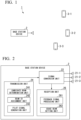
- the candidate beam determination unit 241 determines candidate beams that are candidates for a beam of a pilot signal to be transmitted for each terminal device 3. For example, of the wide beams searched for using a wide beam with a large width, a beam with a finer range than the wide beam with the best reception sensitivity for each terminal device 3 is determined as the candidate beam of that terminal device 3. For example, the periphery of the beam used when the base station device 2 transmits a signal for each terminal device 3 is determined as the candidate beam of this terminal device 3.
- the former method is performed, for example, when the base station device 2 and the terminal device 3 have not performed communication previously.
- the latter method is performed, for example, when the base station device 2 and the terminal device 3 have already performed communication.
- the feedback signal is received by the antenna 21 of the base station device 2 and is converted into the digital signal by the signal conversion unit 22.
- the feedback signal processing unit 261 processes the feedback signal and acquires the information regarding the candidate beam to be used.
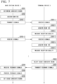
- FIG. 7 is a sequence diagram illustrating an operation of the communication system 1.
- the candidate beam determination unit 241 of the base station device 2 determines the candidate beams for each terminal device 3 (step S201).
- the beam ID assignment unit 242 assigns the beam IDs to the candidate beams (step S202).
- the beam ID assignment unit 242 assigns the different beam IDs to the candidate beams of the same terminal device 3 and assigns the beam IDs to the candidate beams among the different terminal devices 3 so that the number of combinations of the candidate beams to which the same beam ID is assigned is maximized.
- the beam ID assignment unit 242 may assign the same beam ID.
- the pilot signal generation unit 243 generates the pilot signals
- the signal conversion unit 22 converts the pilot signals to the analog signals
- the converted analog signals are transmitted from the antenna 21 to the terminal device 3 (step S203).
- a transmission order of the pilot signals is based on the beam IDs. For example, the antenna 21 first transmits the pilot signal with the candidate beam of which the beam ID is #1 (step S203-1), subsequently transmits the pilot signal with the candidate beam of which the beam ID is #2 (step S203-2), and the pilot signals are continuously transmitted with all the candidate beams.
- the terminal device 3 receives the pilot signals using the antenna 31 (step S301) and the signal conversion unit 32 converts the pilot signals from the analog signals to the digital signals.
- the signal processing unit 341 processes the pilot signals and acquires the information regarding the beam IDs (step S302).
- the reception unit 34 acquires the timings at which the candidate beams are transmitted by acquiring the timings at which the transmission of the signals starts and the time intervals at which the candidate beams are switched, and estimates the beam IDs corresponding to the unmodulated wave signals.
- the reception quality measurement unit 342 measures the reception quality of the received signals (step S303).
- the terminal devices 3 perform operations of steps S301 to S303 whenever the pilot signals are received.
- the terminal device 3-1 performs operations of steps S301-1 to S303-1 when the pilot signals transmitted with the candidate beams of which the beam IDs are #1 are received, performs operations of steps S301-2 to S303-2 when the pilot signals transmitted with the candidate beams of which the beam IDs are #2 are received, and performs operations on all the following pilot signals.
- the other terminal devices 3 measure reception quality of all the transmitted pilot signals by performing the same operations.
- the usage candidate beam selection unit 343 selects the candidate beams to be used based on the reception quality (step S304). Thereafter, the feedback signal generation unit 36 generates the feedback signals including the information regarding the candidate beams to be used and the signal conversion unit 32 converts the feedback signals into analog signals, and the converted analog signals are transmitted from the antenna 31 (step S305).
- the antenna 21 of the base station device 2 receives the feedback signals (step S204), the signal conversion unit converts the feedback signals from the analog signals to the digital signals, the feedback signal processing unit 261 processes the feedback signals to acquire the information regarding usage candidate beams (step S205).
- the usage beam setting unit 262 sets the beams to be used based on the information regarding the usage candidate beams in each terminal device 3 (step S206).
- the base station device 2 can assign the same beam ID to the duplicated candidate beam and transmit the pilot signal as one candidate beam.
- the pilot signals are not transmitted with two candidate beams for each terminal device 3 and one pilot signal is transmitted based on two candidate beams. Accordingly, it is possible to save the resources with which one pilot signal is transmitted from time T 1 to time T 2 and it is possible to save resources with which one pilot signal is transmitted from time T 2 to time T 3 .
- the communication system 1 according to the present embodiment can save resources with which the signals are transmitted when the base station device 2 selects the beams to be used for communication.
- the terminal device 3 determines a candidate beam for each base station device 2, assigns a beam ID to the candidate beam for the base station device 2, and generates a pilot signal, and thus it is possible to inhibit an increase in time and frequency resources.
- the pilot signal can be replaced with a reference signal, a control signal, control information, or a control channel.
- the beam ID can also be notified of not only with the pilot signal but also the reference signal, the control signal, the control information, or the control channel.
- the beam ID may be information regarding a beam.
- the terminal device 3 may be notified of the beam ID by using resource IDs of reference signals generated based on the candidate beams to which the same beam ID is assigned.
- the transmission unit 24 includes the candidate beam determination unit 241, the beam ID assignment unit 242, and the pilot signal generation unit 243.
- the reception unit 26 includes the feedback signal processing unit 261 and the usage beam setting unit 262.
- the reception unit 34 includes the signal processing unit 341, the reception quality measurement unit 342, and the usage candidate beam selection unit 343.
- These constituent elements and the feedback signal generation unit 36 are realized, for example, by causing a hardware processor such as a central processing unit (CPU) to execute a program (software).
- Some or all of the constituent elements may be realized by hardware (including circuitry) such as a large scale integration (LSI), an application specific integrated circuit (ASIC), a field-programmable gate array (FPGA), or a graphics processing unit (GPU) or may be realized by software and hardware in combination.
- LSI large scale integration
- ASIC application specific integrated circuit
- FPGA field-programmable gate array
- GPU graphics processing unit
- the program may be stored in advance in a storage device (a storage device including a non-transitory storage medium) such as a hard disk drive (HDD) or a flash memory or may be stored in a detachable storage medium such as a DVD or a CD-ROM (non-transitory storage medium) and installed when the storage medium is mounted on a drive device.
- a storage device a storage device including a non-transitory storage medium
- a storage device including a non-transitory storage medium
- HDD hard disk drive
- flash memory or may be stored in a detachable storage medium such as a DVD or a CD-ROM (non-transitory storage medium) and installed when the storage medium is mounted on a drive device.
Landscapes
- Engineering & Computer Science (AREA)
- Signal Processing (AREA)
- Computer Networks & Wireless Communication (AREA)
- Mobile Radio Communication Systems (AREA)
Applications Claiming Priority (1)
| Application Number | Priority Date | Filing Date | Title |
|---|---|---|---|
| PCT/JP2022/032247 WO2024042716A1 (ja) | 2022-08-26 | 2022-08-26 | 基地局装置、通信システム、ビーム探索方法及びプログラム |
Publications (1)
| Publication Number | Publication Date |
|---|---|
| EP4580237A1 true EP4580237A1 (de) | 2025-07-02 |
Family
ID=90012858
Family Applications (1)
| Application Number | Title | Priority Date | Filing Date |
|---|---|---|---|
| EP22956542.9A Pending EP4580237A1 (de) | 2022-08-26 | 2022-08-26 | Basisstationsvorrichtung, kommunikationssystem, strahlsuchverfahren und programm |
Country Status (3)
| Country | Link |
|---|---|
| EP (1) | EP4580237A1 (de) |
| JP (1) | JP7807556B2 (de) |
| WO (1) | WO2024042716A1 (de) |
Family Cites Families (4)
| Publication number | Priority date | Publication date | Assignee | Title |
|---|---|---|---|---|
| JP2017200004A (ja) * | 2016-04-26 | 2017-11-02 | 富士通株式会社 | 無線通信装置及びビーム探索方法 |
| JP6984189B2 (ja) * | 2017-06-14 | 2021-12-17 | ソニーグループ株式会社 | 基地局装置、基地局装置の制御方法、端末装置及び端末装置の制御方法 |
| CN109586771A (zh) * | 2017-09-29 | 2019-04-05 | 索尼公司 | 电子设备和通信方法 |
| EP3598657B1 (de) * | 2018-07-19 | 2021-06-09 | Mitsubishi Electric R & D Centre Europe B.V. | Verfahren zur konfiguration eines mu-mimo-drahtlossenders |
-
2022
- 2022-08-26 WO PCT/JP2022/032247 patent/WO2024042716A1/ja not_active Ceased
- 2022-08-26 EP EP22956542.9A patent/EP4580237A1/de active Pending
- 2022-08-26 JP JP2024542561A patent/JP7807556B2/ja active Active
Also Published As
| Publication number | Publication date |
|---|---|
| JP7807556B2 (ja) | 2026-01-27 |
| WO2024042716A1 (ja) | 2024-02-29 |
| JPWO2024042716A1 (de) | 2024-02-29 |
Similar Documents
| Publication | Publication Date | Title |
|---|---|---|
| JP6419817B2 (ja) | それぞれ同期信号および関連情報を送信し、検出するためのネットワークノード、ワイヤレスデバイス、およびそれらにおける方法 | |
| EP3017557B1 (de) | Verfahren und vorrichtung für resonanzkanalbetrieb in millimeterwellen-kommunikationssystemen | |
| US12395872B2 (en) | Radio communication method, radio communication system, radio base station, and reflector | |
| US20190296804A1 (en) | Double one-dimensional sector sweep scan | |
| US20140139372A1 (en) | Beam direction selection method and apparatus for use in beamforming system | |
| KR20180040368A (ko) | 무선 통신 시스템에서 안테나 구성에 기반한 빔 탐색 장치 및 방법 | |
| WO2020237534A1 (en) | Methods, devices and computer storage media for communication | |
| CN117015937A (zh) | 参考信号资源的传输 | |
| KR102246608B1 (ko) | 무선 통신 시스템에서 송신 전력을 제어하기 위한 장치 및 방법 | |
| CN118018953A (zh) | 无线感知方法、信息反馈方法、装置、存储介质和设备 | |
| US20260046182A1 (en) | Method of adaptive transmission beam sweeping, method of controlling adaptive transmission beam sweeping, user equipment, base station and computer readable media | |
| US11218239B2 (en) | Operating method of terminal in wireless communication system and terminal for performing the method | |
| KR20230014554A (ko) | Irs 서비스 영역 탐지 장치 및 방법 | |
| US12603806B2 (en) | Communication control apparatus, communication system, and method | |
| CN119631345A (zh) | 用于干扰随机化的srs增强 | |
| WO2017076311A1 (en) | System and method for large scale multiple input multiple output beamforming | |
| KR20240021002A (ko) | 무선 통신 시스템에서 ris 제어를 위한 빔 북을 획득하는 방법 및 장치 | |
| US20240333344A1 (en) | Communication control method and communication control apparatus | |
| EP4580237A1 (de) | Basisstationsvorrichtung, kommunikationssystem, strahlsuchverfahren und programm | |
| WO2020101756A2 (en) | Method and apparatus of antenna array group selection and antenna array selection for device communications | |
| EP4583423A1 (de) | Betriebsverfahren für benutzergerät zur strahlformung in einem drahtloskommunikationssystem und benutzergerät dafür | |
| US11509378B2 (en) | Apparatus search for optimal directional beams | |
| WO2024174246A1 (en) | Devices, methods, and apparatuses for joint communication and sensing | |
| CN113938168B (zh) | 上下行非对称通信mimo系统的劈裂波束管理方法及系统 | |
| JP2020155894A (ja) | ユーザ装置及び基地局装置 |
Legal Events
| Date | Code | Title | Description |
|---|---|---|---|
| STAA | Information on the status of an ep patent application or granted ep patent |
Free format text: STATUS: THE INTERNATIONAL PUBLICATION HAS BEEN MADE |
|
| PUAI | Public reference made under article 153(3) epc to a published international application that has entered the european phase |
Free format text: ORIGINAL CODE: 0009012 |
|
| STAA | Information on the status of an ep patent application or granted ep patent |
Free format text: STATUS: REQUEST FOR EXAMINATION WAS MADE |
|
| 17P | Request for examination filed |
Effective date: 20250221 |
|
| AK | Designated contracting states |
Kind code of ref document: A1 Designated state(s): AL AT BE BG CH CY CZ DE DK EE ES FI FR GB GR HR HU IE IS IT LI LT LU LV MC MK MT NL NO PL PT RO RS SE SI SK SM TR |
|
| RAP3 | Party data changed (applicant data changed or rights of an application transferred) |
Owner name: NTT, INC. Owner name: NTT DOCOMO, INC. |
|
| DAV | Request for validation of the european patent (deleted) | ||
| DAX | Request for extension of the european patent (deleted) |