EP4580205A1 - Elektronische vorrichtung, steuerungsverfahren für elektronische vorrichtung, programm und computerlesbares medium - Google Patents
Elektronische vorrichtung, steuerungsverfahren für elektronische vorrichtung, programm und computerlesbares medium Download PDFInfo
- Publication number
- EP4580205A1 EP4580205A1 EP24222810.4A EP24222810A EP4580205A1 EP 4580205 A1 EP4580205 A1 EP 4580205A1 EP 24222810 A EP24222810 A EP 24222810A EP 4580205 A1 EP4580205 A1 EP 4580205A1
- Authority
- EP
- European Patent Office
- Prior art keywords
- orientation
- imaging
- grip part
- electronic device
- display
- Prior art date
- Legal status (The legal status is an assumption and is not a legal conclusion. Google has not performed a legal analysis and makes no representation as to the accuracy of the status listed.)
- Pending
Links
Images




Classifications
-
- H—ELECTRICITY
- H04—ELECTRIC COMMUNICATION TECHNIQUE
- H04N—PICTORIAL COMMUNICATION, e.g. TELEVISION
- H04N23/00—Cameras or camera modules comprising electronic image sensors; Control thereof
- H04N23/60—Control of cameras or camera modules
- H04N23/695—Control of camera direction for changing a field of view, e.g. pan, tilt or based on tracking of objects
-
- H—ELECTRICITY
- H04—ELECTRIC COMMUNICATION TECHNIQUE
- H04N—PICTORIAL COMMUNICATION, e.g. TELEVISION
- H04N23/00—Cameras or camera modules comprising electronic image sensors; Control thereof
- H04N23/60—Control of cameras or camera modules
- H04N23/63—Control of cameras or camera modules by using electronic viewfinders
- H04N23/631—Graphical user interfaces [GUI] specially adapted for controlling image capture or setting capture parameters
- H04N23/632—Graphical user interfaces [GUI] specially adapted for controlling image capture or setting capture parameters for displaying or modifying preview images prior to image capturing, e.g. variety of image resolutions or capturing parameters
-
- H—ELECTRICITY
- H04—ELECTRIC COMMUNICATION TECHNIQUE
- H04N—PICTORIAL COMMUNICATION, e.g. TELEVISION
- H04N23/00—Cameras or camera modules comprising electronic image sensors; Control thereof
- H04N23/60—Control of cameras or camera modules
- H04N23/63—Control of cameras or camera modules by using electronic viewfinders
- H04N23/633—Control of cameras or camera modules by using electronic viewfinders for displaying additional information relating to control or operation of the camera
- H04N23/635—Region indicators; Field of view indicators
-
- H—ELECTRICITY
- H04—ELECTRIC COMMUNICATION TECHNIQUE
- H04N—PICTORIAL COMMUNICATION, e.g. TELEVISION
- H04N23/00—Cameras or camera modules comprising electronic image sensors; Control thereof
- H04N23/60—Control of cameras or camera modules
- H04N23/667—Camera operation mode switching, e.g. between still and video, sport and normal or high- and low-resolution modes
-
- H—ELECTRICITY
- H04—ELECTRIC COMMUNICATION TECHNIQUE
- H04N—PICTORIAL COMMUNICATION, e.g. TELEVISION
- H04N23/00—Cameras or camera modules comprising electronic image sensors; Control thereof
- H04N23/60—Control of cameras or camera modules
- H04N23/68—Control of cameras or camera modules for stable pick-up of the scene, e.g. compensating for camera body vibrations
- H04N23/681—Motion detection
- H04N23/6812—Motion detection based on additional sensors, e.g. acceleration sensors
-
- H—ELECTRICITY
- H04—ELECTRIC COMMUNICATION TECHNIQUE
- H04N—PICTORIAL COMMUNICATION, e.g. TELEVISION
- H04N23/00—Cameras or camera modules comprising electronic image sensors; Control thereof
- H04N23/60—Control of cameras or camera modules
- H04N23/68—Control of cameras or camera modules for stable pick-up of the scene, e.g. compensating for camera body vibrations
- H04N23/682—Vibration or motion blur correction
- H04N23/685—Vibration or motion blur correction performed by mechanical compensation
- H04N23/687—Vibration or motion blur correction performed by mechanical compensation by shifting the lens or sensor position
Definitions
- Japanese Patent Application Laid-Open No. 2015-180917 discloses a technique of separating a movement of an imaging apparatus into a movement of a low frequency component and a movement of a high frequency component, and canceling each of the movements in an appropriate form.
- the movement of the low frequency component is gently suppressed when a non-panning state transitions to a panning state.
- the present invention in its first aspect provides an electronic device as specified in claims 1 to 16.
- the present invention in its second aspect provides a control method as specified in claim 17.
- the present invention in its third aspect provides a program as specified in claim 18.
- the present invention in its fourth aspect provides a computer readable medium as specified in claim 19.
- FIGS. 1A and 1B are external views of a digital camera 100 (imaging apparatus) as an example of an apparatus (electronic device) to which the present invention can be applied.
- FIG. 1A is a front perspective view of the digital camera 100
- FIG. 1B is a rear perspective view of the digital camera 100.
- the digital camera 100 includes a grip part 90, an imaging unit 110, and an orientation control unit 300.
- the imaging unit 110 (imaging part) is disposed so as to be able to change its orientation with respect to the grip part 90.
- the orientation control unit 300 includes a pan shaft drive unit 301, a roll shaft drive unit 302, and a tilt shaft drive unit 303.
- the pan shaft drive unit 301 is fixed to the grip part 90, and the tilt shaft drive unit 303 is fixed to the imaging unit 110.
- the grip part 90 and the orientation control unit 300 may be separable, or the imaging unit 110 and the orientation control unit 300 may be separable.
- the imaging unit 110 may be a smartphone or the like.
- the orientation control unit 300 is a unit like an electric gimbal device, but a non-electric gimbal device may be used instead of the orientation control unit 300.
- a display unit 28 displays images and various types of information.
- a touch panel 70a can detect a touch operation on a display surface (touch operation surface) of the display unit 28.
- a shutter button 61 is an operation member for giving a shooting instruction.
- a mode selector switch 60 is an operation member for switching among various modes.
- a power switch 72 is an operation member for switching between ON and OFF of power supply of the digital camera 100.
- a controller wheel 73 is a rotatable operation member, and is used, for example, to instruct a selection item.
- an electrical pulse signal is generated according to an operation amount (rotation amount), and each unit of the digital camera 100 is controlled on the basis of the pulse signal.
- An angle and a rotation speed of the rotation operation for the controller wheel 73 can be determined by the pulse signal.
- the controller wheel 73 only needs to be an operation member capable of detecting a rotation operation, and may be, for example, a dial operation member in which the controller wheel 73 itself rotates according to the rotation operation to generate a pulse signal.
- the controller wheel 73 may be an operation member (so-called touch wheel) including a touch sensor, or may be an operation member that detects a rotational motion of a user's finger on the controller wheel 73 without rotation of the controller wheel 73 itself.
- a four-direction key 74 is configured to be able to press each of an upper portion, a lower portion, a left portion, and a right portion, and can perform processing corresponding to a pressed portion of the four-direction key 74.
- a SET button 75 is a push button, and is mainly used to determine a selection item.
- a movie button 76 is a push button, and is used for an instruction to start or stop movie shooting (recording).
- a menu button 81 is a push button used to perform an instruction operation for displaying a menu screen, and when the menu button 81 is pressed, a menu screen on which various settings can be made is displayed on the display unit 28. A user can perform various settings instinctively by using the menu screen displayed on the display unit 28, the four-direction key 74, and the SET button 75.
- FIG. 2 is a block diagram illustrating a configuration of the digital camera 100.
- An imaging lens 103 is a lens group including a zoom lens and a focus lens.
- a shutter 101 is a shutter having an aperture function.
- An imaging processing unit 22 is an imaging element (image sensor) constituted by a CCD, a CMOS element, or the like that converts an optical image into an electrical signal.
- An A/D converter 23 converts an analog signal output from the imaging processing unit 22 into a digital signal.
- a barrier 102 covers an imaging system including the imaging lens 103, the shutter 101, and the imaging processing unit 22 of the digital camera 100, thereby preventing contamination or damage of the imaging system.
- An image processing unit 24 performs predetermined processing (such as pixel interpolation, resizing processing such as shrinking, and color conversion processing) on data from the A/D converter 23 or data from a memory control unit 15.
- the image processing unit 24 performs predetermined arithmetic processing by using captured image data, and a system control unit 50 performs exposure control and distance measurement control on the basis of a result of the calculation obtained by the image processing unit 24.
- TTL through-the-lens
- AF through-the-lens
- AE auto exposure
- EF flash pre-flash
- the image processing unit 24 performs predetermined arithmetic processing by using the captured image data, and performs TTL-type auto white balance (AWB) processing on the basis of an obtained result of the calculation.
- the memory control unit 15 controls transmission and reception of data among the A/D converter 23, the image processing unit 24, and the memory 32. Output data from the A/D converter 23 is written into a memory 32 via the image processing unit 24 and the memory control unit 15. Alternatively, the output data from the A/D converter 23 is written into the memory 32 via the memory control unit 15 without intervention of the image processing unit 24.
- the memory 32 stores image data that is obtained by the imaging processing unit 22 and is converted into digital data by the A/D converter 23 and image data to be displayed on the display unit 28.
- the memory 32 has a storage capacity that is large enough to store a predetermined number of still images and movie images and voice in a predetermined time.
- the memory 32 also serves as a memory (video memory) for image display.
- the D/A converter 13 converts image data that is to be displayed and is stored in the memory 32 into an analog signal and supplies the analog signal to the display unit 28. Thus, the image data that is to be displayed and is written into the memory 32 is displayed by the display unit 28 via the D/A converter 13.
- a system memory 52 is, for example, a RAM, and the system control unit 50 loads constants, variables, and programs read from the nonvolatile memory 56 for an operation of the system control unit 50 into the system memory 52.
- the system control unit 50 also performs display control by controlling the memory 32, the D/A converter 13, the display unit 28, and the like.
- the system control unit 50 predicts an imaging range or a position of the imaging range at the time of completion of following by the imaging unit 110, and makes the imaging range or the position of the imaging range identifiable on the LV image.
- the user can easily grasp the direction in which the imaging unit 110 finally settles from the prediction range or the prediction position, and can adjust the direction of the grip part 90 before the imaging unit 110 settles.
- the user can easily direct the imaging unit 110 to his/her intended direction.
- the prediction range is a range predicted as an imaging range at the time of completion of following by the imaging unit 110
- the prediction position is a position predicted as a position of the imaging range at the time of completion of following by the imaging unit 110.
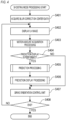
- the system control unit 50 performs motion amount acquisition processing of acquiring a motion amount (change amount of the orientation of the imaging unit 110) to be instructed to the orientation control unit 300.
- the system control unit 50 stores information of the acquired motion amount in the memory 32 via the memory control unit 15. Details of the motion amount acquisition processing will be described later with reference to FIG. 5 .
- the system control unit 50 acquires a prediction display mode and threshold setting information from the nonvolatile memory 56, and acquires the information of the motion amount of the orientation control unit 300 (information stored in the memory 32 in S403) from the memory 32 via the memory control unit 15. In a case where a mode of not performing the prediction display is set, the system control unit 50 determines not to perform the prediction display. In a case where a mode for displaying a frame indicating a prediction range, a mode for displaying a frame indicating the prediction range and a grid line of the frame, or a mode for displaying a point indicating a prediction position is set, the system control unit 50 determines whether or not the motion amount of the orientation control unit 300 is equal to or more than a threshold.
- the system control unit 50 performs prediction processing of predicting an imaging range or a position of the imaging range at the time of completion of following by the imaging unit 110. Details of the prediction processing will be described later with reference to FIG. 6 .
- the system control unit 50 determines whether or not an end of the shooting mode processing has been instructed. If the system control unit 50 determines that the end of the shooting mode processing has been instructed, the shooting mode processing is ended, and otherwise, the process proceeds to S402. For example, in a case where the mode selector switch 60 has been operated, that is, in a case where switching to another operation mode has been instructed, the system control unit 50 determines that the end of the shooting mode processing has been instructed. In addition, in a case where the power switch 72 has been operated, that is, in a case where power-off of the digital camera 100 has been instructed, the system control unit 50 determines that the end of the shooting mode processing has been instructed.
- FIG. 5 is a flowchart of the motion amount acquisition processing performed in S403 of FIG. 4 .
- the system control unit 50 acquires orientation information indicating the orientation of the grip part 90 from the orientation detection unit 55, and stores the orientation information in the memory 32 via the memory control unit 15 as current orientation data.
- the system control unit 50 acquires the blur correction center data and the current orientation data from the memory 32 via the memory control unit 15. Then, the system control unit 50 stores data indicating an orientation in which an orientation (target orientation) indicated by the blur correction center data is brought close to an orientation (current orientation) indicated by the current orientation data in the memory 32 via the memory control unit 15 as new blur correction center data. In a case where a difference between the target orientation and the current orientation is equal to or more than a predetermined amount, the system control unit 50 generates data indicating an orientation in which the target orientation is brought close to the current orientation by a predetermined amount as new blur correction center data.
- the system control unit 50 In a case where the difference between the target orientation and the current orientation is equal to or less than the predetermined amount, the system control unit 50 generates the same data as the current orientation data as new blur correction center data. By bringing the blur correction center data close to the current orientation data in this manner, it is possible to cause the orientation of the imaging unit 110 to follow the orientation of the grip part 90.
- the orientation of the imaging unit 110 follows the orientation of the grip part 90 more gently (at a slower speed as the predetermined amount is smaller) as the predetermined amount (change amount of the target orientation) is smaller.
- the system control unit 50 acquires the blur correction center data from the memory 32 via the memory control unit 15. Then, the system control unit 50 calculates a motion amount of the orientation control unit 300 such that the orientation of the imaging unit 110 is maintained at an orientation of the blur correction center data, and stores information of the calculated motion amount in the memory 32 via the memory control unit 15.
- FIG. 6 is a flowchart of prediction processing performed in S405 of FIG. 4
- the system control unit 50 acquires image sensor size information of the imaging processing unit 22 from the nonvolatile memory 56, and stores the image sensor size information in the memory 32 via the memory control unit 15 as sensor size information.
- the system control unit 50 acquires the current orientation data, the blur correction center data, and the imaging view angle information from the memory 32 via the memory control unit 15. Then, the system control unit 50 calculates a difference between the current orientation data and the blur correction center data as the difference (orientation difference) between the orientation of the grip part 90 and the orientation of the imaging unit 110. Then, the system control unit 50 calculates an imaging range at the time of completion of following by the imaging unit 110 from the orientation difference and the imaging view angle. For example, the system control unit 50 calculates a position and an inclination of the imaging range at the time of completion of following by the imaging unit 110.
- the system control unit 50 acquires setting information of a prediction display mode from the nonvolatile memory 56, and determines whether or not a mode (point display mode) for displaying a point indicating a prediction position is set. If the system control unit 50 determines that the point display mode is set, the process proceeds to S702, and otherwise, the process proceeds to S704.
- a mode point display mode
- the system control unit 50 acquires the prediction position information from the memory 32 via the memory control unit 15, and determines whether or not the prediction position overlaps a current imaging range (whether or not the prediction position is within the current imaging range). If the system control unit 50 determines that the prediction position overlaps the current imaging range, the process proceeds to S703, and otherwise, the process proceeds to S708.
- FIG. 8 is a schematic diagram illustrating transition of a display video in a point display mode.
- FIG. 8 illustrates transition of a display video when a user turns the grip part 90 to a lower right.
- the prediction point is not displayed, and only the LV image is displayed.
- a prediction point 800 is displayed.
- the prediction point 800 indicates a center position of an imaging range at the time of completion of following by the imaging unit 110. Therefore, the prediction point 800 gradually approaches a center of the LV image.
- the prediction position is not limited to the center position of the imaging range at the time of completion of following by the imaging unit 110, and may be, for example, an upper left corner of the imaging range at the time of completion of following by the imaging unit 110.
- the system control unit 50 acquires the prediction position information and the prediction inclination information from the memory 32 via the memory control unit 15, and determines a prediction range from these pieces of information. Then, the system control unit 50 determines whether or not the prediction range overlaps the current imaging range (whether or not at least a part of the prediction range is within the current imaging range). If the system control unit 50 determines that the prediction range overlaps the current imaging range, the process proceeds to S705, and otherwise, the process proceeds to S708.
- the system control unit 50 acquires setting information of a prediction display mode from the nonvolatile memory 56, and determines whether or not a mode (frame + grid line display mode) for displaying a frame indicating the prediction range and a grid line of the frame is set. If the system control unit 50 determines that the frame + grid line display mode is set, the process proceeds to S706, and otherwise (if a mode for displaying only a frame indicating the prediction range (frame-only display mode) is set), the process proceeds to S707.
- a mode frame + grid line display mode
- the system control unit 50 acquires the prediction position information and the prediction inclination information from the memory 32 via the memory control unit 15, and determines a prediction range from these pieces of information. Then, the system control unit 50 displays a frame (prediction frame) indicating the prediction range and a grid line of the frame on the display unit 28.
- FIG. 9 is a schematic diagram illustrating transition of a display video in a frame + grid line display mode.
- FIG. 9 illustrates transition of a display video when a user turns the grip part 90 to a lower right. Before the user changes the orientation of the grip part 90, neither the prediction frame nor the grid line is displayed, and only the LV image is displayed.
- the grid line 902 is a line that divides a region (prediction range) surrounded by the prediction frame 901 into four regions of two rows and two columns, and indicates a center position of the region surrounded by the prediction frame 901. Note that the number of divisions by the grid line is not particularly limited, and may be a fixed value or may be arbitrarily set (changed) by the user.
- the system control unit 50 acquires the prediction position information and the prediction inclination information from the memory 32 via the memory control unit 15, and determines a prediction range from these pieces of information. Then, the system control unit 50 displays a frame (prediction frame) indicating the prediction range on the display unit 28.
- FIG. 10 is a schematic diagram illustrating transition of a display video in a frame-only display mode.
- FIG. 10 illustrates transition of a display video when a user turns the grip part 90 to a lower right. Before the user changes the orientation of the grip part 90, the prediction frame is not displayed, and only the LV image is displayed. When the user changes the orientation of the grip part 90, a prediction frame 1000 is displayed.
- the system control unit 50 displays, on the display unit 28, an out-of-range index indicating that the prediction range or the prediction position does not overlap the current imaging range.
- the out-of-range index indicates, for example, a direction of the prediction range or the prediction position with respect to the current imaging range.
- FIGS. 11A to 11C are schematic diagrams illustrating display examples of the out-of-range index.
- FIG. 11A since a prediction position 1101 appears in a right direction from the current imaging range, an out-of-range index 1102 indicating the right direction is displayed.
- an out-of-range index 1103 indicating the lower direction is displayed.
- the out-of-range index 1102 indicating the right direction and the out-of-range index 1103 indicating the lower direction are displayed.
- Another index indicating the lower right direction may be displayed.
- an imaging range or a position of the imaging range at the time of completion of following by the imaging unit 110 is predicted, and are made identifiable on the LV image.
- the user can easily grasp the direction in which the imaging unit 110 finally settles from the prediction range or the prediction position, and can adjust the direction of the grip part 90 before the imaging unit 110 settles.
- the user can easily direct the imaging unit 110 to his/her intended direction.
- the system control unit 50 may stop the prediction display in response to a lapse of a predetermined time (for example, one second, three seconds, or five seconds) in a state where the grip part 90 is stopped.
- a predetermined time for example, one second, three seconds, or five seconds
- the stop of the prediction display may be interpreted as cancellation of the state where the prediction range or the prediction position is made identifiable. Even when a predetermined time has elapsed in the state where the grip part 90 is stopped, the prediction display may be continued in a case where the difference between the orientation of the imaging unit 110 and the orientation of the grip part 90 is equal to or more than the threshold.
- the system control unit 50 may control the image processing unit 24 to detect a specific object region (for example, a person region larger than a predetermined size) from the LV image. Then, the system control unit 50 may perform control such that the prediction range or the prediction position is not made identifiable on a specific object region in the LV image. This can improve visibility of the specific object region.
- a specific object region for example, a person region larger than a predetermined size
- the computer may comprise one or more processors (e.g., central processing unit (CPU), micro processing unit (MPU)) and may include a network of separate computers or separate processors to read out and execute the computer executable instructions.
- the computer executable instructions may be provided to the computer, for example, from a network or the storage medium.
- the storage medium may include, for example, one or more of a hard disk, a random-access memory (RAM), a read only memory (ROM), a storage of distributed computing systems, an optical disk (such as a compact disc (CD), digital versatile disc (DVD), or Blu-ray Disc (BD) TM ), a flash memory device, a memory card, and the like.
Landscapes
- Engineering & Computer Science (AREA)
- Multimedia (AREA)
- Signal Processing (AREA)
- Human Computer Interaction (AREA)
- Studio Devices (AREA)
- Position Input By Displaying (AREA)
- Exposure Control For Cameras (AREA)
- Indication In Cameras, And Counting Of Exposures (AREA)
- Accessories Of Cameras (AREA)
Applications Claiming Priority (1)
| Application Number | Priority Date | Filing Date | Title |
|---|---|---|---|
| JP2023218081A JP2025101314A (ja) | 2023-12-25 | 2023-12-25 | 電子機器、および電子機器の制御方法 |
Publications (1)
| Publication Number | Publication Date |
|---|---|
| EP4580205A1 true EP4580205A1 (de) | 2025-07-02 |
Family
ID=94083401
Family Applications (1)
| Application Number | Title | Priority Date | Filing Date |
|---|---|---|---|
| EP24222810.4A Pending EP4580205A1 (de) | 2023-12-25 | 2024-12-23 | Elektronische vorrichtung, steuerungsverfahren für elektronische vorrichtung, programm und computerlesbares medium |
Country Status (4)
| Country | Link |
|---|---|
| US (1) | US20250211848A1 (de) |
| EP (1) | EP4580205A1 (de) |
| JP (1) | JP2025101314A (de) |
| CN (1) | CN120224019A (de) |
Citations (4)
| Publication number | Priority date | Publication date | Assignee | Title |
|---|---|---|---|---|
| US20020180878A1 (en) * | 2001-05-30 | 2002-12-05 | Minolta Co., Ltd | Image capturing system, image capturing apparatus, and manual operating apparatus |
| JP2015180917A (ja) | 2014-03-05 | 2015-10-15 | キヤノン株式会社 | 像振れ補正装置及びその制御方法、撮像装置、レンズ装置、プログラム、記憶媒体 |
| US20200284392A1 (en) * | 2018-02-11 | 2020-09-10 | SZ DJI Technology Co., Ltd. | Gimbal, control method thereof, and uav |
| US20210203839A1 (en) * | 2018-08-28 | 2021-07-01 | SZ DJI Technology Co., Ltd. | Method for marking target position of gimbal, gimbal, and photographing device |
Family Cites Families (3)
| Publication number | Priority date | Publication date | Assignee | Title |
|---|---|---|---|---|
| JP2017227516A (ja) * | 2016-06-22 | 2017-12-28 | 株式会社リコー | 装置、移動体装置及び測距方法 |
| CN110945452A (zh) * | 2018-07-23 | 2020-03-31 | 深圳市大疆创新科技有限公司 | 云台和无人机控制方法、云台及无人机 |
| WO2020097890A1 (zh) * | 2018-11-15 | 2020-05-22 | 深圳市大疆创新科技有限公司 | 手持云台的控制方法和手持云台 |
-
2023
- 2023-12-25 JP JP2023218081A patent/JP2025101314A/ja active Pending
-
2024
- 2024-12-17 US US18/983,719 patent/US20250211848A1/en active Pending
- 2024-12-19 CN CN202411879123.7A patent/CN120224019A/zh active Pending
- 2024-12-23 EP EP24222810.4A patent/EP4580205A1/de active Pending
Patent Citations (4)
| Publication number | Priority date | Publication date | Assignee | Title |
|---|---|---|---|---|
| US20020180878A1 (en) * | 2001-05-30 | 2002-12-05 | Minolta Co., Ltd | Image capturing system, image capturing apparatus, and manual operating apparatus |
| JP2015180917A (ja) | 2014-03-05 | 2015-10-15 | キヤノン株式会社 | 像振れ補正装置及びその制御方法、撮像装置、レンズ装置、プログラム、記憶媒体 |
| US20200284392A1 (en) * | 2018-02-11 | 2020-09-10 | SZ DJI Technology Co., Ltd. | Gimbal, control method thereof, and uav |
| US20210203839A1 (en) * | 2018-08-28 | 2021-07-01 | SZ DJI Technology Co., Ltd. | Method for marking target position of gimbal, gimbal, and photographing device |
Also Published As
| Publication number | Publication date |
|---|---|
| JP2025101314A (ja) | 2025-07-07 |
| US20250211848A1 (en) | 2025-06-26 |
| CN120224019A (zh) | 2025-06-27 |
Similar Documents
| Publication | Publication Date | Title |
|---|---|---|
| RU2466447C1 (ru) | Устройство захвата изображения и способ управления им | |
| EP3054376B1 (de) | Elektronische vorrichtung und steuerungsverfahren dafür | |
| US10623648B2 (en) | Imaging apparatus, method for controlling the imaging apparatus, and storage medium | |
| CN106817537B (zh) | 电子设备及其控制方法 | |
| CN112653838A (zh) | 显示控制设备及其控制方法和存储介质 | |
| CN110035224B (zh) | 电子装置及其控制方法和存储介质 | |
| US11184528B2 (en) | Electronic apparatus, control method therefor, and non-transitory computer readable medium | |
| CN110058716B (zh) | 电子装置、电子装置的控制方法和计算机可读介质 | |
| JP2018129765A (ja) | 撮像装置及びその制御方法 | |
| KR20180133207A (ko) | 표시 제어장치 및 그 제어 방법 | |
| US10904442B2 (en) | Image sensing apparatus with improved user operability when performing an enlarged display of a live view image and control method of image sensing apparatus | |
| EP4580205A1 (de) | Elektronische vorrichtung, steuerungsverfahren für elektronische vorrichtung, programm und computerlesbares medium | |
| JP5575290B2 (ja) | 撮像装置及びその制御方法 | |
| JP6851738B2 (ja) | 表示制御装置、その制御方法、およびプログラム、並びに記憶媒体 | |
| US11418715B2 (en) | Display control apparatus and control method therefor | |
| US11496667B2 (en) | Electronic apparatus, control method, and storage medium | |
| EP3879813A2 (de) | Elektronische vorrichtung und steuerungsverfahren dafür | |
| US11169684B2 (en) | Display control apparatuses, control methods therefor, and computer readable storage medium | |
| JP6257255B2 (ja) | 表示制御装置及び表示制御装置の制御方法 | |
| US12587733B2 (en) | Display control method for an image pickup apparatus | |
| JP2021029034A (ja) | 露出設定装置、その制御方法、プログラム、及び記憶媒体 | |
| EP4727147A1 (de) | Bildgebungsvorrichtung, verfahren zur steuerung der bildgebungsvorrichtung, programm und speichermedium | |
| JP7446845B2 (ja) | 撮像制御装置、撮像制御装置の制御方法、プログラム、および記憶媒体 | |
| JP6703057B2 (ja) | 電子機器、その制御方法、およびそのプログラム | |
| JP6301002B2 (ja) | 表示制御装置及び表示制御装置の制御方法 |
Legal Events
| Date | Code | Title | Description |
|---|---|---|---|
| PUAI | Public reference made under article 153(3) epc to a published international application that has entered the european phase |
Free format text: ORIGINAL CODE: 0009012 |
|
| STAA | Information on the status of an ep patent application or granted ep patent |
Free format text: STATUS: THE APPLICATION HAS BEEN PUBLISHED |
|
| AK | Designated contracting states |
Kind code of ref document: A1 Designated state(s): AL AT BE BG CH CY CZ DE DK EE ES FI FR GB GR HR HU IE IS IT LI LT LU LV MC ME MK MT NL NO PL PT RO RS SE SI SK SM TR |
|
| STAA | Information on the status of an ep patent application or granted ep patent |
Free format text: STATUS: REQUEST FOR EXAMINATION WAS MADE |
|
| 17P | Request for examination filed |
Effective date: 20260102 |