EP4579656A1 - Elektronische vorrichtung und verfahren zur verarbeitung eines audiosignals - Google Patents
Elektronische vorrichtung und verfahren zur verarbeitung eines audiosignals Download PDFInfo
- Publication number
- EP4579656A1 EP4579656A1 EP23877650.4A EP23877650A EP4579656A1 EP 4579656 A1 EP4579656 A1 EP 4579656A1 EP 23877650 A EP23877650 A EP 23877650A EP 4579656 A1 EP4579656 A1 EP 4579656A1
- Authority
- EP
- European Patent Office
- Prior art keywords
- electronic device
- quantization
- audio signal
- frequency band
- audible frequency
- Prior art date
- Legal status (The legal status is an assumption and is not a legal conclusion. Google has not performed a legal analysis and makes no representation as to the accuracy of the status listed.)
- Pending
Links
Images




Classifications
-
- G—PHYSICS
- G10—MUSICAL INSTRUMENTS; ACOUSTICS
- G10L—SPEECH ANALYSIS TECHNIQUES OR SPEECH SYNTHESIS; SPEECH RECOGNITION; SPEECH OR VOICE PROCESSING TECHNIQUES; SPEECH OR AUDIO CODING OR DECODING
- G10L19/00—Speech or audio signals analysis-synthesis techniques for redundancy reduction, e.g. in vocoders; Coding or decoding of speech or audio signals, using source filter models or psychoacoustic analysis
- G10L19/02—Speech or audio signals analysis-synthesis techniques for redundancy reduction, e.g. in vocoders; Coding or decoding of speech or audio signals, using source filter models or psychoacoustic analysis using spectral analysis, e.g. transform vocoders or subband vocoders
- G10L19/032—Quantisation or dequantisation of spectral components
-
- G—PHYSICS
- G10—MUSICAL INSTRUMENTS; ACOUSTICS
- G10L—SPEECH ANALYSIS TECHNIQUES OR SPEECH SYNTHESIS; SPEECH RECOGNITION; SPEECH OR VOICE PROCESSING TECHNIQUES; SPEECH OR AUDIO CODING OR DECODING
- G10L19/00—Speech or audio signals analysis-synthesis techniques for redundancy reduction, e.g. in vocoders; Coding or decoding of speech or audio signals, using source filter models or psychoacoustic analysis
- G10L19/0017—Lossless audio signal coding; Perfect reconstruction of coded audio signal by transmission of coding error
-
- G—PHYSICS
- G10—MUSICAL INSTRUMENTS; ACOUSTICS
- G10L—SPEECH ANALYSIS TECHNIQUES OR SPEECH SYNTHESIS; SPEECH RECOGNITION; SPEECH OR VOICE PROCESSING TECHNIQUES; SPEECH OR AUDIO CODING OR DECODING
- G10L19/00—Speech or audio signals analysis-synthesis techniques for redundancy reduction, e.g. in vocoders; Coding or decoding of speech or audio signals, using source filter models or psychoacoustic analysis
- G10L19/02—Speech or audio signals analysis-synthesis techniques for redundancy reduction, e.g. in vocoders; Coding or decoding of speech or audio signals, using source filter models or psychoacoustic analysis using spectral analysis, e.g. transform vocoders or subband vocoders
- G10L19/0204—Speech or audio signals analysis-synthesis techniques for redundancy reduction, e.g. in vocoders; Coding or decoding of speech or audio signals, using source filter models or psychoacoustic analysis using spectral analysis, e.g. transform vocoders or subband vocoders using subband decomposition
Definitions
- the disclosure relates to an electronic device and a method for processing audio signals through quantization or inverse quantization.
- Electronic devices may be connected to external electronic devices, such as wireless earphones (e.g., true wireless stereo (TWS)) using short-range wireless communication schemes, such as Bluetooth schemes.
- An electronic device may transmit content data, such as audio signals, to an external electronic device connected using a wireless communication scheme.
- An electronic device may experience delays or corruption of content data, such as transmitted audio signals, due to the distance from wireless earphones, channel congestion, or unexpected interference.
- the electronic device need to compress and transmit data using a specific encoding scheme to prevent data from being damaged during the process of transferring the transmission data to a wireless earphone which is an external electronic device.
- the wireless earphone which is an external electronic device, may reconstruct the compressed data using a specific decoding scheme corresponding to the encoding scheme used by the counterpart electronic device.
- An embodiment of the disclosure may provide an electronic device and a method for performing an encoding or decoding operation on audio signals by reflecting a user's hearing characteristics.
- a method for controlling an electronic device may comprise an operation of obtaining a quantization bit number for each division audible frequency band dividing an audible frequency band based on a preset user's hearing characteristic, an operation of performing quantization using a quantization bit number corresponding to an audio signal for each division audible frequency band extracted from an audio signal output by reproduction of an audio content, and an operation of generating an audio signal quantized for each division audible frequency band as a bitstream and transmitting the bitstream to an external electronic device through a radio channel.
- a method for controlling an electronic device may comprise an operation of analyzing a bitstream received from an external electronic device, an operation of obtaining an inverse-quantization bit number for each division audible frequency band included in the bitstream, an operation of performing inverse-quantization on the bitstream for each audible frequency band using the inverse-quantization bit number, and an operation of outputting an audio signal generated by the inverse-quantization.
- An electronic device may comprise at least one processor and a communication device.
- the at least one processor may obtain a quantization bit number for each division audible frequency band dividing an audible frequency band based on a preset user's hearing characteristic, perform quantization using a quantization bit number corresponding to an audio signal for each division audible frequency band extracted from an audio signal output by reproduction of an audio content, and generate an audio signal quantized for each division audible frequency band as one bitstream and transmit the bitstream to an external electronic device through a radio channel.
- An electronic device may comprise at least one processor and a communication device.
- the at least one processor may analyze a bitstream received from an external electronic device, obtain an inverse-quantization bit number for each division audible frequency band included in the bitstream, perform inverse-quantization on the bitstream for each audible frequency band using the inverse-quantization bit number, and output an audio signal generated by the inverse-quantization.
- an electronic device may comprise a non-transitory computer-readable storage medium storing one or more programs.
- One or more programs stored in the computer-readable storage medium may include instructions to obtain a quantization bit number for each division audible frequency band dividing an audible frequency band based on a preset user's hearing characteristic, perform quantization using a quantization bit number corresponding to an audio signal for each division audible frequency band extracted from an audio signal output by reproduction of an audio content, and generate an audio signal quantized for each division audible frequency band as one bitstream and transmit the bitstream to an external electronic device through a radio channel.
- an electronic device may comprise a non-transitory computer-readable storage medium storing one or more programs.
- One or more programs stored in the computer-readable storage medium may include instructions to analyze a bitstream received from an external electronic device, obtain an inverse-quantization bit number for each division audible frequency band included in the bitstream, perform inverse-quantization on the bitstream for each audible frequency band using the inverse-quantization bit number, and output an audio signal generated by the inverse-quantization.
- the electronic device 101 may include a processor 120, memory 130, an input module 150, a sound output module 155, a display module 160, an audio module 170, a sensor module 176, an interface 177, a connecting terminal 178, a haptic module 179, a camera module 180, a power management module 188, a battery 189, a communication module 190, a subscriber identification module(SIM) 196, or an antenna module 197.
- at least one of the components e.g., the connecting terminal 178) may be omitted from the electronic device 101, or one or more other components may be added in the electronic device 101.
- some of the components e.g., the sensor module 176, the camera module 180, or the antenna module 197) may be implemented as a single component (e.g., the display module 160).
- the processor 120 may execute, for example, software (e.g., a program 140) to control at least one other component (e.g., a hardware or software component) of the electronic device 101 coupled with the processor 120, and may perform various data processing or computation. According to one embodiment, as at least part of the data processing or computation, the processor 120 may store a command or data received from another component (e.g., the sensor module 176 or the communication module 190) in volatile memory 132, process the command or the data stored in the volatile memory 132, and store resulting data in non-volatile memory 134.
- software e.g., a program 140
- the processor 120 may store a command or data received from another component (e.g., the sensor module 176 or the communication module 190) in volatile memory 132, process the command or the data stored in the volatile memory 132, and store resulting data in non-volatile memory 134.
- the processor 120 may include a main processor 121 (e.g., a central processing unit (CPU) or an application processor (AP)), or an auxiliary processor 123 (e.g., a graphics processing unit (GPU), a neural processing unit (NPU), an image signal processor (ISP), a sensor hub processor, or a communication processor (CP)) that is operable independently from, or in conjunction with, the main processor 121.
- a main processor 121 e.g., a central processing unit (CPU) or an application processor (AP)
- auxiliary processor 123 e.g., a graphics processing unit (GPU), a neural processing unit (NPU), an image signal processor (ISP), a sensor hub processor, or a communication processor (CP)
- the main processor 121 may be adapted to consume less power than the main processor 121, or to be specific to a specified function.
- the auxiliary processor 123 may be implemented as separate from, or as part of the main processor 121.
- the auxiliary processor 123 may control at least some of functions or states related to at least one component (e.g., the display module 160, the sensor module 176, or the communication module 190) among the components of the electronic device 101, instead of the main processor 121 while the main processor 121 is in an inactive (e.g., sleep) state, or together with the main processor 121 while the main processor 121 is in an active state (e.g., executing an application).
- the auxiliary processor 123 e.g., an image signal processor or a communication processor
- the auxiliary processor 123 may include a hardware structure specified for artificial intelligence model processing.
- An artificial intelligence model may be generated by machine learning. Such learning may be performed, e.g., by the electronic device 101 where the artificial intelligence is performed or via a separate server (e.g., the server 108). Learning algorithms may include, but are not limited to, e.g., supervised learning, unsupervised learning, semi-supervised learning, or reinforcement learning.
- the artificial intelligence model may include a plurality of artificial neural network layers.
- the artificial neural network may be a deep neural network (DNN), a convolutional neural network (CNN), a recurrent neural network (RNN), a restricted Boltzmann machine (RBM), a deep belief network (DBN), a bidirectional recurrent deep neural network (BRDNN), deep Q-network or a combination of two or more thereof but is not limited thereto.
- the artificial intelligence model may, additionally or alternatively, include a software structure other than the hardware structure.
- the memory 130 may store various data used by at least one component (e.g., the processor 120 or the sensor module 176) of the electronic device 101.
- the various data may include, for example, software (e.g., the program 140) and input data or output data for a command related thereto.
- the memory 130 may include the volatile memory 132 or the non-volatile memory 134.
- the program 140 may be stored in the memory 130 as software, and may include, for example, an operating system (OS) 142, middleware 144, or an application 146.
- OS operating system
- middleware middleware
- application application
- the input module 150 may receive a command or data to be used by another component (e.g., the processor 120) of the electronic device 101, from the outside (e.g., a user) of the electronic device 101.
- the input module 150 may include, for example, a microphone, a mouse, a keyboard, a key (e.g., a button), or a digital pen (e.g., a stylus pen).
- the sound output module 155 may output sound signals to the outside of the electronic device 101.
- the sound output module 155 may include, for example, a speaker or a receiver.
- the speaker may be used for general purposes, such as playing multimedia or playing record.
- the receiver may be used for receiving incoming calls. According to an embodiment, the receiver may be implemented as separate from, or as part of the speaker.
- the display module 160 may visually provide information to the outside (e.g., a user) of the electronic device 101.
- the display module 160 may include, for example, a display, a hologram device, or a projector and control circuitry to control a corresponding one of the display, hologram device, and projector.
- the display module 160 may include a touch sensor adapted to detect a touch, or a pressure sensor adapted to measure the intensity of force incurred by the touch.
- the audio module 170 may convert a sound into an electrical signal and vice versa. According to an embodiment, the audio module 170 may obtain the sound via the input module 150, or output the sound via the sound output module 155 or a headphone of an external electronic device (e.g., an electronic device 102) directly (e.g., wiredly) or wirelessly coupled with the electronic device 101.
- an external electronic device e.g., an electronic device 102
- directly e.g., wiredly
- wirelessly e.g., wirelessly
- the sensor module 176 may detect an operational state (e.g., power or temperature) of the electronic device 101 or an environmental state (e.g., a state of a user) external to the electronic device 101, and then generate an electrical signal or data value corresponding to the detected state.
- the sensor module 176 may include, for example, a gesture sensor, a gyro sensor, an atmospheric pressure sensor, a magnetic sensor, an acceleration sensor, a grip sensor, a proximity sensor, a color sensor, an infrared (IR) sensor, a biometric sensor, a temperature sensor, a humidity sensor, or an illuminance sensor.
- the interface 177 may support one or more specified protocols to be used for the electronic device 101 to be coupled with the external electronic device (e.g., the electronic device 102) directly (e.g., wiredly) or wirelessly.
- the interface 177 may include, for example, a high definition multimedia interface (HDMI), a universal serial bus (USB) interface, a secure digital (SD) card interface, or an audio interface.
- HDMI high definition multimedia interface
- USB universal serial bus
- SD secure digital
- a connecting terminal 178 may include a connector via which the electronic device 101 may be physically connected with the external electronic device (e.g., the electronic device 102).
- the connecting terminal 178 may include, for example, a HDMI connector, a USB connector, a SD card connector, or an audio connector (e.g., a headphone connector).
- the haptic module 179 may convert an electrical signal into a mechanical stimulus (e.g., a vibration or a movement) or electrical stimulus which may be recognized by a user via his tactile sensation or kinesthetic sensation.
- the haptic module 179 may include, for example, a motor, a piezoelectric element, or an electric stimulator.
- the camera module 180 may capture a still image or moving images.
- the camera module 180 may include one or more lenses, image sensors, image signal processors, or flashes.
- the power management module 188 may manage power supplied to the electronic device 101.
- the power management module 188 may be implemented as at least part of, for example, a power management integrated circuit (PMIC).
- PMIC power management integrated circuit
- the battery 189 may supply power to at least one component of the electronic device 101.
- the battery 189 may include, for example, a primary cell which is not rechargeable, a secondary cell which is rechargeable, or a fuel cell.
- the communication module 190 may support establishing a direct (e.g., wired) communication channel or a wireless communication channel between the electronic device 101 and the external electronic device (e.g., the electronic device 102, the electronic device 104, or the server 108) and performing communication via the established communication channel.
- the communication module 190 may include one or more communication processors that are operable independently from the processor 120 (e.g., the application processor (AP)) and supports a direct (e.g., wired) communication or a wireless communication.
- AP application processor
- the communication module 190 may include a wireless communication module 192 (e.g., a cellular communication module, a short-range wireless communication module, or a global navigation satellite system (GNSS) communication module) or a wired communication module 194 (e.g., a local area network (LAN) communication module or a power line communication (PLC) module).
- a wireless communication module 192 e.g., a cellular communication module, a short-range wireless communication module, or a global navigation satellite system (GNSS) communication module
- GNSS global navigation satellite system
- wired communication module 194 e.g., a local area network (LAN) communication module or a power line communication (PLC) module.
- LAN local area network
- PLC power line communication
- a corresponding one of these communication modules may communicate with the external electronic device via the first network 198 (e.g., a short-range communication network, such as Bluetooth TM , wireless-fidelity (Wi-Fi) direct, or infrared data association (IrDA)) or the second network 199 (e.g., a long-range communication network, such as a legacy cellular network, a 5G network, a next-generation communication network, the Internet, or a computer network (e.g., LAN or wide area network (WAN)).
- first network 198 e.g., a short-range communication network, such as Bluetooth TM , wireless-fidelity (Wi-Fi) direct, or infrared data association (IrDA)
- the second network 199 e.g., a long-range communication network, such as a legacy cellular network, a 5G network, a next-generation communication network, the Internet, or a computer network (e.g., LAN or wide area network (WAN)).
- the wireless communication module 192 may identify and authenticate the electronic device 101 in a communication network, such as the first network 198 or the second network 199, using subscriber information (e.g., international mobile subscriber identity (IMSI)) stored in the subscriber identification module 196.
- subscriber information e.g., international mobile subscriber identity (IMSI)
- the wireless communication module 192 may support a 5G network, after a 4G network, and next-generation communication technology, e.g., new radio (NR) access technology.
- the NR access technology may support enhanced mobile broadband (eMBB), massive machine type communications (mMTC), or ultra-reliable and low-latency communications (URLLC).
- eMBB enhanced mobile broadband
- mMTC massive machine type communications
- URLLC ultra-reliable and low-latency communications
- the wireless communication module 192 may support a high-frequency band (e.g., the mmWave band) to achieve, e.g., a high data transmission rate.
- the wireless communication module 192 may support various technologies for securing performance on a high-frequency band, such as, e.g., beamforming, massive multiple-input and multiple-output (massive MIMO), full dimensional MIMO (FD-MIMO), array antenna, analog beam-forming, or large scale antenna.
- the wireless communication module 192 may support various requirements specified in the electronic device 101, an external electronic device (e.g., the electronic device 104), or a network system (e.g., the second network 199).
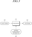
- the processor 310 may select or generate a standard bit allocation table (normalized bit allocation table) without considering hearing data.
- the standard bit allocation table may exist in the memory 130 in the form of a database, for example.
- the standard bit allocation table may be, e.g., a bit allocation table considering psychoacoustics.
- the standard bit allocation table may, e.g., allocate a relatively large quantization bit number to subbands to which many people sensitively react statistically and a relatively small quantization bit number to subbands to which they insensitively react. Statistically, many unspecified people often react to low-band subbands sensitively, so that the standard bit allocation table may be provided to allocate a relatively large quantization bit number to low-band subbands.
- the processor 310 may generate and output a bitstream 340 as a result of performing a compression process on the input audio signal 320.
- the processor 310 may transmit the bitstream 340 to the second electronic device 102 through a communication module (e.g., the communication module 190 of FIG. 1 ).
- the bitstream 340 may be transmitted to the second electronic device 102 through, e.g., a Bluetooth scheme.
- the bitstream may be transmitted to the second electronic device 102 via, e.g., an advanced audio distribution profile (A2DP).
- A2DP advanced audio distribution profile
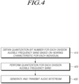
- FIG. 4 is a flowchart illustrating an operation in which a first electronic device 101 quantizes an audio signal according to an embodiment.
- the first electronic device 101 may obtain a quantization bit number based on hearing characteristics for each division audible frequency band.
- the division audible frequency band may mean, e.g., a specific frequency band obtained by dividing the audible frequency band by a predetermined number.
- the division audible frequency band may also be referred to as a subband.
- the first electronic device 101 may obtain the quantization bit number to perform quantization for each division audible frequency using either the first bit allocation table or the second bit allocation table.
- the first electronic device 101 may perform quantization using the quantization bit number corresponding to the division audio signal, which is an audio signal for each division audible frequency band.
- the quantization bit number may mean the quantization bit number for each division audible frequency obtained by the first bit allocation table or the second bit allocation table generated in operation 410.
- the first electronic device 101 may perform quantization on the division audio signal according to the quantization bit number, for example.
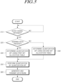
- the first electronic device 101 may receive an audio signal.
- the audio signal may be, e.g., an audio signal generated by execution of a music player.
- the audio signal may include a digital audio signal.
- the audio signal may be an audio signal modulated by a pulse code scheme.
- the first electronic device 101 may determine whether hearing data is present.
- the hearing data may be, e.g., hearing characteristic information about the user measured by a hearing measurement app of the first electronic device 101.
- the hearing data may be, e.g., hearing characteristic information arbitrarily input by the user without measuring by the hearing measurement app.
- the hearing data may be, e.g., information indicating the subband of sound to which the user is sensitive in the audible frequency band.
- the hearing data may be any one of an average value of results measured by the hearing measurement app or a result measured by the user using the hearing measurement app most recently.
- the first electronic device 101 may analyze the hearing data.
- the first electronic device 101 may analyze the bands to which the user is sensitive among the division audible frequency bands in relation to the user's hearing characteristics indicated by the hearing data.
- the first electronic device 101 may select the second bit allocation table stored in the memory 130.
- the second bit allocation table may mean, e.g., the standard bit allocation table of FIG. 3 . Accordingly, since the first electronic device 101 does not need to select or generate a first bit allocation table reflecting hearing data, the computation efficiency or transmission efficiency may be increased.
- the first electronic device 101 may compare the first bit allocation table and the second bit allocation table and then determine which bit allocation table is to be used to perform quantization.
- a characteristic bit allocation table generated based on hearing data of the user sensitive to a low-band may be substantially the same as the standard bit allocation table.
- the first electronic device 101 may compare, e.g., allocation bits for each subband of the characteristic bit allocation table and allocation bits for each subband of the standard bit allocation table.
- the first electronic device 101 may compare, e.g., a predetermined weight for each subband according to the user's hearing data with a predetermined weight used to generate the standard bit allocation table.
- the first electronic device 101 may compress each division audio signal using the quantization bit number determined for each division audible frequency band. For example, if the first electronic device 101 quantizes each division audio signal using the first bit allocation table, a relatively large number of quantization bit strings may be generated in subbands (e.g., mid-band or high-band subbands) to which the user sensitively reacts. For example, if the first electronic device 101 quantizes each division audio signal using the second bit allocation table, a relatively large number of quantization bit strings may be generated in a low-band subband.
- subbands e.g., mid-band or high-band subbands
- the first electronic device 101 may configure the bitstream to include the quantization bit strings generated by performing quantization for each division audio signal in operation 560.
- the first electronic device 101 may transmit the bitstream to the second electronic device 102.
- the first electronic device 101 may transmit the bitstream to the second electronic device 102 through a communication module (e.g., the communication module 190 of FIG. 1 ).
- the first electronic device 101 may transmit the bitstream in a Bluetooth scheme through a wireless communication module (e.g., the wireless communication module 192 of FIG. 1 ).
- Each operation illustrated in FIG. 5 is not limited to the illustrated order, but the order may be changed as necessary.
- the operation in which the first electronic device 101 establishes the radio channel with the second electronic device 102 may be performed before operation 560.
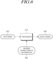
- a bitstream 620 may be input to the processor 610 included in the second electronic device 102.
- the bitstream 620 may be a signal obtained by compressing the audio signal 320 (e.g., the audio signal 320 of FIG. 3 ) through quantization in the first electronic device 101.
- the operation performed by the processor 610 may correspond to all or some of the operations performed by the processor 310 (e.g., the processor 310 of FIG. 3 ) of the first electronic device 101.
- the processor 610 may, e.g., perform inverse-quantization on the input bitstream 620.
- the decompression including the inverse-quantization may be performed, e.g., software-wise by the processor 610 or hardware-wise through a separate decoder unit.
- the processor 610 may be implemented as, e.g., an audio signal processor (e.g., the audio signal processor 240 of FIG. 2 ).
- the hearing characteristic information 630 may be information stored in the bitstream 620 received from the first electronic device 101.
- the processor 610 may analyze the received bitstream 620 to obtain hearing characteristic information 630 stored in the bitstream 620.
- the processor 610 may analyze the received bitstream 620 to obtain bit allocation information used when quantizing the audio signal 320.
- the hearing characteristic information 630 may be information separately obtained from the first electronic device 101 through the radio channel.
- the hearing characteristic information 630 may be information stored by the second electronic device 102 in the form of a database.
- the bitstream 620 may be inverse-quantized using the second bit allocation table (e.g., the second bit allocation table in FIG. 3 ) and reconstructed to the audio signal 640.
- the standard bit allocation table may be information stored in the memory by the second electronic device 102 or information received by the first electronic device 101.
- the processor 610 may select either the first bit allocation table or the second bit allocation table to perform inverse-quantization using the inverse-quantization bit number corresponding to the bitstream 620 for each audible frequency band. If inverse-quantization is performed for each division audible frequency band and then synthesized as one signal, an audio signal 640 may be generated.
- the generated audio signal 640 may be, e.g., an audio signal modulated by a pulse code modulation scheme.
- the audio signal 640 may be converted into an analog signal in an audio module provided in the second electronic device 102 and then output through a voice output device.
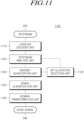
- FIG. 7 is a flowchart illustrating control for inverse-quantizing an audio signal by a second electronic device 102 according to an embodiment.
- the second electronic device 102 may analyze a bitstream received from the first electronic device 101.
- the second electronic device 102 may receive the bitstream through the radio channel established with the first electronic device 101.
- the second electronic device 102 may determine the inverse-quantization bit number to perform inverse-quantization for each division audio signal included in the bitstream for each division audible frequency band by using the first bit allocation table.
- the second electronic device 102 may determine the inverse-quantization bit number to perform inverse-quantization for each division audio signal included in the bitstream for each division audible frequency band by using the second bit allocation table.
- the second electronic device 102 may perform inverse-quantization for each division audio signal included in the bitstream for each division audible frequency band using the bit number to perform inverse-quantization determined for each division audible frequency band.
- the signal classification unit 930 may divide the audio signal in the frequency domain into division audible frequency bands of predetermined intervals.
- the audible frequency bands divided at predetermined intervals may be referred to as subbands.
- the predetermined intervals may be, e.g., intervals obtained by dividing the audible frequency bands by n.
- the audible frequency band is divided into n subbands, the first subband (Sb #1), the second subband (Sb #2), and the like in the order of the high-frequency band from the low-frequency band....
- nth subband Sb #n it may be referred to as an nth subband Sb #n.
- the respective intervals of the subbands may be the same or different.
- the n division subbands may be arranged consecutively in the frequency domain.
- the n subbands may be arranged in series in the order from the lowest-band subband to the highest-band subband.
- the bit allocation selection unit 940 may allocate the quantization bit number for each division audible frequency band by selecting, e.g., a bit allocation table.
- the bit allocation table may include, e.g., the first bit allocation table or the second bit allocation table.
- the first bit allocation table may be, e.g., a bit allocation table considering the hearing characteristics of the user. For example, if the user is sensitive to a high-band as a result of the hearing measurement, the first bit allocation table may be a table where a relatively large quantization bit number is allocated to a high-band frequency. For example, if the user is sensitive to a mid-band as a result of the hearing measurement, the first bit allocation table may be a table where a relatively large quantization bit number is allocated to a mid-band frequency. For example, if the user is sensitive to a low-band as a result of the hearing measurement, the first bit allocation table may be a table where a relatively large quantization bit number is allocated to a low-band frequency.
- the largest quantization bit number may be allocated to the nth subband Sb #n having the highest priority and, by reducing as many bits as allocated to the nth subband Sb #n from the total allocation bit number, as large a quantization bit number as the corresponding weight may be allocated to the subband having the next highest priority. By repeating such a process, bits may be repeatedly allocated until the total number of bits is exhausted.
- the bit allocation selection unit 940 may limit the bit number allocated to each subband not to exceed an allowed bit number (e.g., the total number of bits to be transmitted), determining the quantization bit number to be finally allocated.
- the quantization bit number to be allocated may be affected, e.g., by a communication environment between the first electronic device 101 and the second electronic device 102.
- the quantization unit 950 may quantize the audio signal by the quantization bit number allocated for each subband according to the bit allocation table selected by the bit allocation selection unit 940.
- the quantization unit 950 may perform quantization through a computation according to the quantization bit number allocated for each subband.
- the quantization unit 950 may perform quantization on the corresponding division audio signal by the quantization bit number for each subband.
- the quantization unit 950 may quantize the Norm value for each subband.
- the Norm value may be quantized in various ways such as vector quantization, scalar quantization, TCQ, and lattice vector quantization (LVQ).
- the quantization unit 950 may additionally perform lossless encoding to enhance additional encoding efficiency.
- the lossless coder unit 960 may perform lossless encoding on the result quantized by the quantization unit 950.
- a trellis coded quantizer TCQ
- a uniform scalar quantizer USQ
- a factorial pulse coder FPC
- an analog vector quantizer AVQ
- PVQ predictive vector quantizer
- various encoding techniques may be applied according to the environment where the corresponding codec is mounted or to the needs of the user.
- Information about the audio signal encoded by the lossless coder unit 960 may be included in the bitstream 340.
- the lossless coder unit 960 may hierarchically perform lossless encoding on the audio signal quantized by the quantization unit 950.
- the lossless coder unit 960 may, e.g., perform lossless encoding with a group of codes corresponding to the highest bits as the highest layer, and sequentially perform lossless encoding with a group of codes corresponding to the lower bits as the lower layers.
- the lossless coder unit 960 may perform encoding on the audio signal considering, e.g., duplicate values and frequency for each subband.
- the bitstream 340 encoded by the lossless coder unit 960 may be transmitted to the second electronic device 102.
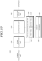
- FIG. 10 is a block diagram illustrating part 1000 of an encoder of a first electronic device according to an embodiment.
- FIG. 10 parts related to the disclosure in the encoder of FIG. 9 are illustrated in more detail. Accordingly, all or some of the components of FIG. 10 may correspond to the components of FIG. 9 . No duplicate description of the components is given below.
- the audio signal transformed into the frequency domain in the domain transformation unit 1020 may be input to the signal classification unit 1030.
- the signal classification unit 1030 may correspond to the signal classification unit (e.g., the signal classification unit 930 of FIG. 7 ).
- the audio signal may be divided for each predetermined division audible frequency band for the input audio signal.
- the audio signal may be divided into n subbands including a first subband Sb #1, a second subband Sb #2, a third subband Sb #3, ...., an nth subband Sb #n.
- the n division subbands may be continuously arranged in the frequency domain.
- the n subbands may be arranged in series in the order from the lowest-band subband to the highest-band subband.
- the hearing data (e.g., the hearing data of FIG. 3 ) may be stored in the memory 1080 in the form of a database 1081.
- the hearing data may be represented by Table 1.
- Table 1 is a table in which the audible frequency band is divided into n subbands Sb, and hearing measurement results according to each subband Sb are summarized.
- the hearing measurement result (hearing loss) for each subband may be recorded through the hearing measurement app (e.g., the hearing measurement app of FIG. 3 ).
- the hearing measurement result may indicate any one of 'very good,' 'good,' or 'average.
- the hearing measurement result of the first subband Sb #1 may be represented as HL #1
- the hearing measurement result of the second subband Sb #2 may be represented as HL #2
- the hearing measurement result of the third subband Sb #3 may be represented as HL #3
- the hearing measurement result of the nth subband Sb #n may be represented as HL #n.
- a different weight may be set according to the hearing measurement result for each subband.
- the weight may be determined according to the hearing measurement result (hearing loss). For example, when the hearing measurement result is 'very good,' a weight of w a may be determined. For example, when the hearing measurement result is 'good,' a weight of w b may be determined. For example, when the hearing measurement result is 'average,' a weight of w c may be determined.
- w a , w d , and w c may have a relationship: w a ⁇ w b ⁇ w c .
- the user may, by himself/herself, input the hearing measurement result for each of his/her division audible frequencies without performing hearing measurement.
- hearing data considering the hearing characteristics for each user may be stored, as a database 1081, in the memory 1080.
- the processor may generate a characteristic bit allocation table considering hearing data.
- Table 2 exemplarily shows that the processor 310 generates a characteristic bit allocation table by reflecting hearing data.
- Subband (Sb) basis bit allocation value (basis bit allocation value) weight assigned (weight) characterized bit allocation value (characterized bit allocation value) first subband (Sb #1) A 1 w a1 /w b /w c (w#1) A 1 ' second subband (Sb #2) A 2 w a /w b /w c (w#2) A 2 ' third subband (Sb #3) A 3 w a /w b /w c (w#3) A 3 ' .... .... .... > nth subband (Sb #n) A n w a1 /w b /w c (w#n) A n '
- Table 2 is a table in which the frequency band is divided into m subbands Sb, a weight is assigned to the basic bit allocation value for each subband according to the hearing measurement result of each subband Sb to derive a characteristic allocation bit value (characterized bit allocation value).
- the audible frequency band may be divided into m subbands. m and n may be the same or different.
- the table constituted of the characteristic allocation bit values may be referred to as a first bit allocation table.
- the weight for each subband Sb may be determined as any one value among w a , w b , or w c according to the hearing characteristics of the user.
- the characteristic allocation bit value (characterized bit allocation value) may be derived by assigning a weight for each subband Sb according to the user's hearing measurement result to each basic bit allocation value for each subband Sb.
- the characteristic allocation bit value (characterized bit allocation value) may be, e.g., a result derived by multiplying the bit allocation value by the weight.
- the characteristic allocation bit value may be derived by performing computation on the bit allocation value and the weight in variously defined manners.
- the domain transformation unit 1160 may transform the area of the bitstream subjected to inverse-quantization.
- the domain transformation unit 1160 may transform a bitstream of a frequency domain into a time domain.
- the transformation may be performed using, e.g., an inverse Fourier transform scheme.
- the inverse fast Fourier transform (IFFT) scheme may include an inverse fast Fourier transform (IFFT).
- IFFT inverse fast Fourier transform
- the domain transformation unit 1160 may transform the decoded bitstream into a time domain to generate a reconstructed audio signal.
- the domain transformation unit 1160 may synthesize the bitstream inverse-quantized for each division audible frequency.
- the audio signal 640 generated through the domain transformation unit 1160 may be transformed into an analog audio signal in a digital signal processor or ADC provided in the second electronic device 102 and then output to the sound output device.
- An embodiment of the disclosure may provide a device and method for minimizing quantization noise by reflecting the user's individual hearing characteristics in quantizing or inverse-quantizing an audio signal.
- a method for controlling a first electronic device 101 may comprise an operation 410 of obtaining a quantization bit number for each division audible frequency band dividing an audible frequency band based on a preset user's hearing characteristic, an operation 420 of performing quantization using a quantization bit number corresponding to an audio signal for each division audible frequency band extracted from an audio signal 320 output by reproduction of an audio content, and an operation 430 of generating an audio signal quantized for each division audible frequency band as a bitstream 340 and transmitting the bitstream to a second electronic device 102 through a radio channel.
- the method for controlling the first electronic device 101 may comprise an operation of setting the user's hearing characteristic 330 by performing hearing measurement for each division audible frequency band, on the user.
- the method for controlling the first electronic device 101 may comprise an operation 530 of generating a quantization bit allocation table in which the quantization bit number for each division audible frequency band is updated by reflecting the preset user's hearing characteristic 330.
- the method for controlling the first electronic device 101 may comprise an operation 530, 540 of selecting one quantization bit allocation table from among a plurality of generated quantization bit allocation tables.
- the method for controlling the first electronic device 101 may comprise an operation of lossless-encoding the audio signal quantized for each division audible frequency band.
- a method for controlling a second electronic device 102 may comprise an operation 710, 820 of analyzing a bitstream 340, 620 received from a first electronic device 101, an operation 720 of obtaining an inverse-quantization bit number for each division audible frequency band included in the bitstream, an operation 730 of performing inverse-quantization on the bitstream 340, 620 for each audible frequency band using the inverse-quantization bit number, and an operation 740 of outputting an audio signal 640 generated by the inverse-quantization.
- the inverse-quantization bit number may correspond to a quantization bit number for each audible frequency band used for the first electronic device 101 to perform quantization on an audio signal 320.
- the method for controlling the second electronic device 102 may comprise an operation of requesting information about a user's hearing characteristic 630 required to perform inverse-quantization, from the first device 101.
- the method for controlling the second electronic device 102 may comprise an operation of obtaining the information 630 about the user's hearing characteristic present, from a first electronic device 101 and an operation of generating an inverse-quantization bit allocation table for each division audible frequency band from the obtained information 630.
- a first electronic device 101 may comprise at least one processor 120, 310 and a communication module 190.
- the at least one processor 120, 310 may obtain a quantization bit number for each division audible frequency band dividing an audible frequency band based on a preset user's hearing characteristic 330, perform quantization using a quantization bit number corresponding to an audio signal for each division audible frequency band extracted from an audio signal output by reproduction of an audio content, and generate an audio signal quantized for each division audible frequency band as one bitstream 340 and transmit the bitstream to a second electronic device 102 through a radio channel.
- the at least one processor 120, 310 may set the user's hearing characteristic 330 by performing hearing measurement for each division audible frequency band, on the user.
- the at least one processor 120, 310 may generate a quantization bit allocation table in which the quantization bit number for each division audible frequency band is updated by reflecting the preset user's hearing characteristic 330.
- the at least one processor 120, 310 may select one quantization bit allocation table from among a plurality of generated quantization bit allocation tables.
- the at least one processor 120, 310 may lossless-encode the audio signal quantized for each division audible frequency band.
- a second electronic device 102 may comprise at least one processor 610 and a communication module.
- the at least one processor 610 may analyze a bitstream received from a first electronic device 101, obtain an inverse-quantization bit number for each division audible frequency band included in the bitstream 340, 620, perform inverse-quantization on the bitstream 340, 620 for each audible frequency band using the inverse-quantization bit number, and output an audio signal 640 generated by the inverse-quantization.
- the inverse-quantization bit number may correspond to a quantization bit number for each audible frequency band used for the first electronic device 101 to perform quantization on an audio signal 320.
- the at least one processor 610 of the second electronic device 102 may request information 330, 630 about a user's hearing characteristic required to perform inverse-quantization, from the first electronic device 101.
- the at least one processor 610 of the second electronic device 102 may obtain the information 330 about the user's hearing characteristic present, from the first electronic device 101, and generate an inverse-quantization bit allocation table for each division audible frequency band from the obtained information 330, 630.
- the electronic device 101, 102 may select a quantization model considering a communication environment and quantize or inverse-quantize the audio signal 320, 630.
- the electronic device 101, 102 may minimize the quantization noise generated when the audio signal 320, 630 is quantized or inverse-quantized based on the user's hearing data 330, 630, and provide an audio signal with the optimal sound quality.
- the electronic device may be one of various types of electronic devices.
- the electronic devices may include, for example, a portable communication device (e.g., a smartphone), a computer device, a portable multimedia device, a portable medical device, a camera, a wearable device, or a home appliance. According to an embodiment of the disclosure, the electronic devices are not limited to those described above.
- each of such phrases as “A or B,” “at least one of A and B,” “at least one of A or B,” “A, B, or C,” “at least one of A, B, and C,” and “at least one of A, B, or C,” may include any one of, or all possible combinations of the items enumerated together in a corresponding one of the phrases.
- such terms as “1st” and “2nd,” or “first” and “second” may be used to simply distinguish a corresponding component from another, and does not limit the components in other aspect (e.g., importance or order).
- an element e.g., a first element
- the element may be coupled with the other element directly (e.g., wiredly), wirelessly, or via a third element.
- module may include a unit implemented in hardware, software, or firmware, and may interchangeably be used with other terms, for example, “logic,” “logic block,” “part,” or “circuitry”.
- a module may be a single integral component, or a minimum unit or part thereof, adapted to perform one or more functions.
- the module may be implemented in a form of an application-specific integrated circuit (ASIC).
- ASIC application-specific integrated circuit
- Various embodiments as set forth herein may be implemented as software (e.g., the program 140) including one or more instructions that are stored in a storage medium (e.g., internal memory 136 or external memory 138) that is readable by a machine (e.g., the electronic device 101).
- a processor e.g., the processor 120
- the machine e.g., the electronic device 101
- the one or more instructions may include a code generated by a complier or a code executable by an interpreter.
- the machine-readable storage medium may be provided in the form of a non-transitory storage medium.
- non-transitory simply means that the storage medium is a tangible device, and does not include a signal (e.g., an electromagnetic wave), but this term does not differentiate between where data is semi-permanently stored in the storage medium and where the data is temporarily stored in the storage medium.
- a method may be included and provided in a computer program product.
- the computer program product may be traded as a product between a seller and a buyer.
- the computer program product may be distributed in the form of a machine-readable storage medium (e.g., compact disc read only memory (CD-ROM)), or be distributed (e.g., downloaded or uploaded) online via an application store (e.g., PlayStore TM ), or between two user devices (e.g., smart phones) directly. If distributed online, at least part of the computer program product may be temporarily generated or at least temporarily stored in the machine-readable storage medium, such as memory of the manufacturer's server, a server of the application store, or a relay server.
- CD-ROM compact disc read only memory
- an application store e.g., PlayStore TM
- two user devices e.g., smart phones
- each component e.g., a module or a program of the above-described components may include a single entity or multiple entities, and some of the multiple entities may be separately disposed in different components. According to various embodiments, one or more of the above-described components may be omitted, or one or more other components may be added. Alternatively or additionally, a plurality of components (e.g., modules or programs) may be integrated into a single component. In such a case, according to various embodiments, the integrated component may still perform one or more functions of each of the plurality of components in the same or similar manner as they are performed by a corresponding one of the plurality of components before the integration.
Landscapes
- Physics & Mathematics (AREA)
- Engineering & Computer Science (AREA)
- Spectroscopy & Molecular Physics (AREA)
- Computational Linguistics (AREA)
- Signal Processing (AREA)
- Health & Medical Sciences (AREA)
- Audiology, Speech & Language Pathology (AREA)
- Human Computer Interaction (AREA)
- Acoustics & Sound (AREA)
- Multimedia (AREA)
- Circuit For Audible Band Transducer (AREA)
- Compression, Expansion, Code Conversion, And Decoders (AREA)
Applications Claiming Priority (3)
| Application Number | Priority Date | Filing Date | Title |
|---|---|---|---|
| KR20220132769 | 2022-10-14 | ||
| KR1020220161912A KR20240052588A (ko) | 2022-10-14 | 2022-11-28 | 오디오 신호를 처리하는 전자 장치 및 방법 |
| PCT/KR2023/015590 WO2024080723A1 (ko) | 2022-10-14 | 2023-10-11 | 오디오 신호를 처리하는 전자 장치 및 방법 |
Publications (2)
| Publication Number | Publication Date |
|---|---|
| EP4579656A1 true EP4579656A1 (de) | 2025-07-02 |
| EP4579656A4 EP4579656A4 (de) | 2025-11-12 |
Family
ID=90669887
Family Applications (1)
| Application Number | Title | Priority Date | Filing Date |
|---|---|---|---|
| EP23877650.4A Pending EP4579656A4 (de) | 2022-10-14 | 2023-10-11 | Elektronische vorrichtung und verfahren zur verarbeitung eines audiosignals |
Country Status (4)
| Country | Link |
|---|---|
| US (1) | US20250259637A1 (de) |
| EP (1) | EP4579656A4 (de) |
| CN (1) | CN120019433A (de) |
| WO (1) | WO2024080723A1 (de) |
Family Cites Families (6)
| Publication number | Priority date | Publication date | Assignee | Title |
|---|---|---|---|---|
| JP3334374B2 (ja) * | 1994-10-28 | 2002-10-15 | ソニー株式会社 | ディジタル信号圧縮方法及び装置 |
| JPH08237209A (ja) * | 1994-12-27 | 1996-09-13 | Sony Corp | ディジタルオーディオ信号処理装置 |
| JP2000295110A (ja) * | 1999-04-06 | 2000-10-20 | Matsushita Electric Ind Co Ltd | オーディオ信号符号化装置 |
| KR100707173B1 (ko) * | 2004-12-21 | 2007-04-13 | 삼성전자주식회사 | 저비트율 부호화/복호화방법 및 장치 |
| EP3598440B1 (de) * | 2018-07-20 | 2022-04-20 | Mimi Hearing Technologies GmbH | Systeme und verfahren zur codierung eines audiosignals mit personalisierten psychoakustischen modellen |
| KR20220048252A (ko) * | 2020-10-12 | 2022-04-19 | 한국전자통신연구원 | 학습 모델을 이용한 오디오 신호의 부호화 및 복호화 방법 및 장치와 학습 모델의 트레이닝 방법 및 장치 |
-
2023
- 2023-10-11 CN CN202380072379.4A patent/CN120019433A/zh active Pending
- 2023-10-11 WO PCT/KR2023/015590 patent/WO2024080723A1/ko not_active Ceased
- 2023-10-11 EP EP23877650.4A patent/EP4579656A4/de active Pending
-
2025
- 2025-04-01 US US19/097,024 patent/US20250259637A1/en active Pending
Also Published As
| Publication number | Publication date |
|---|---|
| US20250259637A1 (en) | 2025-08-14 |
| CN120019433A (zh) | 2025-05-16 |
| WO2024080723A1 (ko) | 2024-04-18 |
| EP4579656A4 (de) | 2025-11-12 |
Similar Documents
| Publication | Publication Date | Title |
|---|---|---|
| US10580424B2 (en) | Perceptual audio coding as sequential decision-making problems | |
| US10966033B2 (en) | Systems and methods for modifying an audio signal using custom psychoacoustic models | |
| KR20190130455A (ko) | 콘볼루션 뉴럴 네트워크 모델 구축 방법 및 시스템 | |
| CN110557179B (zh) | 用于波束成形接收方的装置及方法 | |
| US10455335B1 (en) | Systems and methods for modifying an audio signal using custom psychoacoustic models | |
| US10734006B2 (en) | Audio coding based on audio pattern recognition | |
| US10573331B2 (en) | Cooperative pyramid vector quantizers for scalable audio coding | |
| US12254241B2 (en) | Method for preventing duplicate application of audio effects to audio data and electronic device supporting the same | |
| EP4579656A1 (de) | Elektronische vorrichtung und verfahren zur verarbeitung eines audiosignals | |
| KR20220125026A (ko) | 오디오 처리 방법 및 이를 포함하는 전자 장치 | |
| US12374346B2 (en) | Electronic device for performing audio streaming and operating method thereof | |
| US10586546B2 (en) | Inversely enumerated pyramid vector quantizers for efficient rate adaptation in audio coding | |
| KR20240052588A (ko) | 오디오 신호를 처리하는 전자 장치 및 방법 | |
| KR102838102B1 (ko) | 음질 향상 방법 및 그 장치 | |
| EP4567789A1 (de) | Elektronische vorrichtung und verfahren zur adaptiven verarbeitung eines audiobitstroms und nichttransitorisches computerlesbares speichermedium | |
| US10559315B2 (en) | Extended-range coarse-fine quantization for audio coding | |
| US12341838B2 (en) | Electronic device and sink device for transmitting and receiving audio packet, and operating methods thereof | |
| KR20260040916A (ko) | 심리음향모델을 이용한 오디오 신호 처리 방법 및 이를 수행하는 전자 장치 | |
| US20250246198A1 (en) | Electronic device for acquiring voice signals and operating method thereof | |
| EP4459970B1 (de) | Elektronische vorrichtungen zur verbesserung der klangqualität und zur reduzierung des stromverbrauchs | |
| US20250239252A1 (en) | Electronic device and method for generating vibration sound signal | |
| KR20240050955A (ko) | 오디오 비트스트림을 적응적으로 처리하는 전자 장치, 방법, 및 비일시적 컴퓨터 판독가능 저장 매체 | |
| KR102862970B1 (ko) | 오디오 데이터 처리 방법 및 이를 지원하는 전자 장치 | |
| CN118303037A (zh) | 用于执行音频流式传输的电子设备及其操作方法 | |
| KR20230072355A (ko) | 오디오 스트리밍을 수행하는 전자 장치 및 그 동작 방법 |
Legal Events
| Date | Code | Title | Description |
|---|---|---|---|
| STAA | Information on the status of an ep patent application or granted ep patent |
Free format text: STATUS: THE INTERNATIONAL PUBLICATION HAS BEEN MADE |
|
| PUAI | Public reference made under article 153(3) epc to a published international application that has entered the european phase |
Free format text: ORIGINAL CODE: 0009012 |
|
| STAA | Information on the status of an ep patent application or granted ep patent |
Free format text: STATUS: REQUEST FOR EXAMINATION WAS MADE |
|
| 17P | Request for examination filed |
Effective date: 20250327 |
|
| AK | Designated contracting states |
Kind code of ref document: A1 Designated state(s): AL AT BE BG CH CY CZ DE DK EE ES FI FR GB GR HR HU IE IS IT LI LT LU LV MC ME MK MT NL NO PL PT RO RS SE SI SK SM TR |
|
| A4 | Supplementary search report drawn up and despatched |
Effective date: 20251014 |
|
| RIC1 | Information provided on ipc code assigned before grant |
Ipc: G10L 19/032 20130101AFI20251008BHEP Ipc: G10L 19/02 20130101ALN20251008BHEP |
|
| DAV | Request for validation of the european patent (deleted) | ||
| DAX | Request for extension of the european patent (deleted) |