EP4579433A1 - Elektronische vorrichtung zur einstellung eines audiosignals im zusammenhang mit einem durch eine anzeige angezeigten objekt und verfahren dafür - Google Patents
Elektronische vorrichtung zur einstellung eines audiosignals im zusammenhang mit einem durch eine anzeige angezeigten objekt und verfahren dafür Download PDFInfo
- Publication number
- EP4579433A1 EP4579433A1 EP23868515.0A EP23868515A EP4579433A1 EP 4579433 A1 EP4579433 A1 EP 4579433A1 EP 23868515 A EP23868515 A EP 23868515A EP 4579433 A1 EP4579433 A1 EP 4579433A1
- Authority
- EP
- European Patent Office
- Prior art keywords
- electronic device
- acoustic signal
- external object
- display
- volume
- Prior art date
- Legal status (The legal status is an assumption and is not a legal conclusion. Google has not performed a legal analysis and makes no representation as to the accuracy of the status listed.)
- Pending
Links
Images




Classifications
-
- G—PHYSICS
- G06—COMPUTING OR CALCULATING; COUNTING
- G06F—ELECTRIC DIGITAL DATA PROCESSING
- G06F3/00—Input arrangements for transferring data to be processed into a form capable of being handled by the computer; Output arrangements for transferring data from processing unit to output unit, e.g. interface arrangements
- G06F3/01—Input arrangements or combined input and output arrangements for interaction between user and computer
- G06F3/048—Interaction techniques based on graphical user interfaces [GUI]
- G06F3/0484—Interaction techniques based on graphical user interfaces [GUI] for the control of specific functions or operations, e.g. selecting or manipulating an object, an image or a displayed text element, setting a parameter value or selecting a range
- G06F3/04842—Selection of displayed objects or displayed text elements
-
- G—PHYSICS
- G06—COMPUTING OR CALCULATING; COUNTING
- G06F—ELECTRIC DIGITAL DATA PROCESSING
- G06F3/00—Input arrangements for transferring data to be processed into a form capable of being handled by the computer; Output arrangements for transferring data from processing unit to output unit, e.g. interface arrangements
- G06F3/16—Sound input; Sound output
- G06F3/165—Management of the audio stream, e.g. setting of volume, audio stream path
-
- G—PHYSICS
- G06—COMPUTING OR CALCULATING; COUNTING
- G06F—ELECTRIC DIGITAL DATA PROCESSING
- G06F1/00—Details not covered by groups G06F3/00 - G06F13/00 and G06F21/00
- G06F1/16—Constructional details or arrangements
- G06F1/1613—Constructional details or arrangements for portable computers
- G06F1/163—Wearable computers, e.g. on a belt
-
- G—PHYSICS
- G06—COMPUTING OR CALCULATING; COUNTING
- G06F—ELECTRIC DIGITAL DATA PROCESSING
- G06F3/00—Input arrangements for transferring data to be processed into a form capable of being handled by the computer; Output arrangements for transferring data from processing unit to output unit, e.g. interface arrangements
- G06F3/01—Input arrangements or combined input and output arrangements for interaction between user and computer
- G06F3/011—Arrangements for interaction with the human body, e.g. for user immersion in virtual reality
-
- G—PHYSICS
- G06—COMPUTING OR CALCULATING; COUNTING
- G06F—ELECTRIC DIGITAL DATA PROCESSING
- G06F3/00—Input arrangements for transferring data to be processed into a form capable of being handled by the computer; Output arrangements for transferring data from processing unit to output unit, e.g. interface arrangements
- G06F3/01—Input arrangements or combined input and output arrangements for interaction between user and computer
- G06F3/011—Arrangements for interaction with the human body, e.g. for user immersion in virtual reality
- G06F3/013—Eye tracking input arrangements
-
- G—PHYSICS
- G06—COMPUTING OR CALCULATING; COUNTING
- G06F—ELECTRIC DIGITAL DATA PROCESSING
- G06F3/00—Input arrangements for transferring data to be processed into a form capable of being handled by the computer; Output arrangements for transferring data from processing unit to output unit, e.g. interface arrangements
- G06F3/01—Input arrangements or combined input and output arrangements for interaction between user and computer
- G06F3/048—Interaction techniques based on graphical user interfaces [GUI]
- G06F3/0484—Interaction techniques based on graphical user interfaces [GUI] for the control of specific functions or operations, e.g. selecting or manipulating an object, an image or a displayed text element, setting a parameter value or selecting a range
- G06F3/04847—Interaction techniques to control parameter settings, e.g. interaction with sliders or dials
-
- G—PHYSICS
- G06—COMPUTING OR CALCULATING; COUNTING
- G06F—ELECTRIC DIGITAL DATA PROCESSING
- G06F3/00—Input arrangements for transferring data to be processed into a form capable of being handled by the computer; Output arrangements for transferring data from processing unit to output unit, e.g. interface arrangements
- G06F3/16—Sound input; Sound output
- G06F3/167—Audio in a user interface, e.g. using voice commands for navigating, audio feedback
-
- H—ELECTRICITY
- H04—ELECTRIC COMMUNICATION TECHNIQUE
- H04L—TRANSMISSION OF DIGITAL INFORMATION, e.g. TELEGRAPHIC COMMUNICATION
- H04L67/00—Network arrangements or protocols for supporting network services or applications
- H04L67/01—Protocols
- H04L67/131—Protocols for games, networked simulations or virtual reality
-
- H—ELECTRICITY
- H04—ELECTRIC COMMUNICATION TECHNIQUE
- H04M—TELEPHONIC COMMUNICATION
- H04M1/00—Substation equipment, e.g. for use by subscribers
- H04M1/72—Mobile telephones; Cordless telephones, i.e. devices for establishing wireless links to base stations without route selection
- H04M1/724—User interfaces specially adapted for cordless or mobile telephones
- H04M1/72448—User interfaces specially adapted for cordless or mobile telephones with means for adapting the functionality of the device according to specific conditions
- H04M1/72454—User interfaces specially adapted for cordless or mobile telephones with means for adapting the functionality of the device according to specific conditions according to context-related or environment-related conditions
-
- H—ELECTRICITY
- H04—ELECTRIC COMMUNICATION TECHNIQUE
- H04R—LOUDSPEAKERS, MICROPHONES, GRAMOPHONE PICK-UPS OR LIKE ACOUSTIC ELECTROMECHANICAL TRANSDUCERS; ELECTRIC HEARING AIDS; PUBLIC ADDRESS SYSTEMS
- H04R1/00—Details of transducers, loudspeakers or microphones
- H04R1/20—Arrangements for obtaining desired frequency or directional characteristics
- H04R1/32—Arrangements for obtaining desired frequency or directional characteristics for obtaining desired directional characteristic only
- H04R1/326—Arrangements for obtaining desired frequency or directional characteristics for obtaining desired directional characteristic only for microphones
-
- H—ELECTRICITY
- H04—ELECTRIC COMMUNICATION TECHNIQUE
- H04R—LOUDSPEAKERS, MICROPHONES, GRAMOPHONE PICK-UPS OR LIKE ACOUSTIC ELECTROMECHANICAL TRANSDUCERS; ELECTRIC HEARING AIDS; PUBLIC ADDRESS SYSTEMS
- H04R1/00—Details of transducers, loudspeakers or microphones
- H04R1/20—Arrangements for obtaining desired frequency or directional characteristics
- H04R1/32—Arrangements for obtaining desired frequency or directional characteristics for obtaining desired directional characteristic only
- H04R1/40—Arrangements for obtaining desired frequency or directional characteristics for obtaining desired directional characteristic only by combining a number of identical transducers
- H04R1/406—Arrangements for obtaining desired frequency or directional characteristics for obtaining desired directional characteristic only by combining a number of identical transducers microphones
-
- H—ELECTRICITY
- H04—ELECTRIC COMMUNICATION TECHNIQUE
- H04R—LOUDSPEAKERS, MICROPHONES, GRAMOPHONE PICK-UPS OR LIKE ACOUSTIC ELECTROMECHANICAL TRANSDUCERS; ELECTRIC HEARING AIDS; PUBLIC ADDRESS SYSTEMS
- H04R3/00—Circuits for transducers
- H04R3/005—Circuits for transducers for combining the signals of two or more microphones
-
- H—ELECTRICITY
- H04—ELECTRIC COMMUNICATION TECHNIQUE
- H04S—STEREOPHONIC SYSTEMS
- H04S7/00—Indicating arrangements; Control arrangements, e.g. balance control
- H04S7/30—Control circuits for electronic adaptation of the sound field
- H04S7/302—Electronic adaptation of stereophonic sound system to listener position or orientation
- H04S7/303—Tracking of listener position or orientation
-
- G—PHYSICS
- G10—MUSICAL INSTRUMENTS; ACOUSTICS
- G10L—SPEECH ANALYSIS TECHNIQUES OR SPEECH SYNTHESIS; SPEECH RECOGNITION; SPEECH OR VOICE PROCESSING TECHNIQUES; SPEECH OR AUDIO CODING OR DECODING
- G10L21/00—Speech or voice signal processing techniques to produce another audible or non-audible signal, e.g. visual or tactile, in order to modify its quality or its intelligibility
- G10L21/02—Speech enhancement, e.g. noise reduction or echo cancellation
- G10L21/0208—Noise filtering
- G10L21/0216—Noise filtering characterised by the method used for estimating noise
- G10L2021/02161—Number of inputs available containing the signal or the noise to be suppressed
- G10L2021/02166—Microphone arrays; Beamforming
-
- H—ELECTRICITY
- H04—ELECTRIC COMMUNICATION TECHNIQUE
- H04M—TELEPHONIC COMMUNICATION
- H04M1/00—Substation equipment, e.g. for use by subscribers
- H04M1/60—Substation equipment, e.g. for use by subscribers including speech amplifiers
- H04M1/6008—Substation equipment, e.g. for use by subscribers including speech amplifiers in the transmitter circuit
-
- H—ELECTRICITY
- H04—ELECTRIC COMMUNICATION TECHNIQUE
- H04M—TELEPHONIC COMMUNICATION
- H04M1/00—Substation equipment, e.g. for use by subscribers
- H04M1/60—Substation equipment, e.g. for use by subscribers including speech amplifiers
- H04M1/6016—Substation equipment, e.g. for use by subscribers including speech amplifiers in the receiver circuit
-
- H—ELECTRICITY
- H04—ELECTRIC COMMUNICATION TECHNIQUE
- H04M—TELEPHONIC COMMUNICATION
- H04M2250/00—Details of telephonic subscriber devices
- H04M2250/52—Details of telephonic subscriber devices including functional features of a camera
-
- H—ELECTRICITY
- H04—ELECTRIC COMMUNICATION TECHNIQUE
- H04R—LOUDSPEAKERS, MICROPHONES, GRAMOPHONE PICK-UPS OR LIKE ACOUSTIC ELECTROMECHANICAL TRANSDUCERS; ELECTRIC HEARING AIDS; PUBLIC ADDRESS SYSTEMS
- H04R1/00—Details of transducers, loudspeakers or microphones
- H04R1/02—Casings; Cabinets ; Supports therefor; Mountings therein
- H04R1/028—Casings; Cabinets ; Supports therefor; Mountings therein associated with devices performing functions other than acoustics, e.g. electric candles
-
- H—ELECTRICITY
- H04—ELECTRIC COMMUNICATION TECHNIQUE
- H04R—LOUDSPEAKERS, MICROPHONES, GRAMOPHONE PICK-UPS OR LIKE ACOUSTIC ELECTROMECHANICAL TRANSDUCERS; ELECTRIC HEARING AIDS; PUBLIC ADDRESS SYSTEMS
- H04R2201/00—Details of transducers, loudspeakers or microphones covered by H04R1/00 but not provided for in any of its subgroups
- H04R2201/40—Details of arrangements for obtaining desired directional characteristic by combining a number of identical transducers covered by H04R1/40 but not provided for in any of its subgroups
- H04R2201/401—2D or 3D arrays of transducers
-
- H—ELECTRICITY
- H04—ELECTRIC COMMUNICATION TECHNIQUE
- H04R—LOUDSPEAKERS, MICROPHONES, GRAMOPHONE PICK-UPS OR LIKE ACOUSTIC ELECTROMECHANICAL TRANSDUCERS; ELECTRIC HEARING AIDS; PUBLIC ADDRESS SYSTEMS
- H04R2430/00—Signal processing covered by H04R, not provided for in its groups
- H04R2430/01—Aspects of volume control, not necessarily automatic, in sound systems
-
- H—ELECTRICITY
- H04—ELECTRIC COMMUNICATION TECHNIQUE
- H04R—LOUDSPEAKERS, MICROPHONES, GRAMOPHONE PICK-UPS OR LIKE ACOUSTIC ELECTROMECHANICAL TRANSDUCERS; ELECTRIC HEARING AIDS; PUBLIC ADDRESS SYSTEMS
- H04R2430/00—Signal processing covered by H04R, not provided for in its groups
- H04R2430/20—Processing of the output signals of the acoustic transducers of an array for obtaining a desired directivity characteristic
- H04R2430/21—Direction finding using differential microphone array [DMA]
-
- H—ELECTRICITY
- H04—ELECTRIC COMMUNICATION TECHNIQUE
- H04R—LOUDSPEAKERS, MICROPHONES, GRAMOPHONE PICK-UPS OR LIKE ACOUSTIC ELECTROMECHANICAL TRANSDUCERS; ELECTRIC HEARING AIDS; PUBLIC ADDRESS SYSTEMS
- H04R2499/00—Aspects covered by H04R or H04S not otherwise provided for in their subgroups
- H04R2499/10—General applications
- H04R2499/11—Transducers incorporated or for use in hand-held devices, e.g. mobile phones, PDA's, camera's
-
- H—ELECTRICITY
- H04—ELECTRIC COMMUNICATION TECHNIQUE
- H04R—LOUDSPEAKERS, MICROPHONES, GRAMOPHONE PICK-UPS OR LIKE ACOUSTIC ELECTROMECHANICAL TRANSDUCERS; ELECTRIC HEARING AIDS; PUBLIC ADDRESS SYSTEMS
- H04R2499/00—Aspects covered by H04R or H04S not otherwise provided for in their subgroups
- H04R2499/10—General applications
- H04R2499/15—Transducers incorporated in visual displaying devices, e.g. televisions, computer displays, laptops
-
- H—ELECTRICITY
- H04—ELECTRIC COMMUNICATION TECHNIQUE
- H04R—LOUDSPEAKERS, MICROPHONES, GRAMOPHONE PICK-UPS OR LIKE ACOUSTIC ELECTROMECHANICAL TRANSDUCERS; ELECTRIC HEARING AIDS; PUBLIC ADDRESS SYSTEMS
- H04R3/00—Circuits for transducers
-
- H—ELECTRICITY
- H04—ELECTRIC COMMUNICATION TECHNIQUE
- H04S—STEREOPHONIC SYSTEMS
- H04S2400/00—Details of stereophonic systems covered by H04S but not provided for in its groups
- H04S2400/11—Positioning of individual sound objects, e.g. moving airplane, within a sound field
-
- H—ELECTRICITY
- H04—ELECTRIC COMMUNICATION TECHNIQUE
- H04S—STEREOPHONIC SYSTEMS
- H04S2400/00—Details of stereophonic systems covered by H04S but not provided for in its groups
- H04S2400/13—Aspects of volume control, not necessarily automatic, in stereophonic sound systems
-
- H—ELECTRICITY
- H04—ELECTRIC COMMUNICATION TECHNIQUE
- H04S—STEREOPHONIC SYSTEMS
- H04S2400/00—Details of stereophonic systems covered by H04S but not provided for in its groups
- H04S2400/15—Aspects of sound capture and related signal processing for recording or reproduction
Definitions
- the processor 120 may include a main processor 121 (e.g., a central processing unit (CPU) or an application processor (AP)), or an auxiliary processor 123 (e.g., a graphics processing unit (GPU), a neural processing unit (NPU), an image signal processor (ISP), a sensor hub processor, or a communication processor (CP)) that is operable independently from, or in conjunction with, the main processor 121.
- a main processor 121 e.g., a central processing unit (CPU) or an application processor (AP)
- auxiliary processor 123 e.g., a graphics processing unit (GPU), a neural processing unit (NPU), an image signal processor (ISP), a sensor hub processor, or a communication processor (CP)
- the main processor 121 may be adapted to consume less power than the main processor 121, or to be specific to a specified function.
- the auxiliary processor 123 may be implemented as separate from, or as part of the main processor 121.
- the auxiliary processor 123 may control at least some of functions or states related to at least one component (e.g., the display module 160, the sensor module 176, or the communication module 190) among the components of the electronic device 101, instead of the main processor 121 while the main processor 121 is in an inactive (e.g., sleep) state, or together with the main processor 121 while the main processor 121 is in an active state (e.g., executing an application).
- the auxiliary processor 123 e.g., an image signal processor or a communication processor
- the program 140 may be stored in the memory 130 as software, and may include, for example, an operating system (OS) 142, middleware 144, or an application 146.
- OS operating system
- middleware middleware
- application application
- the audio module 170 may convert a sound into an electrical signal and vice versa. According to an embodiment, the audio module 170 may obtain the sound via the input module 150, or output the sound via the sound output module 155 or a headphone of an external electronic device (e.g., an electronic device 102) directly (e.g., wiredly) or wirelessly coupled with the electronic device 101.
- an external electronic device e.g., an electronic device 102
- directly e.g., wiredly
- wirelessly e.g., wirelessly
- the sensor module 176 may detect an operational state (e.g., power or temperature) of the electronic device 101 or an environmental state (e.g., a state of a user) external to the electronic device 101, and then generate an electrical signal or data value corresponding to the detected state.
- the sensor module 176 may include, for example, a gesture sensor, a gyro sensor, an atmospheric pressure sensor, a magnetic sensor, an acceleration sensor, a grip sensor, a proximity sensor, a color sensor, an infrared (IR) sensor, a biometric sensor, a temperature sensor, a humidity sensor, or an illuminance sensor.
- the interface 177 may support one or more specified protocols to be used for the electronic device 101 to be coupled with the external electronic device (e.g., the electronic device 102) directly (e.g., wiredly) or wirelessly.
- the interface 177 may include, for example, a high definition multimedia interface (HDMI), a universal serial bus (USB) interface, a secure digital (SD) card interface, or an audio interface.
- HDMI high definition multimedia interface
- USB universal serial bus
- SD secure digital
- the haptic module 179 may convert an electrical signal into a mechanical stimulus (e.g., a vibration or a movement) or electrical stimulus which may be recognized by a user via his tactile sensation or kinesthetic sensation.
- the haptic module 179 may include, for example, a motor, a piezoelectric element, or an electric stimulator.
- the camera module 180 may capture a still image or moving images.
- the camera module 180 may include one or more lenses, image sensors, image signal processors, or flashes.
- the power management module 188 may manage power supplied to the electronic device 101.
- the power management module 188 may be implemented as at least part of, for example, a power management integrated circuit (PMIC).
- PMIC power management integrated circuit
- the battery 189 may supply power to at least one component of the electronic device 101.
- the battery 189 may include, for example, a primary cell which is not rechargeable, a secondary cell which is rechargeable, or a fuel cell.
- the communication module 190 may support establishing a direct (e.g., wired) communication channel or a wireless communication channel between the electronic device 101 and the external electronic device (e.g., the electronic device 102, the electronic device 104, or the server 108) and performing communication via the established communication channel.
- the communication module 190 may include one or more communication processors that are operable independently from the processor 120 (e.g., the application processor (AP)) and supports a direct (e.g., wired) communication or a wireless communication.
- AP application processor
- a corresponding one of these communication modules may communicate with the external electronic device via the first network 198 (e.g., a short-range communication network, such as Bluetooth TM , wireless-fidelity (Wi-Fi) direct, or infrared data association (IrDA)) or the second network 199 (e.g., a long-range communication network, such as a legacy cellular network, a 5G network, a next-generation communication network, the Internet, or a computer network (e.g., LAN or wide area network (WAN)).
- first network 198 e.g., a short-range communication network, such as Bluetooth TM , wireless-fidelity (Wi-Fi) direct, or infrared data association (IrDA)
- the second network 199 e.g., a long-range communication network, such as a legacy cellular network, a 5G network, a next-generation communication network, the Internet, or a computer network (e.g., LAN or wide area network (WAN)).
- the wireless communication module 192 may support a 5G network, after a 4G network, and next-generation communication technology, e.g., new radio (NR) access technology.
- the NR access technology may support enhanced mobile broadband (eMBB), massive machine type communications (mMTC), or ultra-reliable and low-latency communications (URLLC).
- eMBB enhanced mobile broadband
- mMTC massive machine type communications
- URLLC ultra-reliable and low-latency communications
- the wireless communication module 192 may support a high-frequency band (e.g., the mmWave band) to achieve, e.g., a high data transmission rate.
- the wireless communication module 192 may support various technologies for securing performance on a high-frequency band, such as, e.g., beamforming, massive multiple-input and multiple-output (massive MIMO), full dimensional MIMO (FD-MIMO), array antenna, analog beam-forming, or large scale antenna.
- the wireless communication module 192 may support various requirements specified in the electronic device 101, an external electronic device (e.g., the electronic device 104), or a network system (e.g., the second network 199).
- the wireless communication module 192 may support a peak data rate (e.g., 20Gbps or more) for implementing eMBB, loss coverage (e.g., 164dB or less) for implementing mMTC, or U-plane latency (e.g., 0.5ms or less for each of downlink (DL) and uplink (UL), or a round trip of 1ms or less) for implementing URLLC.
- a peak data rate e.g., 20Gbps or more
- loss coverage e.g., 164dB or less
- U-plane latency e.g., 0.5ms or less for each of downlink (DL) and uplink (UL), or a round trip of 1ms or less
- the antenna module 197 may transmit or receive a signal or power to or from the outside (e.g., the external electronic device) of the electronic device 101.
- the antenna module 197 may include an antenna including a radiating element composed of a conductive material or a conductive pattern formed in or on a substrate (e.g., a printed circuit board (PCB)).
- the antenna module 197 may include a plurality of antennas (e.g., array antennas). In such a case, at least one antenna appropriate for a communication scheme used in the communication network, such as the first network 198 or the second network 199, may be selected, for example, by the communication module 190 (e.g., the wireless communication module 192) from the plurality of antennas.
- the signal or the power may then be transmitted or received between the communication module 190 and the external electronic device via the selected at least one antenna.
- another component e.g., a radio frequency integrated circuit (RFIC)
- RFIC radio frequency integrated circuit
- the antenna module 197 may form a mmWave antenna module.
- the mmWave antenna module may include a printed circuit board, an RFIC disposed on a first surface (e.g., the bottom surface) of the printed circuit board, or adjacent to the first surface and capable of supporting a designated high-frequency band (e.g., the mmWave band), and a plurality of antennas (e.g., array antennas) disposed on a second surface (e.g., the top or a side surface) of the printed circuit board, or adjacent to the second surface and capable of transmitting or receiving signals of the designated high-frequency band.
- a designated high-frequency band e.g., the mmWave band
- a plurality of antennas e.g., array antennas
- At least some of the above-described components may be coupled mutually and communicate signals (e.g., commands or data) therebetween via an inter-peripheral communication scheme (e.g., a bus, general purpose input and output (GPIO), serial peripheral interface (SPI), or mobile industry processor interface (MIPI)).
- an inter-peripheral communication scheme e.g., a bus, general purpose input and output (GPIO), serial peripheral interface (SPI), or mobile industry processor interface (MIPI)
- commands or data may be transmitted or received between the electronic device 101 and the external electronic device 104 via the server 108 coupled with the second network 199.
- Each of the electronic devices 102 or 104 may be a device of a same type as, or a different type, from the electronic device 101.
- all or some of operations to be executed at the electronic device 101 may be executed at one or more of the external electronic devices 102, 104, or 108. For example, if the electronic device 101 should perform a function or a service automatically, or in response to a request from a user or another device, the electronic device 101, instead of, or in addition to, executing the function or the service, may request the one or more external electronic devices to perform at least part of the function or the service.
- the one or more external electronic devices receiving the request may perform the at least part of the function or the service requested, or an additional function or an additional service related to the request, and transfer an outcome of the performing to the electronic device 101.
- the electronic device 101 may provide the outcome, with or without further processing of the outcome, as at least part of a reply to the request.
- a cloud computing, distributed computing, mobile edge computing (MEC), or client-server computing technology may be used, for example.
- the electronic device 101 may provide ultra low-latency services using, e.g., distributed computing or mobile edge computing.
- the external electronic device 104 may include an internet-of-things (IoT) device.
- the server 108 may be an intelligent server using machine learning and/or a neural network.
- the external electronic device 104 or the server 108 may be included in the second network 199.
- the electronic device 101 may be applied to intelligent services (e.g., smart home, smart city, smart car, or healthcare) based on 5G communication technology or IoT-related technology.
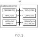
- FIG. 2 is an example of a block diagram of an electronic device according to an embodiment.
- An electronic device 101 of FIG. 2 may be an example of the electronic device 101 of FIG. 1 .
- a processor 120 of FIG. 2 may be an example of the processor 120 of FIG. 1 .
- Operations of FIG. 2 may be executed by the processor 120 of FIG. 1 and/or FIG. 2 .
- the electronic device 101 may have a form of glasses wearable to a body part (e.g., head) of a user.
- the electronic device 101 of FIG. 2 may include a head-mounted display (HMD).
- HMD head-mounted display
- a housing of the electronic device 101 may include a flexible material such as rubber and/or silicon having a shape in close contact with a portion (e.g., a portion of a face covering both eyes) of the user's head.
- the housing of the electronic device 101 may include one or more straps that may be able to be twined around the user's head, and/or one or more temples attachable to an ear of the head.
- the electronic device 101 may include at least one of a processor 120, a speaker 210, a microphone array 220, a display 230, a camera 240, or communication circuitry 250.
- the processor 120, the speaker 210, the microphone array 220, the display 230, the camera 240, and the communication circuitry 250 may be electronically and/or operably coupled with each other by an electronical component such as a communication bus 260.
- Hardware being operably coupled may mean that a direct connection or an indirect connection between the hardware is established wired or wirelessly so that certain hardware is controlled by other hardware among the hardware.
- a type and/or the number of hardware included in the electronic device 101 is not limited to an example of FIG. 2 .
- the processor 120 of the electronic device 101 may include a hardware component for processing data based on one or more instructions.
- the hardware component for processing data may include an arithmetic and logic unit (ALU), a floating point unit (FPU), a field programmable gate array (FPGA), and/or a central processing unit (CPU).
- the number of the processor 120 may be one or more.
- the processor 120 may have a structure of a multi-core processor such as a dual core, a quad core, or a hexa core.
- the processor 120 of FIG. 2 may include the processor 120 of FIG. 1 .
- an application being installed in the electronic device 101 may mean that one or more instructions provided in a form of the application are stored in the memory of the electronic device 101 and the application is stored in an executable format (e.g., a file with an extension preset by the operating system of the electronic device 101) by the processor 120 of the electronic device 101.
- an executable format e.g., a file with an extension preset by the operating system of the electronic device 101
- the display 230 may include a light source (e.g., backlight) for emitting light toward the LCD.
- the light source may be omitted in an embodiment where the display 230 includes the OLED.
- the display 230 may include a panel and at least one display driver integrated-circuit (DDI).
- the DDI may control at least one LED included in a corresponding row or column among the plurality of LEDs. That the DDI controls at least one LED may include adjusting luminance and/or brightness of the LEDs.
- the electronic device 101 may provide the user with a user experience associated with a virtual reality, using the display 230.
- a structure of the electronic device 101 to provide the user experience associated with the virtual reality will be described with reference to FIGS. 4A to 4B .
- the electronic device 101 may include other output means to output information in a different form other than a visual form and an audible form.
- the electronic device 101 may include a motor to provide haptic feedback based on vibration.
- a portion e.g., the processor 120, the speaker 210, the microphone array 220, the display 230, the camera 240, and the communication circuitry 250
- SoC system on a chip
- the electronic device 101 may identify the position of the external object based on a plurality of microphones arranged in the microphone array 220 of the electronic device 101.
- the electronic device 101 may control the microphone array 220 based on the identified position of the external object.
- the electronic device 101 may form a beam having an azimuth angle corresponding to the identified position by the microphone array 220.
- the electronic device 101 may obtain the acoustic signal generated by the external object, based on forming the beam.
- the electronic device may superimpose (or add), in response to the input for increasing the volume, a tuning signal having a phase corresponding to a phase of the acoustic signal on the acoustic signal.
- the electronic device 101 may change the superimposed (or added) acoustic signal into the audio signal and output a relatively loud sound compared to before receiving the input for increasing the volume.
- the electronic device 101 may output, in response to the input for decreasing the volume, an audio signal having a preset difference with respect to a phase of the acoustic signal.
- An operation of the electronic device 101 for decreasing the volume of the acoustic signal may be referred to as an active noise canceling (ANC) function.
- ANC active noise canceling
- the electronic device 101 may be connected to the external object (e.g., a TV or a speaker) through the communication circuitry 250.
- the electronic device 101 may display, in association with the external object viewable through the display 230, a visual object to control the external object.
- the visual object to control the external object may be a visual object to adjust the volume of the acoustic signal transmitted from the external object.
- the electronic device 101 may receive the input to adjust the volume of the acoustic signal transmitted from the external object through the visual object.
- the electronic device 101 may superimpose (or add), in response to the input for increasing the volume of the acoustic signal, a tuning signal having a phase corresponding to the acoustic signal transmitted from the external object on the acoustic signal.
- the electronic device 101 may obtain, based on the tuning signal superimposed on the acoustic signal, an audio signal.
- the electronic device 101 may output the audio signal through the speaker 210.
- the electronic device 101 may superimpose (or add), in response to the input for decreasing the volume of the acoustic signal, the tuning signal, which is corresponding to the acoustic signal transmitted from the external object, having a preset difference with respect to a phase of the acoustic signal, on the acoustic signal.
- the electronic device 101 may obtain, based on superimposing (or adding) the tuning signal on the acoustic signal, the audio signal.
- the electronic device 101 may output, based on obtaining the audio signal, the audio signal through the speaker 210.
- the electronic device 101 may display the visual object to adjust the volume of the external object while displaying the external object connected through the communication circuitry 250.
- the electronic device 101 may receive an input for the visual object.
- the electronic device 101 may receive an input to adjust the volume of the external object received based on the visual object.
- the electronic device 101 transmit, in response to the input, a control signal to adjust the volume of the audio signal outputted by the external object, to the external object through the communication circuitry 250.
- the external object may adjust the volume based on the control signal.
- FIG. 3A is an example of a perspective view of an electronic device according to an embodiment.
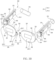
- FIG. 3B is an example of one or more hardware disposed in an electronic device according to an embodiment.
- An electronic device 101 of FIGS. 3A to 3B may be an example of the electronic device 101 of FIG. 1 to FIG 2 .
- the electronic device 101 may include at least one display 230 and a frame 300 supporting the at least one display 230.
- the at least one display 230 may be an example of the display 230 of FIG. 2 .
- the electronic device 101 may be wearable on a portion of the user's body.
- the electronic device 101 may provide augmented reality (AR), virtual reality (VR), or mixed reality (MR) combining the augmented reality and the virtual reality to a user wearing the electronic device 101.
- AR augmented reality
- VR virtual reality
- MR mixed reality
- the electronic device 101 may display a virtual reality image provided from at least one optical device 382 and 384 of FIG. 3B on at least one display 230, in response to a user's preset gesture obtained through a motion recognition camera 240-2 and 364 of FIG. 3B .
- the at least one display 230 may provide visual information transmitted through a lens included in the at least one display 230 from ambient light to a user and other visual information distinguished from the visual information.
- the lens may be formed based on at least one of a fresnel lens, a pancake lens, or a multi-channel lens.
- the at least one display 230 may include a first surface 331 and a second surface 332 opposite to the first surface 331.
- a display area may be formed on the second surface 332 of at least one display 230.
- ambient light may be transmitted to the user by being incident on the first surface 331 and being penetrated through the second surface 332.
- the at least one display 230 may display an augmented reality image in which a virtual reality image provided by the at least one optical device 382 and 384 is combined with a reality screen transmitted through ambient light, on a display area formed on the second surface 332.
- the at least one display 230 may include at least one waveguide 333 and 334 that transmits light transmitted from the at least one optical device 382 and 384 by diffracting to the user.
- the at least one waveguide 333 and 334 may be formed based on at least one of glass, plastic, or polymer.
- a nano pattern may be formed on at least a portion of the outside or inside of the at least one waveguide 333 and 334.
- the nano pattern may be formed based on a grating structure having a polygonal or curved shape. Light incident to an end of the at least one waveguide 333 and 334 may be propagated to another end of the at least one waveguide 333 and 334 by the nano pattern.
- the at least one waveguide 333 and 334 may include at least one of at least one diffraction element (e.g., a diffractive optical element (DOE), a holographic optical element (HOE)), and a reflection element (e.g., a reflection mirror).
- the at least one waveguide 333 and 334 may be disposed in the electronic device 101 to guide a screen displayed by the at least one display 230 to the user's eyes.
- the screen may be transmitted to the user's eyes based on total internal reflection (TIR) generated in the at least one waveguide 333 and 334.
- TIR total internal reflection
- the electronic device 101 may analyze an object included in a real image collected through a photographing camera (not illustrated) (e.g., the camera 240 of FIG. 2 ), combine with a virtual object corresponding to an object that become a subject of augmented reality provision among the analyzed object, and display on the at least one display 230.
- the virtual object may include at least one of text and images for various information associated with the object included in the real image.
- the electronic device 101 may analyze the object based on a multi-camera such as a stereo camera. For the object analysis, the electronic device 101 may execute time-of-flight (ToF) and/or simultaneous localization and mapping (SLAM), which are supported by the multi-camera.
- the user wearing the electronic device 101 may watch an image displayed on the at least one display 230.
- a frame 300 may be configured with a physical structure in which the electronic device 101 may be worn on the user's body. According to an embodiment, the frame 300 may be configured so that when the user wears the electronic device 101, the first display 230-1 and the second display 230-2 may be positioned corresponding to the user's left and right eyes.
- the frame 300 may support the at least one display 230.
- the frame 300 may support the first display 230-1 and the second display 230-2 to be positioned at positions corresponding to the user's left and right eyes.
- the frame 300 may include an area 320 at least partially in contact with the portion of the user's body in case that the user wears the electronic device 101.
- the area 320 of the frame 300 in contact with the portion of the user's body may include an area in contact with a portion of the user's nose, a portion of the user's ear, and a portion of the side of the user's face that the electronic device 101 contacts.
- the frame 300 may include a nose pad 310 that is contacted on the portion of the user's body. When the electronic device 101 is worn by the user, the nose pad 310 may be contacted on the portion of the user's nose.
- the frame 300 may include a first temple 304 and a second temple 305, which are contacted on another portion of the user's body that is distinct from the portion of the user's body.
- the frame 300 may include a first rim 301 surrounding at least a portion of the first display 230-1, a second rim 302 surrounding at least a portion of the second display 230-2, a bridge 303 disposed between the first rim 301 and the second rim 302, a first pad 311 disposed along a portion of the edge of the first rim 301 from one end of the bridge 303, a second pad 312 disposed along a portion of the edge of the second rim 302 from the other end of the bridge 303, the first temple 304 extending from the first rim 301 and fixed to a portion of the wearer's ear, and the second temple 305 extending from the second rim 302 and fixed to a portion of the ear opposite to the ear.
- the electronic device 101 may include hardware (e.g., hardware described above based on the block diagram of FIG. 2 ) that performs various functions.
- the hardware may include a battery module 370, an antenna module 375, the at least one optical device 382 and 384, a speaker 210, a microphone array 220, a light emitting module (not illustrated), and/or a printed circuit board 390.
- Various hardware may be disposed in the frame 300.
- the at least one optical device 382 and 384 may project a virtual object on the at least one display 230 to provide various image information to a user.
- the at least one optical device 382 and 384 may be projectors.
- the at least one optical device 382 and 384 may be disposed adjacent to the at least one display 230 or may be included in the at least one display 230 as a portion of the at least one display 230.
- the electronic device 101 may include a first optical device 382 corresponding to the first display 230-1 and a second optical device 384 corresponding to the second display 230-2.
- a camera 240 may include the photographing camera, an eye tracking camera (ET CAM) 240-1, and/or the motion recognition camera 240-2 and 364.
- the photographing camera, the eye tracking camera 240-1, and the motion recognition camera 240-2 and 364 may be disposed at different positions on the frame 300 and may perform different functions.
- the eye tracking camera 240-1 may output data indicating a gaze of the user wearing the electronic device 101.
- the electronic device 101 may detect the gaze from an image including the user's pupil obtained through the eye tracking camera 240-1.
- An example in which the eye tracking camera 240-1 is disposed toward the user's right eye is illustrated in FIG. 3B , but the embodiment is not limited thereto, and the eye tracking camera 240-1 may be disposed alone toward the user's left eye or may be disposed toward two eyes.
- FIGS. 4A to 4B are an example of an external appearance of an electronic device according to an embodiment.
- An electronic device 101 of FIGS. 4A to 4B may be an example of the electronic device 101 of FIG. 2 .
- an example of an external appearance of a first surface 410 of a housing of the electronic device 101 may be illustrated in FIG. 4A
- an example of an external appearance of a second surface 420 opposite to the first surface 410 may be illustrated in FIG. 4B .
- the electronic device 101 may identify the second external object 520.
- the electronic device 101 may identify a direction of the second external object 520.
- the electronic device 101 may identify a direction from the electronic device 101 to the second external object 520.
- the electronic device 101 may identify a position of the second external object 520.
- the electronic device 101 may identify the position of the second external object 520 in an image.
- the electronic device 101 may output, based on increasing the volume of the acoustic signal of the virtual object 530, an audio signal associated with the acoustic signal through the speaker.
- the electronic device 101 may receive, based on the second visual object 533 such as the slider, an input for decreasing the volume of the acoustic signal of the virtual object 530.
- the electronic device 101 may decrease, based on the input for decreasing the volume of the acoustic signal, the volume of the acoustic signal of the virtual object 530.
- the electronic device 101 may output, based on decreasing the volume of the acoustic signal of the virtual object 530, the audio signal associated with the acoustic signal through the speaker.
- the electronic device 101 may identify the first external object 510.
- the electronic device 101 may identify the second external object 520 connected through the communication circuitry.
- the electronic device 101 may identify the virtual object 530.
- the electronic device 101 may display, based on identifying the first external object 510, the bounding box 511 including the first external object 510.
- the electronic device 101 may display, based on identifying the second external object 520, the bounding box 521 including the second external object 520.
- the electronic device 101 may display, based on identifying the virtual object 530, the bounding box 531 including the virtual object 530.
- amplitude of the tuning signal 620 may vary according to the input for increasing the volume of the acoustic signal 610.
- the amplitude of the tuning signal 620 may be matched to a distance moved by the visual object such as the slider of FIGS. 5B to 5C .
- the electronic device may superimpose the tuning signal 620 on the acoustic signal 610, based on the input for increasing the volume of the acoustic signal 610.
- the electronic device 101 may obtain an audio signal 630, based on superimposing the tuning signal 620 on the acoustic signal 610.
- the audio signal may include an electrical signal to output through a speaker.
- the electronic device may output, in response to obtaining the audio signal 630, the audio signal 630 through the speaker.
- the electronic device may identify a direction from the electronic device to the external object.
- the electronic device may control, based on the direction, a microphone array.
- the electronic device may obtain, by controlling the microphone array, an acoustic signal corresponding to the direction.
- the electronic device may obtain, by controlling the microphone array, an acoustic signal generated by the external object.
- the electronic device may form a beam having an azimuth angle corresponding to the identified position.
- the electronic device may obtain, based on the formed beam, the acoustic signal.
- the electronic device may output, in response to an input to adjust the volume received based on the visual object, an audio associated with the acoustic signal through a speaker (e.g., the speaker 210 of FIG. 2 ).
- a speaker e.g., the speaker 210 of FIG. 2
- the electronic device may superimpose a tuning signal corresponding to the acoustic signal on the acoustic signal, in response to an input for increasing the volume of the acoustic signal.
- the electronic device may obtain an audio signal, based on superimposing of the acoustic signal and the tuning signal.
- the electronic device may output the audio signal obtained based on the acoustic signal and the tuning signal through the speaker.
- the electronic device may receive the input to adjust the volume of the acoustic signal, based on the visual object such as the slider. For example, the electronic device may receive the input for increasing the volume of the acoustic signal. The electronic device may obtain, in response to the input for increasing the volume the acoustic signal, the audio signal having a phase corresponding to a phase of the acoustic signal. For example, the audio signal may include a signal superimposed with the tuning signal having a phase corresponding to the acoustic signal.
- the electronic device may receive the input for decreasing the volume of the acoustic signal.
- the electronic device may obtain an audio signal, which is corresponding to the acoustic signal, having the preset difference with respect to the phase of the acoustic signal.
- the audio signal may be obtained based on a tuning signal, which is corresponding to the acoustic signal, having the phase of a preset difference (about 180°) with respect to the phase of the acoustic signal.
- the electronic device may superimpose the acoustic signal and the tuning signal, which is corresponding to the acoustic signal, having the phase of the preset difference with respect to the phase of the acoustic signal.
- the electronic device may obtain the audio signal, based on superimposing the acoustic signal and the tuning signal.
- the electronic device in response to the input for decreasing the volume of the acoustic signal, the electronic device may superimpose the tuning signal, which is corresponding to the acoustic signal, having the preset difference with respect to the phase of the acoustic signal on the acoustic signal.
- the electronic device may obtain the audio signal based on superimposing of the acoustic signal and the tuning signal.
- the electronic device may output the audio signal obtained based on superimposing of the acoustic signal and the tuning signal through the speaker.
- the electronic device may obtain the acoustic signal generated by the external object.
- the electronic device may generate, based on obtaining the acoustic signal, the tuning signal to adjust the volume of the acoustic signal.
- the electronic device may superimpose the acoustic signal and the tuning signal.
- the electronic device may obtain the audio signal based on superimposing of the acoustic signal and the tuning signal.
- the electronic device may output the audio signal through the speaker.
- the electronic device may enhance a user experience of the electronic device by outputting the audio signal.
- an electronic device 101 may comprise a display 230, a camera 240, a speaker 210, a microphone array 220 including a plurality of microphones, and a processor 120.
- the processor 120 may identify, based on an image obtained by the camera 240, an external object 510 viewable through the display 230.
- the processor 120 may obtain, by controlling the microphone array 220 based on a direction of the identified external object, an acoustic signal corresponding to the direction.
- the processor 120 may display, based on the acoustic signal, a visual object to adjust a volume of the acoustic signal in the display 230 based on a position of the external object identified in the image.
- the processor 120 may output, in response to an input to adjust the volume received based on the visual object, an audio signal associated with the acoustic signal through the speaker 210.
- the processor 120 may obtain, based on a beam having an azimuth angle corresponding to the identified position and formed by the microphone array 220, the acoustic signal.
- the electronic device 101 may comprise communication circuitry 250.
- the processor 120 may, in a state connected with a second external object 520 through the communication circuitry 250 that is different from the external object 510 which is a first external object 510, display, in association with the second external object 520 viewable through the display 230, a second visual object to control the second external object 520 that is different from the visual object which is a first visual object.
- the processor 120 may transmit, in response to an input to adjust a volume of the second external object 520 received based on the second visual object, a control signal to adjust a volume of another audio signal outputted by the second external object 520, to the second external object 520 through the communication circuitry 250.
- the processor 120 may display the visual object superimposed on at least a portion of an area where the external object 510 is identified.
- the method of the electronic device 101 may comprise transmitting, in response to an input to adjust a volume of the second external object 520 received based on the second visual object, a signal to adjust a volume of another audio signal outputted by the second external object 520, to the second external object 520 through the communication circuitry 250.
- a computer-readable storage medium storing one or more programs, wherein the one or more programs, when executed by a processor 120 of an electronic device 101, may cause the processor 120 of the electronic device 101 to identify, based on an image obtained by a camera 240, an external object 510 viewable through a display 230.
- the one or more programs when executed by the processor 120 of the electronic device 101, may cause the processor 120 of the electronic device 101 to obtain, by controlling a microphone array 220 based on a direction of the identified external object, an acoustic signal corresponding to the direction.
- the one or more programs when executed by the processor 120 of the electronic device 101, may cause the processor 120 of the electronic device 101 to obtain, based on a beam having an azimuth angle corresponding to the identified position and formed by the microphone array 220, the acoustic signal.
- the one or more programs when executed by the processor 120 of the electronic device 101, may cause the processor 120 of the electronic device 101 to transmit, in response to an input to adjust a volume of the second external object 520 received based on the second visual object, a signal to adjust a volume of another audio signal outputted by the second external object 520, to the second external object 520 through the communication circuitry 250.
- the one or more programs when executed by the processor 120 of the electronic device 101, may cause the processor 120 of the electronic device 101 to display the visual object superimposed on at least a portion of an area where the external object 510 is identified.
- the one or more programs when executed by the processor 120 of the electronic device 101, may cause the processor 120 of the electronic device 101 to display the second visual object superimposed on at least a portion of an area where the second external object 520 is identified.
- the one or more programs when executed by the processor 120 of the electronic device 101, may cause the processor 120 of the electronic device 101 to output, in response to the input for increasing the volume, the audio signal having a phase corresponding to a phase of the acoustic signal.
- the one or more programs when executed by the processor 120 of the electronic device 101, may cause the processor 120 of the electronic device 101 to output, in response to the input for decreasing the volume, the audio signal, which is corresponding to the acoustic signal, having a preset difference with respect to a phase of the acoustic signal.
- the electronic device may be one of various types of electronic devices.
- the electronic devices may include, for example, a portable communication device (e.g., a smartphone), a computer device, a portable multimedia device, a portable medical device, a camera, a wearable device, or a home appliance. According to an embodiment of the disclosure, the electronic devices are not limited to those described above.
- each of such phrases as “A or B,” “at least one of A and B,” “at least one of A or B,” “A, B, or C,” “at least one of A, B, and C,” and “at least one of A, B, or C,” may include any one of or all possible combinations of the items enumerated together in a corresponding one of the phrases.
- such terms as “1st” and “2nd,” or “first” and “second” may be used to simply distinguish a corresponding component from another, and does not limit the components in other aspect (e.g., importance or order).
- an element e.g., a first element
- operatively or “communicatively”, as “coupled with,” or “connected with” another element
- the element may be coupled with the other element directly (e.g., wiredly), wirelessly, or via a third element.
- module may include a unit implemented in hardware, software, or firmware, and may interchangeably be used with other terms, for example, “logic,” “logic block,” “part,” or “circuitry”.
- a module may be a single integral component, or a minimum unit or part thereof, adapted to perform one or more functions.
- the module may be implemented in a form of an application-specific integrated circuit (ASIC).
- ASIC application-specific integrated circuit
- the machine-readable storage medium may be provided in the form of a non-transitory storage medium.
- non-transitory simply means that the storage medium is a tangible device, and does not include a signal (e.g., an electromagnetic wave), but this term does not differentiate between a case in which data is semi-permanently stored in the storage medium and a case in which the data is temporarily stored in the storage medium.
- a method may be included and provided in a computer program product.
- the computer program product may be traded as a product between a seller and a buyer.
- the computer program product may be distributed in the form of a machine-readable storage medium (e.g., compact disc read only memory (CD-ROM)), or be distributed (e.g., downloaded or uploaded) online via an application store (e.g., PlayStore TM ), or between two user devices (e.g., smart phones) directly. If distributed online, at least part of the computer program product may be temporarily generated or at least temporarily stored in the machine-readable storage medium, such as memory of the manufacturer's server, a server of the application store, or a relay server.
- CD-ROM compact disc read only memory
- an application store e.g., PlayStore TM
- two user devices e.g., smart phones
- each component e.g., a module or a program of the above-described components may include a single entity or multiple entities, and some of the multiple entities may be separately disposed in different components. According to various embodiments, one or more of the above-described components may be omitted, or one or more other components may be added. Alternatively or additionally, a plurality of components (e.g., modules or programs) may be integrated into a single component. In such a case, according to various embodiments, the integrated component may still perform one or more functions of each of the plurality of components in the same or similar manner as they are performed by a corresponding one of the plurality of components before the integration.
- operations performed by the module, the program, or another component may be carried out sequentially, in parallel, repeatedly, or heuristically, or one or more of the operations may be executed in a different order or omitted, or one or more other operations may be added.
Landscapes
- Engineering & Computer Science (AREA)
- Theoretical Computer Science (AREA)
- Physics & Mathematics (AREA)
- General Engineering & Computer Science (AREA)
- Human Computer Interaction (AREA)
- General Physics & Mathematics (AREA)
- Health & Medical Sciences (AREA)
- Signal Processing (AREA)
- General Health & Medical Sciences (AREA)
- Acoustics & Sound (AREA)
- Otolaryngology (AREA)
- Audiology, Speech & Language Pathology (AREA)
- Multimedia (AREA)
- Computer Networks & Wireless Communication (AREA)
- Computer Hardware Design (AREA)
- Environmental & Geological Engineering (AREA)
- User Interface Of Digital Computer (AREA)
- Telephone Function (AREA)
Applications Claiming Priority (3)
| Application Number | Priority Date | Filing Date | Title |
|---|---|---|---|
| KR20220120865 | 2022-09-23 | ||
| KR1020220141919A KR20240041775A (ko) | 2022-09-23 | 2022-10-28 | 디스플레이를 통해 보여지는 객체와 관련된 오디오 신호를 조절하기 위한 전자 장치 및 그 방법 |
| PCT/KR2023/013998 WO2024063463A1 (ko) | 2022-09-23 | 2023-09-15 | 디스플레이를 통해 보여지는 객체와 관련된 오디오 신호를 조절하기 위한 전자 장치 및 그 방법 |
Publications (2)
| Publication Number | Publication Date |
|---|---|
| EP4579433A1 true EP4579433A1 (de) | 2025-07-02 |
| EP4579433A4 EP4579433A4 (de) | 2025-11-12 |
Family
ID=90454891
Family Applications (1)
| Application Number | Title | Priority Date | Filing Date |
|---|---|---|---|
| EP23868515.0A Pending EP4579433A4 (de) | 2022-09-23 | 2023-09-15 | Elektronische vorrichtung zur einstellung eines audiosignals im zusammenhang mit einem durch eine anzeige angezeigten objekt und verfahren dafür |
Country Status (3)
| Country | Link |
|---|---|
| US (1) | US20250224916A1 (de) |
| EP (1) | EP4579433A4 (de) |
| WO (1) | WO2024063463A1 (de) |
Family Cites Families (7)
| Publication number | Priority date | Publication date | Assignee | Title |
|---|---|---|---|---|
| JP2012133250A (ja) * | 2010-12-24 | 2012-07-12 | Sony Corp | 音情報表示装置、音情報表示方法およびプログラム |
| JP6065370B2 (ja) * | 2012-02-03 | 2017-01-25 | ソニー株式会社 | 情報処理装置、情報処理方法、及びプログラム |
| US20170277257A1 (en) * | 2016-03-23 | 2017-09-28 | Jeffrey Ota | Gaze-based sound selection |
| KR20190101329A (ko) * | 2019-08-12 | 2019-08-30 | 엘지전자 주식회사 | 지능적 음성 출력 방법, 음성 출력 장치 및 지능형 컴퓨팅 디바이스 |
| EP3963902A4 (de) * | 2019-09-24 | 2022-07-13 | Samsung Electronics Co., Ltd. | Verfahren und systeme zur aufzeichnung von gemischten audiosignalen und wiedergabe von gerichteten audiosignalen |
| KR20210070634A (ko) * | 2019-12-05 | 2021-06-15 | 엘지전자 주식회사 | 인공 지능 장치 및 그의 동작 방법 |
| KR102863021B1 (ko) * | 2020-11-13 | 2025-09-22 | 삼성전자주식회사 | 전자장치 및 그 제어방법 |
-
2023
- 2023-09-15 WO PCT/KR2023/013998 patent/WO2024063463A1/ko not_active Ceased
- 2023-09-15 EP EP23868515.0A patent/EP4579433A4/de active Pending
-
2025
- 2025-03-21 US US19/087,023 patent/US20250224916A1/en active Pending
Also Published As
| Publication number | Publication date |
|---|---|
| US20250224916A1 (en) | 2025-07-10 |
| WO2024063463A1 (ko) | 2024-03-28 |
| EP4579433A4 (de) | 2025-11-12 |
Similar Documents
| Publication | Publication Date | Title |
|---|---|---|
| US20250085771A1 (en) | Device, method, and storage medium for performing tracking using external electronic device | |
| EP4517514A1 (de) | Elektronische vorrichtung zur lautstärkeeinstellung unter verwendung eines aus einem externen objekt ausgegebenen tonsignals und verfahren dafür | |
| KR20240041775A (ko) | 디스플레이를 통해 보여지는 객체와 관련된 오디오 신호를 조절하기 위한 전자 장치 및 그 방법 | |
| EP4579433A1 (de) | Elektronische vorrichtung zur einstellung eines audiosignals im zusammenhang mit einem durch eine anzeige angezeigten objekt und verfahren dafür | |
| KR20240050198A (ko) | 사용자의 자세를 가이드하기 위한 웨어러블 장치 및 그 방법 | |
| US20240107251A1 (en) | Electronic device for changing audio signal based on information related to visual object and method thereof | |
| US12260142B2 (en) | Electronic device and method for controlling display of at least one external object among one or more external objects | |
| US12394069B2 (en) | Electronic device, method, and storage medium for obtaining image for tracking | |
| US20250173919A1 (en) | Device and method for measuring distance with respect to external object | |
| EP4546090A1 (de) | Elektronische vorrichtung zur auswahl von mindestens einer externen elektronischen vorrichtung auf basis von mindestens einem externen objekt und verfahren dafür | |
| US12456164B2 (en) | Electronic device for controlling resolution of each of plurality of areas included in image acquired from camera and method thereof | |
| US20260037206A1 (en) | Electronic device, method, and non-transitory computer readable storage medium for interacting with wearable device | |
| EP4579397A1 (de) | Wearable-vorrichtung, verfahren und computerlesbares speichermedium zur anpassung von blickinformationen eines benutzers | |
| US12061344B2 (en) | Electronic device for controlling wearable device based on input of electronic device and method thereof | |
| US20260072277A1 (en) | Wearable device, method, and non-transitory computer-readable storage medium for displaying screen based on visual acuity of user | |
| US20260003437A1 (en) | Electronic device and method for providing function related to extended reality | |
| EP4579398A1 (de) | Tragbare vorrichtung zur führung der haltung eines benutzers und verfahren dafür | |
| US12444111B2 (en) | Electronic device and method for providing notification information based on gaze of user | |
| US20260127833A1 (en) | Electronic device and method for tracking external object in virtual environment | |
| US20260099202A1 (en) | Electronic device and method for adjusting order of data sets for controlling led, and computer-readable storage medium | |
| KR20240041779A (ko) | 시각적 객체와 관련된 정보에 기반하여 오디오 신호를 변경하는 전자 장치 및 그 방법 | |
| KR20250011553A (ko) | 객체 인식에 기반하여 시각적 객체를 표시하기 위한 전자 장치 및 방법 | |
| KR20240014991A (ko) | 외부 객체로부터 출력된 소리 신호를 이용하여 볼륨을 조절하기 위한 전자 장치 및 그 방법 | |
| EP4722867A1 (de) | Elektronische vorrichtung, verfahren und nichttransitorisches computerlesbares speichermedium zum erhalt einer benachrichtigung aus einem fahrzeug | |
| KR20250030878A (ko) | 추적을 위한 이미지를 획득하기 위한 전자 장치, 방법, 및 저장 매체 |
Legal Events
| Date | Code | Title | Description |
|---|---|---|---|
| STAA | Information on the status of an ep patent application or granted ep patent |
Free format text: STATUS: THE INTERNATIONAL PUBLICATION HAS BEEN MADE |
|
| PUAI | Public reference made under article 153(3) epc to a published international application that has entered the european phase |
Free format text: ORIGINAL CODE: 0009012 |
|
| STAA | Information on the status of an ep patent application or granted ep patent |
Free format text: STATUS: REQUEST FOR EXAMINATION WAS MADE |
|
| 17P | Request for examination filed |
Effective date: 20250324 |
|
| AK | Designated contracting states |
Kind code of ref document: A1 Designated state(s): AL AT BE BG CH CY CZ DE DK EE ES FI FR GB GR HR HU IE IS IT LI LT LU LV MC ME MK MT NL NO PL PT RO RS SE SI SK SM TR |
|
| A4 | Supplementary search report drawn up and despatched |
Effective date: 20251014 |
|
| RIC1 | Information provided on ipc code assigned before grant |
Ipc: G06F 3/16 20060101AFI20251008BHEP Ipc: G06F 3/04842 20220101ALI20251008BHEP Ipc: G06F 3/04847 20220101ALI20251008BHEP Ipc: G06F 3/04817 20220101ALI20251008BHEP Ipc: G06F 3/0482 20130101ALI20251008BHEP Ipc: H04W 4/80 20180101ALI20251008BHEP Ipc: G06F 3/00 20060101ALI20251008BHEP Ipc: G06F 3/01 20060101ALI20251008BHEP Ipc: H04M 1/72415 20210101ALI20251008BHEP |
|
| DAV | Request for validation of the european patent (deleted) | ||
| DAX | Request for extension of the european patent (deleted) | ||
| STAA | Information on the status of an ep patent application or granted ep patent |
Free format text: STATUS: EXAMINATION IS IN PROGRESS |