EP4579397A1 - Wearable-vorrichtung, verfahren und computerlesbares speichermedium zur anpassung von blickinformationen eines benutzers - Google Patents
Wearable-vorrichtung, verfahren und computerlesbares speichermedium zur anpassung von blickinformationen eines benutzers Download PDFInfo
- Publication number
- EP4579397A1 EP4579397A1 EP23875078.0A EP23875078A EP4579397A1 EP 4579397 A1 EP4579397 A1 EP 4579397A1 EP 23875078 A EP23875078 A EP 23875078A EP 4579397 A1 EP4579397 A1 EP 4579397A1
- Authority
- EP
- European Patent Office
- Prior art keywords
- wearable device
- user
- visual object
- camera
- information
- Prior art date
- Legal status (The legal status is an assumption and is not a legal conclusion. Google has not performed a legal analysis and makes no representation as to the accuracy of the status listed.)
- Pending
Links
Images


Classifications
-
- G—PHYSICS
- G06—COMPUTING OR CALCULATING; COUNTING
- G06F—ELECTRIC DIGITAL DATA PROCESSING
- G06F1/00—Details not covered by groups G06F3/00 - G06F13/00 and G06F21/00
- G06F1/16—Constructional details or arrangements
- G06F1/1613—Constructional details or arrangements for portable computers
- G06F1/163—Wearable computers, e.g. on a belt
-
- G—PHYSICS
- G02—OPTICS
- G02B—OPTICAL ELEMENTS, SYSTEMS OR APPARATUS
- G02B27/00—Optical systems or apparatus not provided for by any of the groups G02B1/00 - G02B26/00, G02B30/00
- G02B27/01—Head-up displays
- G02B27/017—Head mounted
- G02B27/0172—Head mounted characterised by optical features
-
- G—PHYSICS
- G06—COMPUTING OR CALCULATING; COUNTING
- G06F—ELECTRIC DIGITAL DATA PROCESSING
- G06F1/00—Details not covered by groups G06F3/00 - G06F13/00 and G06F21/00
- G06F1/16—Constructional details or arrangements
- G06F1/1613—Constructional details or arrangements for portable computers
- G06F1/1633—Constructional details or arrangements of portable computers not specific to the type of enclosures covered by groups G06F1/1615 - G06F1/1626
- G06F1/1656—Details related to functional adaptations of the enclosure, e.g. to provide protection against EMI, shock, water, or to host detachable peripherals like a mouse or removable expansions units like PCMCIA cards, or to provide access to internal components for maintenance or to removable storage supports like CDs or DVDs, or to mechanically mount accessories
- G06F1/1658—Details related to functional adaptations of the enclosure, e.g. to provide protection against EMI, shock, water, or to host detachable peripherals like a mouse or removable expansions units like PCMCIA cards, or to provide access to internal components for maintenance or to removable storage supports like CDs or DVDs, or to mechanically mount accessories related to the mounting of internal components, e.g. disc drive or any other functional module
-
- G—PHYSICS
- G06—COMPUTING OR CALCULATING; COUNTING
- G06F—ELECTRIC DIGITAL DATA PROCESSING
- G06F1/00—Details not covered by groups G06F3/00 - G06F13/00 and G06F21/00
- G06F1/16—Constructional details or arrangements
- G06F1/1613—Constructional details or arrangements for portable computers
- G06F1/1633—Constructional details or arrangements of portable computers not specific to the type of enclosures covered by groups G06F1/1615 - G06F1/1626
- G06F1/1684—Constructional details or arrangements related to integrated I/O peripherals not covered by groups G06F1/1635 - G06F1/1675
- G06F1/1686—Constructional details or arrangements related to integrated I/O peripherals not covered by groups G06F1/1635 - G06F1/1675 the I/O peripheral being an integrated camera
-
- G—PHYSICS
- G06—COMPUTING OR CALCULATING; COUNTING
- G06F—ELECTRIC DIGITAL DATA PROCESSING
- G06F3/00—Input arrangements for transferring data to be processed into a form capable of being handled by the computer; Output arrangements for transferring data from processing unit to output unit, e.g. interface arrangements
- G06F3/01—Input arrangements or combined input and output arrangements for interaction between user and computer
- G06F3/011—Arrangements for interaction with the human body, e.g. for user immersion in virtual reality
- G06F3/013—Eye tracking input arrangements
-
- G—PHYSICS
- G06—COMPUTING OR CALCULATING; COUNTING
- G06F—ELECTRIC DIGITAL DATA PROCESSING
- G06F3/00—Input arrangements for transferring data to be processed into a form capable of being handled by the computer; Output arrangements for transferring data from processing unit to output unit, e.g. interface arrangements
- G06F3/01—Input arrangements or combined input and output arrangements for interaction between user and computer
- G06F3/017—Gesture based interaction, e.g. based on a set of recognized hand gestures
-
- G—PHYSICS
- G06—COMPUTING OR CALCULATING; COUNTING
- G06F—ELECTRIC DIGITAL DATA PROCESSING
- G06F3/00—Input arrangements for transferring data to be processed into a form capable of being handled by the computer; Output arrangements for transferring data from processing unit to output unit, e.g. interface arrangements
- G06F3/01—Input arrangements or combined input and output arrangements for interaction between user and computer
- G06F3/03—Arrangements for converting the position or the displacement of a member into a coded form
- G06F3/0304—Detection arrangements using opto-electronic means
-
- G—PHYSICS
- G06—COMPUTING OR CALCULATING; COUNTING
- G06F—ELECTRIC DIGITAL DATA PROCESSING
- G06F3/00—Input arrangements for transferring data to be processed into a form capable of being handled by the computer; Output arrangements for transferring data from processing unit to output unit, e.g. interface arrangements
- G06F3/01—Input arrangements or combined input and output arrangements for interaction between user and computer
- G06F3/048—Interaction techniques based on graphical user interfaces [GUI]
- G06F3/0481—Interaction techniques based on graphical user interfaces [GUI] based on specific properties of the displayed interaction object or a metaphor-based environment, e.g. interaction with desktop elements like windows or icons, or assisted by a cursor's changing behaviour or appearance
- G06F3/0482—Interaction with lists of selectable items, e.g. menus
-
- G—PHYSICS
- G06—COMPUTING OR CALCULATING; COUNTING
- G06F—ELECTRIC DIGITAL DATA PROCESSING
- G06F3/00—Input arrangements for transferring data to be processed into a form capable of being handled by the computer; Output arrangements for transferring data from processing unit to output unit, e.g. interface arrangements
- G06F3/01—Input arrangements or combined input and output arrangements for interaction between user and computer
- G06F3/048—Interaction techniques based on graphical user interfaces [GUI]
- G06F3/0484—Interaction techniques based on graphical user interfaces [GUI] for the control of specific functions or operations, e.g. selecting or manipulating an object, an image or a displayed text element, setting a parameter value or selecting a range
-
- G—PHYSICS
- G06—COMPUTING OR CALCULATING; COUNTING
- G06F—ELECTRIC DIGITAL DATA PROCESSING
- G06F3/00—Input arrangements for transferring data to be processed into a form capable of being handled by the computer; Output arrangements for transferring data from processing unit to output unit, e.g. interface arrangements
- G06F3/01—Input arrangements or combined input and output arrangements for interaction between user and computer
- G06F3/048—Interaction techniques based on graphical user interfaces [GUI]
- G06F3/0487—Interaction techniques based on graphical user interfaces [GUI] using specific features provided by the input device, e.g. functions controlled by the rotation of a mouse with dual sensing arrangements, or of the nature of the input device, e.g. tap gestures based on pressure sensed by a digitiser
-
- G—PHYSICS
- G06—COMPUTING OR CALCULATING; COUNTING
- G06V—IMAGE OR VIDEO RECOGNITION OR UNDERSTANDING
- G06V20/00—Scenes; Scene-specific elements
- G06V20/20—Scenes; Scene-specific elements in augmented reality scenes
-
- G—PHYSICS
- G06—COMPUTING OR CALCULATING; COUNTING
- G06V—IMAGE OR VIDEO RECOGNITION OR UNDERSTANDING
- G06V40/00—Recognition of biometric, human-related or animal-related patterns in image or video data
- G06V40/10—Human or animal bodies, e.g. vehicle occupants or pedestrians; Body parts, e.g. hands
- G06V40/18—Eye characteristics, e.g. of the iris
-
- G—PHYSICS
- G06—COMPUTING OR CALCULATING; COUNTING
- G06V—IMAGE OR VIDEO RECOGNITION OR UNDERSTANDING
- G06V40/00—Recognition of biometric, human-related or animal-related patterns in image or video data
- G06V40/20—Movements or behaviour, e.g. gesture recognition
Definitions
- Various embodiments relate to a wearable device, a method, and a computer-readable storage medium for adjusting gaze information of a user.
- the wearable device may be operated by being worn on a part of a body of a user.
- the wearable device may display a visual object within a field-of-view (FoV), using a display.
- the wearable device may identify information indicating a direction of eyes of the user using a camera for identifying the eyes of the user.
- the wearable device may identify an external object that interacts with the visual object, using another camera for identifying an external environment.
- the wearable device may identify an interaction between the visual object and/or the external object.
- a wearable device may comprise a first camera, a second camera, a display and a processor.
- the processor may display, using the display, a visual object within a field of view (FoV) of a user, in a state where the wearable device is worn by the user.
- the processor may, while displaying the visual object, based on the first camera disposed toward the FoV, identify an external object, interacting with the visual object, seen through the FoV.
- the processor may obtain a position of the external object, based on identifying an interaction between the external object and the visual object using the first camera.
- FoV field of view
- the processor may be configured to change information indicating a direction of eyes identified by frames outputted from the second camera disposed toward the eyes of the user, using at least one of a position of the visual object or the position of the external object, based on obtaining the position of the external object.
- the method may comprise displaying, using a display, a visual object within a field of view (FoV) of a user, in a state where the wearable device is worn by the user.
- the method may comprise, while displaying the visual object, based on a first camera disposed toward the FoV, identifying an external object, interacting with the visual object, seen through the FoV.
- the method may comprise obtaining a position of the external object, based on identifying an interaction between the external object and the visual object using the first camera.
- the method may comprise changing information indicating a direction of eyes identified by frames outputted from a second camera disposed toward the eyes of the user, using at least one of a position of the visual object or the position of the external object, based on obtaining the position of the external object.
- the one or more programs may, when executed by a processor of a wearable device, display, using the display, a visual object within a FoV of a user, in a state where the wearable device is worn by the user.
- the one or more programs may, when executed by the processor, while displaying the visual object, based on the first camera disposed toward the FoV, identify an external object, interacting with the visual object, seen through the FoV.
- the one or more programs, when executed by the processor may obtain a position of the external object, based on identifying an interaction between the external object and the visual object using the first camera.
- the one or more programs when executed by the processor, may change information indicating a direction of eyes identified by frames outputted from the second camera disposed toward the eyes of the user, using at least one of a position of the visual object or the position of the external object, based on obtaining the position of the external object.
- Expressions such as “1st”, “2nd”, “first” or “second”, and the like may modify the corresponding components regardless of order or importance, is only used to distinguish one component from another component, but does not limit the corresponding components.
- a (e.g., first) component is referred to as “connected (functionally or communicatively)” or “accessed” to another (e.g., second) component, the component may be directly connected to the other component or may be connected through another component (e.g., a third component).
- module used in the present document may include a unit configured with hardware, software, or firmware, and may be used interchangeably with terms such as logic, logic block, component, or circuit, and the like.
- the module may be an integrally configured component or a minimum unit or part thereof that performs one or more functions.
- a module may be configured with an application-specific integrated circuit (ASIC).
- ASIC application-specific integrated circuit
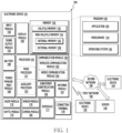
- FIG. 1 is a block diagram illustrating an electronic device 101 in a network environment 100 according to various embodiments.
- the electronic device 101 in the network environment 100 may communicate with an electronic device 102 via a first network 198 (e.g., a short-range wireless communication network), or at least one of an electronic device 104 or a server 108 via a second network 199 (e.g., a long-range wireless communication network).
- the electronic device 101 may communicate with the electronic device 104 via the server 108.
- the auxiliary processor 123 may control at least some of functions or states related to at least one component (e.g., the display module 160, the sensor module 176, or the communication module 190) among the components of the electronic device 101, instead of the main processor 121 while the main processor 121 is in an inactive (e.g., sleep) state, or together with the main processor 121 while the main processor 121 is in an active state (e.g., executing an application).
- the auxiliary processor 123 e.g., an image signal processor or a communication processor
- the auxiliary processor 123 may include a hardware structure specified for artificial intelligence model processing.
- An artificial intelligence model may be generated by machine learning. Such learning may be performed, e.g., by the electronic device 101 where the artificial intelligence is performed or via a separate server (e.g., the server 108). Learning algorithms may include, but are not limited to, e.g., supervised learning, unsupervised learning, semi-supervised learning, or reinforcement learning.
- the artificial intelligence model may include a plurality of artificial neural network layers.
- the artificial neural network may be a deep neural network (DNN), a convolutional neural network (CNN), a recurrent neural network (RNN), a restricted boltzmann machine (RBM), a deep belief network (DBN), a bidirectional recurrent deep neural network (BRDNN), deep Q-network or a combination of two or more thereof but is not limited thereto.
- the artificial intelligence model may, additionally or alternatively, include a software structure other than the hardware structure.
- the memory 130 may store various data used by at least one component (e.g., the processor 120 or the sensor module 176) of the electronic device 101.
- the various data may include, for example, software (e.g., the program 140) and input data or output data for a command related thereto.
- the memory 130 may include the volatile memory 132 or the non-volatile memory 134.
- the program 140 may be stored in the memory 130 as software, and may include, for example, an operating system (OS) 142, middleware 144, or an application 146.
- OS operating system
- middleware middleware
- application application
- the input module 150 may receive a command or data to be used by another component (e.g., the processor 120) of the electronic device 101, from the outside (e.g., a user) of the electronic device 101.
- the input module 150 may include, for example, a microphone, a mouse, a keyboard, a key (e.g., a button), or a digital pen (e.g., a stylus pen).
- the sound output module 155 may output sound signals to the outside of the electronic device 101.
- the sound output module 155 may include, for example, a speaker or a receiver.
- the speaker may be used for general purposes, such as playing multimedia or playing record.
- the receiver may be used for receiving incoming calls. According to an embodiment, the receiver may be implemented as separate from, or as part of the speaker.
- the display module 160 may visually provide information to the outside (e.g., a user) of the electronic device 101.
- the display module 160 may include, for example, a display, a hologram device, or a projector and control circuitry to control a corresponding one of the display, hologram device, and projector.
- the display module 160 may include a touch sensor adapted to detect a touch, or a pressure sensor adapted to measure the intensity of force incurred by the touch.
- the audio module 170 may convert a sound into an electrical signal and vice versa. According to an embodiment, the audio module 170 may obtain the sound via the input module 150, or output the sound via the sound output module 155 or a headphone of an external electronic device (e.g., an electronic device 102) directly (e.g., wiredly) or wirelessly coupled with the electronic device 101.
- an external electronic device e.g., an electronic device 102
- directly e.g., wiredly
- wirelessly e.g., wirelessly
- the sensor module 176 may detect an operational state (e.g., power or temperature) of the electronic device 101 or an environmental state (e.g., a state of a user) external to the electronic device 101, and then generate an electrical signal or data value corresponding to the detected state.
- the sensor module 176 may include, for example, a gesture sensor, a gyro sensor, an atmospheric pressure sensor, a magnetic sensor, an acceleration sensor, a grip sensor, a proximity sensor, a color sensor, an infrared (IR) sensor, a biometric sensor, a temperature sensor, a humidity sensor, or an illuminance sensor.
- the interface 177 may support one or more specified protocols to be used for the electronic device 101 to be coupled with the external electronic device (e.g., the electronic device 102) directly (e.g., wiredly) or wirelessly.
- the interface 177 may include, for example, a high definition multimedia interface (HDMI), a universal serial bus (USB) interface, a secure digital (SD) card interface, or an audio interface.
- HDMI high definition multimedia interface
- USB universal serial bus
- SD secure digital
- a connecting terminal 178 may include a connector via which the electronic device 101 may be physically connected with the external electronic device (e.g., the electronic device 102).
- the connecting terminal 178 may include, for example, an HDMI connector, a USB connector, a SD card connector, or an audio connector (e.g., a headphone connector).
- the haptic module 179 may convert an electrical signal into a mechanical stimulus (e.g., a vibration or a movement) or electrical stimulus which may be recognized by a user via his tactile sensation or kinesthetic sensation.
- the haptic module 179 may include, for example, a motor, a piezoelectric element, or an electric stimulator.
- the camera module 180 may capture a still image or moving images.
- the camera module 180 may include one or more lenses, image sensors, image signal processors, or flashes.
- the power management module 188 may manage power supplied to the electronic device 101.
- the power management module 188 may be implemented as at least part of, for example, a power management integrated circuit (PMIC).
- PMIC power management integrated circuit
- the battery 189 may supply power to at least one component of the electronic device 101.
- the battery 189 may include, for example, a primary cell which is not rechargeable, a secondary cell which is rechargeable, or a fuel cell.
- the communication module 190 may support establishing a direct (e.g., wired) communication channel or a wireless communication channel between the electronic device 101 and the external electronic device (e.g., the electronic device 102, the electronic device 104, or the server 108) and performing communication via the established communication channel.
- the communication module 190 may include one or more communication processors that are operable independently from the processor 120 (e.g., the application processor (AP)) and supports a direct (e.g., wired) communication or a wireless communication.
- AP application processor
- the communication module 190 may include a wireless communication module 192 (e.g., a cellular communication module, a short-range wireless communication module, or a global navigation satellite system (GNSS) communication module) or a wired communication module 194 (e.g., a local area network (LAN) communication module or a power line communication (PLC) module).
- a wireless communication module 192 e.g., a cellular communication module, a short-range wireless communication module, or a global navigation satellite system (GNSS) communication module
- GNSS global navigation satellite system
- wired communication module 194 e.g., a local area network (LAN) communication module or a power line communication (PLC) module.
- LAN local area network
- PLC power line communication
- a corresponding one of these communication modules may communicate with the external electronic device via the first network 198 (e.g., a short-range communication network, such as Bluetooth TM , wireless-fidelity (Wi-Fi) direct, or infrared data association (IrDA)) or the second network 199 (e.g., a long-range communication network, such as a legacy cellular network, a 5G network, a next-generation communication network, the Internet, or a computer network (e.g., LAN or wide area network (WAN)).
- first network 198 e.g., a short-range communication network, such as Bluetooth TM , wireless-fidelity (Wi-Fi) direct, or infrared data association (IrDA)
- the second network 199 e.g., a long-range communication network, such as a legacy cellular network, a 5G network, a next-generation communication network, the Internet, or a computer network (e.g., LAN or wide area network (WAN)).
- the wireless communication module 192 may identify and authenticate the electronic device 101 in a communication network, such as the first network 198 or the second network 199, using subscriber information (e.g., international mobile subscriber identity (IMSI)) stored in the subscriber identification module 196.
- subscriber information e.g., international mobile subscriber identity (IMSI)
- the wireless communication module 192 may support a 5G network, after a 4G network, and next-generation communication technology, e.g., new radio (NR) access technology.
- the NR access technology may support enhanced mobile broadband (eMBB), massive machine type communications (mMTC), or ultra-reliable and low-latency communications (URLLC).
- eMBB enhanced mobile broadband
- mMTC massive machine type communications
- URLLC ultra-reliable and low-latency communications
- the wireless communication module 192 may support a high-frequency band (e.g., the mmWave band) to achieve, e.g., a high data transmission rate.
- the wireless communication module 192 may support various technologies for securing performance on a high-frequency band, such as, e.g., beamforming, massive multiple-input and multiple-output (massive MIMO), full dimensional MIMO (FD-MIMO), array antenna, analog beam-forming, or large scale antenna.
- the wireless communication module 192 may support various requirements specified in the electronic device 101, an external electronic device (e.g., the electronic device 104), or a network system (e.g., the second network 199).
- the wireless communication module 192 may support a peak data rate (e.g., 20Gbps or more) for implementing eMBB, loss coverage (e.g., 164dB or less) for implementing mMTC, or U-plane latency (e.g., 0.5ms or less for each of downlink (DL) and uplink (UL), or a round trip of 1ms or less) for implementing URLLC.
- a peak data rate e.g., 20Gbps or more
- loss coverage e.g., 164dB or less
- U-plane latency e.g., 0.5ms or less for each of downlink (DL) and uplink (UL), or a round trip of 1ms or less
- the signal or the power may then be transmitted or received between the communication module 190 and the external electronic device via the selected at least one antenna.
- another component e.g., a radio frequency integrated circuit (RFIC)
- RFIC radio frequency integrated circuit
- the antenna module 197 may form a mmWave antenna module.
- the mmWave antenna module may include a printed circuit board, an RFIC disposed on a first surface (e.g., the bottom surface) of the printed circuit board, or adjacent to the first surface and capable of supporting a designated high-frequency band (e.g., the mmWave band), and a plurality of antennas (e.g., array antennas) disposed on a second surface (e.g., the top or a side surface) of the printed circuit board, or adjacent to the second surface and capable of transmitting or receiving signals of the designated high-frequency band.
- a designated high-frequency band e.g., the mmWave band
- a plurality of antennas e.g., array antennas
- At least some of the above-described components may be coupled mutually and communicate signals (e.g., commands or data) therebetween via an inter-peripheral communication scheme (e.g., a bus, general purpose input and output (GPIO), serial peripheral interface (SPI), or mobile industry processor interface (MIPI)).
- an inter-peripheral communication scheme e.g., a bus, general purpose input and output (GPIO), serial peripheral interface (SPI), or mobile industry processor interface (MIPI)
- commands or data may be transmitted or received between the electronic device 101 and the external electronic device 104 via the server 108 coupled with the second network 199.
- Each of the electronic devices 102 or 104 may be a device of a same type as, or a different type, from the electronic device 101.
- all or some of operations to be executed at the electronic device 101 may be executed at one or more of the external electronic devices 102, 104, or 108. For example, if the electronic device 101 should perform a function or a service automatically, or in response to a request from a user or another device, the electronic device 101, instead of, or in addition to, executing the function or the service, may request the one or more external electronic devices to perform at least part of the function or the service.
- the one or more external electronic devices receiving the request may perform the at least part of the function or the service requested, or an additional function or an additional service related to the request, and transfer an outcome of the performing to the electronic device 101.
- the electronic device 101 may provide the outcome, with or without further processing of the outcome, as at least part of a reply to the request.
- a cloud computing, distributed computing, mobile edge computing (MEC), or client-server computing technology may be used, for example.
- the electronic device 101 may provide ultra low-latency services using, e.g., distributed computing or mobile edge computing.
- the external electronic device 104 may include an internet-of-things (IoT) device.
- the server 108 may be an intelligent server using machine learning and/or a neural network.
- each of such phrases as “A or B,” “at least one of A and B,” “at least one of A or B,” “A, B, or C,” “at least one of A, B, and C,” and “at least one of A, B, or C,” may include any one of or all possible combinations of the items enumerated together in a corresponding one of the phrases.
- such terms as “1st” and “2nd,” or “first” and “second” may be used to simply distinguish a corresponding component from another, and does not limit the components in other aspect (e.g., importance or order).
- an element e.g., a first element
- operatively or “communicatively”, as “coupled with,” or “connected with” another element
- the element may be coupled with the other element directly (e.g., wiredly), wirelessly, or via a third element.
- module may include a unit implemented in hardware, software, or firmware, and may interchangeably be used with other terms, for example, “logic,” “logic block,” “part,” or “circuitry”.
- a module may be a single integral component, or a minimum unit or part thereof, adapted to perform one or more functions.
- the module may be implemented in a form of an application-specific integrated circuit (ASIC).
- ASIC application-specific integrated circuit
- Various embodiments as set forth herein may be implemented as software (e.g., the program 140) including one or more instructions that are stored in a storage medium (e.g., internal memory 136 or external memory 138) that is readable by a machine (e.g., the electronic device 101).
- a processor e.g., the processor 120
- the machine e.g., the electronic device 101
- the one or more instructions may include a code generated by a complier or a code executable by an interpreter.
- the machine-readable storage medium may be provided in the form of a non-transitory storage medium.
- non-transitory simply means that the storage medium is a tangible device, and does not include a signal (e.g., an electromagnetic wave), but this term does not differentiate between a case in which data is semi-permanently stored in the storage medium and a case in which the data is temporarily stored in the storage medium.
- a method may be included and provided in a computer program product.
- the computer program product may be traded as a product between a seller and a buyer.
- the computer program product may be distributed in the form of a machine-readable storage medium (e.g., compact disc read only memory (CD-ROM)), or be distributed (e.g., downloaded or uploaded) online via an application store (e.g., PlayStore TM ), or between two user devices (e.g., smart phones) directly. If distributed online, at least part of the computer program product may be temporarily generated or at least temporarily stored in the machine-readable storage medium, such as memory of the manufacturer's server, a server of the application store, or a relay server.
- CD-ROM compact disc read only memory
- an application store e.g., PlayStore TM
- two user devices e.g., smart phones
- each component e.g., a module or a program of the above-described components may include a single entity or multiple entities, and some of the multiple entities may be separately disposed in different components. According to various embodiments, one or more of the above-described components may be omitted, or one or more other components may be added. Alternatively or additionally, a plurality of components (e.g., modules or programs) may be integrated into a single component. In such a case, according to various embodiments, the integrated component may still perform one or more functions of each of the plurality of components in the same or similar manner as they are performed by a corresponding one of the plurality of components before the integration.
- operations performed by the module, the program, or another component may be carried out sequentially, in parallel, repeatedly, or heuristically, or one or more of the operations may be executed in a different order or omitted, or one or more other operations may be added.
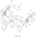
- FIG. 2A illustrates an example of a perspective view of a wearable device according to an embodiment.
- FIG. 2B illustrates an example of one or more hardware disposed in a wearable device according to an embodiment.
- the wearable device 101 may have a shape of glasses wearable on a user's body part (e.g., head).
- the wearable device 101 of FIGS. 2A and 2B may be an example of the electronic device 101 of FIG. 1 .
- the wearable device 101 may include a head-mounted display (HMD).
- a housing of the wearable device 101 may include flexible materials, such as rubber and/or silicone, that have a shape closely fitting a part (e.g., a part of the face surrounding both eyes) of the user's head.
- the housing of the wearable device 101 may include one or more straps able to be twined around the user's head and/or one or more temples attachable to ear of the head.
- the wearable device 101 may include at least one display 250 and a frame 200 supporting the at least one display 250.
- the wearable device 101 may be wearable on a portion of the user's body.
- the wearable device 101 may provide augmented reality (AR), virtual reality (VR), or mixed reality (MR) combining the augmented reality and the virtual reality to a user wearing the wearable device 101.
- AR augmented reality
- VR virtual reality
- MR mixed reality
- the wearable device 101 may display a virtual reality image provided from at least one optical device 282 and 284 of FIG. 2B on at least one display 250, in response to a user's preset gesture obtained through a motion recognition camera 260-2 and 264 of FIG. 2B .
- the at least one display 250 may provide visual information to a user.
- the at least one display 250 may include a transparent or translucent lens.
- the at least one display 250 may include a first display 250-1 and/or a second display 250-2 spaced apart from the first display 250-1.
- the first display 250-1 and the second display 250-2 may be disposed at positions corresponding to the user's left and right eyes, respectively.
- the at least one display 250 may provide visual information transmitted through a lens included in at least one display 250 from ambient light to a user and other visual information distinguished from the visual information.
- the lens may be formed based on at least one of a fresnel lens, a pancake lens, or a multi-channel lens.
- the at least one display 250 may include a first surface 231 and a second surface 232 opposite to the first surface 231.
- a display area may be formed on the second surface 232 of at least one display 250.
- ambient light may be transmitted to the user by being incident on the first surface 231 and being penetrated through the second surface 232.
- the at least one display 250 may display an augmented reality image in which a virtual reality image provided by the at least one optical device 282 and 284 is combined with a reality screen transmitted through ambient light, on a display area formed on the second surface 232.
- the at least one display 250 may include at least one waveguide 233 and 234 that transmits light transmitted from the at least one optical device 282 and 284 by diffracting to the user.
- the at least one waveguide 233 and 234 may be formed based on at least one of glass, plastic, or polymer.
- a nano pattern may be formed on at least a portion of the outside or inside of the at least one waveguide 233 and 234.
- the nano pattern may be formed based on a grating structure having a polygonal or curved shape. Light incident to an end of the at least one waveguide 233 and 234 may be propagated to another end of the at least one waveguide 233 and 234 by the nano pattern.
- the at least one waveguide 233 and 234 may include at least one of at least one diffraction element (e.g., a diffractive optical element (DOE), a holographic optical element (HOE)), and a reflection element (e.g., a reflection mirror).
- the at least one waveguide 233 and 234 may be disposed in the wearable device 101 to guide a screen displayed by the at least one display 250 to the user's eyes.
- the screen may be transmitted to the user's eyes through total internal reflection (TIR) generated in the at least one waveguide 233 and 234.
- TIR total internal reflection
- the wearable device 101 may analyze an object included in a real image collected through a photographing camera 245, combine with a virtual object corresponding to an object that become a subject of augmented reality provision among the analyzed object, and display on the at least one display 250.
- the virtual object may include at least one of text and images for various information associated with the object included in the real image.
- the wearable device 101 may analyze the object based on a multi-camera such as a stereo camera. For the object analysis, the wearable device 101 may execute simultaneous localization and mapping (SLAM) and/or time-of-flight (ToF), supported by the multi-camera.
- SLAM simultaneous localization and mapping
- ToF time-of-flight
- the user wearing the wearable device 101 may watch an image displayed on the at least one display 250.
- a frame 200 may be configured with a physical structure in which the wearable device 101 may be worn on the user's body. According to an embodiment, the frame 200 may be configured so that when the user wears the wearable device 101, the first display 250-1 and the second display 250-2 may be positioned corresponding to the user's left and right eyes.
- the frame 200 may support the at least one display 250. For example, the frame 200 may support the first display 250-1 and the second display 250-2 to be positioned at positions corresponding to the user's left and right eyes.
- the frame 200 may include an area 220 at least partially in contact with the portion of the user's body in case that the user wears the wearable device 101.
- the area 220 of the frame 200 in contact with the portion of the user's body may include an area in contact with a portion of the user's nose, a portion of the user's ear, and a portion of the side of the user's face that the wearable device 101 contacts.
- the frame 200 may include a nose pad 210 that is contacted on the portion of the user's body. When the wearable device 101 is worn by the user, the nose pad 210 may be contacted on the portion of the user's nose.
- the frame 200 may include a first temple 204 and a second temple 205, which are contacted on another portion of the user's body that is distinct from the portion of the user's body.
- the frame 200 may include a first rim 201 surrounding at least a portion of the first display 250-1, a second rim 202 surrounding at least a portion of the second display 250-2, a bridge 203 disposed between the first rim 201 and the second rim 202, a first pad 211 disposed along a portion of the edge of the first rim 201 from one end of the bridge 203, a second pad 212 disposed along a portion of the edge of the second rim 202 from the other end of the bridge 203, the first temple 204 extending from the first rim 201 and fixed to a portion of the wearer's ear, and the second temple 205 extending from the second rim 202 and fixed to a portion of the ear opposite to the ear.
- the first pad 211 and the second pad 212 may be in contact with the portion of the user's nose, and the first temple 204 and the second temple 205 may be in contact with a portion of the user's face and the portion of the user's ear.
- the temples 204 and 205 may be rotatably connected to the rim through hinge units 206 and 207 of FIG. 2B .
- the first temple 204 may be rotatably connected with respect to the first rim 201 through the first hinge unit 206 disposed between the first rim 201 and the first temple 204.
- the second temple 205 may be rotatably connected with respect to the second rim 202 through the second hinge unit 207 disposed between the second rim 202 and the second temple 205.
- the wearable device 101 may identify an external object (e.g., a user's fingertip) touching the frame 200 and/or a gesture performed by the external object by using a touch sensor, a grip sensor, and/or a proximity sensor formed on at least a portion of the surface of the frame 200.
- an external object e.g., a user's fingertip
- the wearable device 101 may include hardware (e.g., hardware to be described later based on a block diagram of FIG. 4 ) that performs various functions.
- the hardware may include a battery module 270, an antenna module 275, the at least one optical device 282 and 284, speakers (e.g., speakers 255-1 and 255-2), a microphone (e.g., microphones 265-1, 265-2, and 265-3), a light emitting module (not illustrated), and/or a printed circuit board (PCB) 290 (e.g., printed circuit board).
- Various hardware may be disposed in the frame 200.
- the microphone e.g., the microphones 265-1, 265-2, and 265-3) of the wearable device 101 may obtain a sound signal, by being disposed on at least a portion of the frame 200.
- the first microphone 265-1 disposed on the nose pad 210, the second microphone 265-2 disposed on the second rim 202, and the third microphone 265-3 disposed on the first rim 201 are illustrated in FIG. 2B , but the number and disposition of the microphone 265 are not limited to an embodiment of FIG. 2B .
- the wearable device 101 may identify a direction of the sound signal by using a plurality of microphones disposed on different portions of the frame 200.
- the at least one optical device 282 and 284 may project a virtual object on the at least one display 250 in order to provide various image information to the user.
- the at least one optical device 282 and 284 may be a projector.
- the at least one optical device 282 and 284 may be disposed adjacent to the at least one display 250 or may be included in the at least one display 250 as a portion of the at least one display 250.
- the wearable device 101 may include a first optical device 282 corresponding to the first display 250-1, and a second optical device 284 corresponding to the second display 250-2.
- the at least one optical device 282 and 284 may include the first optical device 282 disposed at a periphery of the first display 250-1 and the second optical device 284 disposed at a periphery of the second display 250-2.
- the first optical device 282 may transmit light to the first waveguide 233 disposed on the first display 250-1
- the second optical device 284 may transmit light to the second waveguide 234 disposed on the second display 250-2.
- a camera 260 may include the photographing camera 245, an eye tracking camera (ET CAM) 260-1, and/or the motion recognition camera 260-2.
- the photographing camera 245, the eye tracking camera 260-1, and the motion recognition camera 260-2 and 264 may be disposed at different positions on the frame 200 and may perform different functions.
- the eye tracking camera 260-1 may output data indicating a gaze of the user wearing the wearable device 101.
- the wearable device 101 may detect the gaze from an image including the user's pupil obtained through the eye tracking camera 260-1.
- An example in which the eye tracking camera 260-1 is disposed toward the user's right eye is illustrated in FIG. 2B , but the embodiment is not limited thereto, and the eye tracking camera 260-1 may be disposed alone toward the user's left eye or may be disposed toward two eyes.
- the photographing camera 245 may photograph a real image or background to be matched with a virtual image in order to implement the augmented reality or mixed reality content.
- the photographing camera 245 may photograph an image of a specific object existing at a position viewed by the user and may provide the image to the at least one display 250.
- the at least one display 250 may display one image in which a virtual image provided through the at least one optical device 282 and 284 is overlapped with information on the real image or background including an image of the specific object obtained by using the photographing camera 245.
- the photographing camera 245 may be disposed on the bridge 203 disposed between the first rim 201 and the second rim 202.
- the eye tracking camera 260-1 may implement a more realistic augmented reality by matching the user's gaze with the visual information provided on the at least one display 250, by tracking the gaze of the user wearing the wearable device 101. For example, when the user looks at the front, the wearable device 101 may naturally display environment information associated with the user's front on the at least one display 250 at a position where the user is positioned.
- the eye tracking camera 260-1 may be configured to capture an image of the user's pupil in order to determine the user's gaze. For example, the eye tracking camera 260-1 may receive gaze detection light reflected from the user's pupil and may track the user's gaze based on the position and movement of the received gaze detection light.
- the eye tracking camera 260-1 may be disposed at a position corresponding to the user's left and right eyes.
- the eye tracking camera 260-1 may be disposed in the first rim 201 and/or the second rim 202 to face the direction in which the user wearing the wearable device 101 is positioned.
- the motion recognition camera 260-2 and 264 may provide a specific event to the screen provided on the at least one display 250 by recognizing the movement of the whole or portion of the user's body, such as the user's torso, hand, or face.
- the motion recognition camera 260-2 and 264 may obtain a signal corresponding to motion by recognizing the user's motion (e.g., gesture recognition), and may provide a display corresponding to the signal to the at least one display 250.
- the processor may identify a signal corresponding to the operation and may perform a preset function based on the identification.
- the motion recognition camera 260-2 and camera 264 may be disposed on the first rim 201 and/or the second rim 202.
- the camera 260 included in the wearable device 101 is not limited to the above-described eye tracking camera 260-1 and the motion recognition camera 260-2 and 264.
- the wearable device 101 may identify an external object included in the FoV by using a camera 260 disposed toward the user's FoV. Identifying of the external object by the wearable device 101 may be performed based on a sensor for identifying a distance between the wearable device 101 and the external object, such as a depth sensor and/or a time of flight (ToF) sensor.
- the camera 260 disposed toward the FoV may support an autofocus function and/or an optical image stabilization (OIS) function.
- the wearable device 101 may include the camera 260 (e.g., a face tracking (FT) camera) disposed toward the face.
- FT face tracking
- the wearable device 101 may further include a light source (e.g., LED) that emits light toward a subject (e.g., user's eyes, face, and/or an external object in the FoV) photographed by using the camera 260.
- the light source may include an LED having an infrared wavelength.
- the light source may be disposed on at least one of the frame 200, and the hinge units 206 and 207.
- the battery module 270 may supply power to electronic components of the wearable device 101.
- the battery module 270 may be disposed in the first temple 204 and/or the second temple 205.
- the battery module 270 may be a plurality of battery modules 270.
- the plurality of battery modules 270 respectively, may be disposed on each of the first temple 204 and the second temple 205.
- the battery module 270 may be disposed at an end of the first temple 204 and/or the second temple 205.
- the antenna module 275 may transmit the signal or power to the outside of the wearable device 101 or may receive the signal or power from the outside.
- the antenna module 275 may be disposed in the first temple 204 and/or the second temple 205.
- the antenna module 275 may be disposed close to one surface of the first temple 204 and/or the second temple 205.
- a speaker 255 may output a sound signal to the outside of the wearable device 101.
- a sound output module may be referred to as a speaker.
- the speaker 255 may be disposed in the first temple 204 and/or the second temple 205 in order to be disposed adjacent to the ear of the user wearing the wearable device 101.
- the speaker 255 may include a second speaker 255-2 disposed adjacent to the user's left ear by being disposed in the first temple 204, and a first speaker 255-1 disposed adjacent to the user's right ear by being disposed in the second temple 205.
- the light emitting module may include at least one light emitting element.
- the light emitting module may emit light of a color corresponding to a specific state or may emit light through an operation corresponding to the specific state in order to visually provide information on a specific state of the wearable device 101 to the user. For example, when the wearable device 101 requires charging, it may emit red light at a constant cycle.
- the light emitting module may be disposed on the first rim 201 and/or the second rim 202.
- the wearable device 101 may include the printed circuit board (PCB) 290.
- the PCB 290 may be included in at least one of the first temple 204 or the second temple 205.
- the PCB 290 may include an interposer disposed between at least two sub PCBs.
- one or more hardware e.g., hardware illustrated by different blocks of FIG. 4
- the wearable device 101 may include a flexible PCB (FPCB) for interconnecting the hardware.
- FPCB flexible PCB
- the wearable device 101 may include at least one of a gyro sensor, a gravity sensor, and/or an acceleration sensor for detecting the posture of the wearable device 101 and/or the posture of a body part (e.g., a head) of the user wearing the wearable device 101.
- a gravity sensor and the acceleration sensor may measure gravity acceleration, and/or acceleration based on preset 3-dimensional axes (e.g., x-axis, y-axis, and z-axis) perpendicular to each other.
- the gyro sensor may measure angular velocity of each of preset 3-dimensional axes (e.g., x-axis, y-axis, and z-axis).
- At least one of the gravity sensor, the acceleration sensor, and the gyro sensor may be referred to as an inertial measurement unit (IMU).
- the wearable device 101 may identify the user's motion and/or gesture performed to execute or stop a specific function of the wearable device 101 based on the IMU.
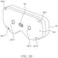
- FIGS. 3A to 3B illustrate an example of an exterior of a wearable device according to an embodiment.
- a wearable device 101 of FIGS. 3A to 3B may be an example of the electronic device 101 of FIG. 1 .
- an example of the exterior of a first surface 310 of the housing of the wearable device 101 may be illustrated in FIG. 3A
- an example of the exterior of a second surface 320 opposite to the first surface 310 may be illustrated in FIG. 3B .
- the first surface 310 of the wearable device 101 may have an attachable shape on the user's body part (e.g., the user's face).
- the wearable device 101 may further include a strap for being fixed on the user's body part, and/or one or more temples (e.g., the first temple 204 and/or the second temple 205 of FIGS. 2A to 2B ).
- a first display 250-1 for outputting an image to the left eye among the user's two eyes and a second display 250-2 for outputting an image to the right eye among the user's two eyes may be disposed on the first surface 310.
- the wearable device 101 may further include rubber or silicon packing, which are formed on the first surface 310, for preventing interference by light (e.g., ambient light) different from the light emitted from the first display 250-1 and the second display 250-2.
- the wearable device 101 may include cameras 260-3 and 260-4 for photographing and/or tracking two eyes of the user adjacent to each of the first display 250-1 and the second display 250-2.
- the cameras 260-3 and 260-4 may be referred to as an ET camera.
- the wearable device 101 may include cameras 260-5 and 260-6 for photographing and/or recognizing the user's face.
- the cameras 260-5 and 260-6 may be referred to as a FT camera.
- a camera e.g., cameras 260-7, 260-8, 260-9, 260-10, 260-11, and 260-12
- a sensor e.g., the depth sensor 330
- the cameras 260-7, 260-8, 260-9, and 260-10 may be disposed on the second surface 320 in order to recognize an external object different from the wearable device 101.
- the wearable device 101 may obtain an image and/or video to be transmitted to each of the user's two eyes.
- the camera 260-11 may be disposed on the second surface 320 of the wearable device 101 to obtain an image to be displayed through the second display 250-2 corresponding to the right eye among the two eyes.
- the camera 260-12 may be disposed on the second surface 320 of the wearable device 101 to obtain an image to be displayed through the first display 250-1 corresponding to the left eye among the two eyes.
- the wearable device 101 may include the depth sensor 330 disposed on the second surface 320 in order to identify a distance between the wearable device 101 and the external object.
- the wearable device 101 may obtain spatial information (e.g., a depth map) about at least a portion of the FoV of the user wearing the wearable device 101.
- a microphone for obtaining sound outputted from an external object may be disposed on the second surface 320 of the wearable device 101.
- the number of microphones may be one or more according to an embodiment.
- the wearable device 101 may include hardware (e.g., cameras 240-11 and 240-12, and/or the depth sensor 330) for identifying a body part including a user's hand.
- the wearable device 101 may identify a gesture indicated by a motion of a body part.
- the wearable device 101 may provide a UI based on the identified gesture to a user wearing the wearable device 101.
- the UI may support a function for editing an image and/or video stored in the wearable device 101.
- the wearable device 101 may communicate with an external electronic device different from the wearable device 101, in order to more accurately identify the gesture.
- FIG. 4 is an exemplary block diagram of a wearable device according to an embodiment.
- a wearable device 101 of FIG. 4 may be an example of the electronic device 101 of FIG. 1 and the wearable device 101 of FIGS. 2A and 2B .
- the wired network may include a network such as Internet, a local area network (LAN), a wide area network (WAN), Ethernet, or a combination thereof.
- LAN local area network
- WAN wide area network
- Ethernet or a combination thereof.
- the wearable device 101 may include at least one of a processor 120, memory 130, cameras 410 and 420, a display 450, a sensor 470, or communication circuitry 480.
- the processor 120, the memory 130, the cameras 410 and 420, the display 450, the sensor 470, and the communication circuitry 480 may be electronically and/or operably coupled with each other by an electronical component such as a communication bus.
- an electronical component such as a communication bus.
- hardware components being operably coupled may mean that a direct connection or an indirect connection between the hardware components is established by wire or wirelessly such that a second hardware component among the hardware components is controlled by a first hardware component.
- an embodiment is not limited thereto, and a portion (e.g., at least a portion of the processor 120, the memory 130, and the communication circuitry 480) of the hardware components illustrated in FIG. 4 may be included in a single integrated circuit such as a system on a chip (SoC).
- SoC system on a chip
- a type and/or the number of hardware components included in the wearable device 101 is not limited as illustrated in FIG. 4 .
- the wearable device 101 may include only a portion of the hardware components illustrated in FIG. 4 .
- the processor 120 of the wearable device 101 may include a hardware component for processing data based on one or more instructions.
- the hardware component for processing the data may include an arithmetic and logic unit (ALU), a floating point unit (FPU), a field programmable gate array (FPGA), and/or a central processing unit (CPU).
- the number of the processors 120 may be one or more.
- the processor 120 may have a structure of a multi-core processor such as a dual core, a quad core, or a hexa core.
- the processor 120 of FIG. 4 may include the processor 120 of FIG. 1 .
- the memory 130 of the wearable device 101 may include a hardware component for storing the data and/or an instruction inputted to or outputted from the processor 120.
- the memory 130 may include, for example, a volatile memory such as a random-access memory (RAM), and/or a non-volatile memory such as a read-only memory (ROM).
- the volatile memory may include at least one of a dynamic RAM (DRAM), a static RAM (SRAM), a Cache RAM, and a pseudo SRAM (PSRAM).
- DRAM dynamic RAM
- SRAM static RAM
- PSRAM pseudo SRAM
- the non-volatile memory may include at least one of, for example, a programmable ROM (PROM), an erasable PROM (EPROM), an electrically erasable PROM (EEPROM), a flash memory, a hard disk, a compact disk, and an embedded multi media card (eMMC).
- PROM programmable ROM
- EPROM erasable PROM
- EEPROM electrically erasable PROM
- flash memory a hard disk
- eMMC embedded multi media card
- the memory 130 of FIG. 4 may include the memory 130 of FIG. 1 .
- one or more instructions indicating a calculation and/or an operation to be performed by the processor 120 on data may be stored.
- a set of one or more instructions may be referred to as firmware, an operating system, a process, a routine, a sub-routine and/or an application.
- the wearable device 101 and/or the processor 120 may perform at least one of operations of FIGS. 7 , 9 , or 11 , when a set of a plurality of instructions distributed in a form of the operating system, the firmware, a driver, and/or the application is executed.
- the application being installed in the wearable device 101 may mean that the one or more instructions provided in a form of the application are stored in the memory 130 of the wearable device 101, and the one or more applications are stored in an executable format (e.g., a file having an extension specified by the operating system of the wearable device 101).
- an executable format e.g., a file having an extension specified by the operating system of the wearable device 101.
- the one or more applications may be installed in the memory 130 of the wearable device 101.
- the one or more instructions included in the one or more applications may be divided into an identifier for predicting a gaze of a user, a discriminator for discriminating a position corresponding to a direction of eyes and whether the gaze is corresponded, and/or a compensator for compensating the position corresponding to the direction of the eyes.
- the wearable device 101 may predict whether the gaze of the user matches an external object (or a subject) displayed or shown within a FoV of the wearable device 101, in a state that the identifier is executed. An operation in which the wearable device 101 identifies the gaze of the user using the external object (e.g., a visual object) will be described later in FIGS. 6A to 6C .
- the second camera 420 of the wearable device 101 may identify the eyes of the user wearing the wearable device 101.
- the second camera 420 may be disposed toward the eyes of the user.
- the second camera 420 may be referred to the gaze tracking camera 260-1 of FIG. 2A .
- the wearable device 101 may infer the eyes direction of the user based on identifying a position of each of a pupil, a sclera, an iris, and/or a glint (e.g., gaze detection light reflected from the pupil), included in the eyes of the user, using the second camera 420.
- the wearable device 101 may infer the direction of the eyes of the user, located within the field-of-view (FoV) of the wearable device 101.
- FoV field-of-view
- a FoV of the cameras 410 and 420 is an area formed based on a view angle in which lenses of the cameras 410 and 420 are capable of receiving light, and may correspond to an area corresponding to the image generated by the cameras 410 and 420.
- the subject, the visual object, and/or the external object means an object included in the FoV of the cameras 410 and 420 and distinguished from the wearable device 101.
- the FoV of the cameras 410 and 420 may at least partially match an environment shown to the user through the display 450, such as a FoV 510 of FIG. 5 to be described later. At least one of the cameras 410 and 420 may include the camera module 180 of FIG. 1 .
- the wearable device 101 may include another output means for outputting information in a form other than a visual form and an auditory form.
- the wearable device 101 may include at least one speaker for outputting an audio signal, and/or a motor (or actuator) for providing haptic feedback based on vibration.
- the sensor 470 of the wearable device 101 may generate electronic information that may be processed by the processor 120 and/or the memory 130 from non-electronic information related to the wearable device 101.
- the electronic information generated by the sensor 470 may be stored in the memory 130, processed by the processor 120, and/or transmitted to another electronic device distinguished from the wearable device 101.
- An embodiment of the wearable device 101 is not limited to a type and/or the number of one or more sensors exemplified in FIG. 4 .
- the senor 470 may further include a grip sensor capable of identifying a contact between the wearable device 101 and an external object (e.g., a user), and/or a gyro sensor or an acceleration sensor capable of identifying a movement of the wearable device 101.
- a grip sensor capable of identifying a contact between the wearable device 101 and an external object (e.g., a user)
- a gyro sensor or an acceleration sensor capable of identifying a movement of the wearable device 101.
- the communication circuitry 480 may include, for example, at least one of a MODEM, an antenna, and an optic/electronic (O/E) converter.
- the communication circuitry 480 may support the transmission and/or the reception of the electrical signal based on various types of protocols such as ethernet, a local area network (LAN), a wide area network (WAN), wireless fidelity (WiFi), Bluetooth, Bluetooth low energy (BLE), ZigBee, long term evolution (LTE), and 5G new radio (NR).
- the communication circuitry 460 of FIG. 4 may include the communication module 190 and/or the antenna module 197 of FIG. 1 .
- the wearable device 101 may display the visual object 515 within the FoV 510 using a display (e.g., the display 450 of FIG. 4 ).
- the visual object 515 may be referred to a virtual object generated by the wearable device 101 to identify a direction (or a gaze of the user) of eyes of the user 505.
- a size and/or a type of the visual object 515 may vary according to an embodiment.
- the wearable device 101 may identify an area 511 in which the visual object 515 is displayed within the FoV 510 by displaying the visual object 515.
- the area 511 may include position information of the visual object 515 within the FoV 510.
- the position information of the visual object 515 may mean a center point of the visual object 515.
- the wearable device 101 may obtain information corresponding to the area 511.
- the information may indicate a probability that the direction of the eyes of the user 505 corresponds to at least a portion of the area 511.
- the information may be obtained based on a feature map (e.g., a saliency map).
- the wearable device 101 may obtain probability information in which the gaze of the user 505 matches an external object displayed or shown within the FoV 510 using the feature map.
- the wearable device 101 may identify information indicating the direction of the eyes of the user 505 looking at the visual object 515 using a second camera 420.
- the information indicating the direction of the eyes may be identified by frames obtained by using the second camera 420.
- the information may be composed of one or more parameters.
- the wearable device 101 may identify a first position 513 corresponding to the information within the FoV 510.
- the first position 513 may be a position identified based on an optical axis of the eyes of the user 505.
- the wearable device 101 may identify an external object that interacts with the visual object 515 based on a first camera (e.g., the first camera 410 of FIG. 4 ).
- the wearable device 101 may identify a second position 517 interacting with the visual object 515 and the external object.
- the second position 517 may be included in the area 511.
- an operation in which the wearable device 101 identifies the interaction will be described later in FIGS. 6A to 6C .
- the wearable device 101 may identify a difference between the second position 517 and the first position 513 within the FoV 510 based on identifying the second position 517.
- the wearable device 101 may identify that a position corresponding to the gaze of the user 505 matches the second position 517, based on identifying the difference less than a specified threshold 519.
- the position corresponding to the gaze of the user 505 may be an example of a position based on a visual axis of the eyes of the user.
- the specified threshold may mean a specified distance between the first position 513 and the second position 517.
- the wearable device 101 may obtain a probability (e.g., 0 to 1) value that the gaze of the user corresponds to the second position 517 using the specified threshold. For example, in case that the distance between the second position 517 and the first position 513 is less than the specified threshold, the wearable device 101 may identify a probability value corresponding to the second position 517 as '1'. However, it is not limited thereto.
- the wearable device 101 may identify the difference between the second position 517 and the first position 513 that is equal to or more than the specified threshold 519.
- the wearable device 101 may display a visual object indicating calibration, using the display, based on identifying the difference. The operation of displaying the visual object will be described later in FIG. 8 .
- the wearable device 101 may change the information indicating the direction of the eyes of the user 505, based on identifying the difference between the second position 517 and the first position 513 that is less than the specified threshold 519. For example, the wearable device 101 may change the information using the second position 517. The wearable device 101 may map the information to correspond to the second position 517. The wearable device 101 may compensate the first position 513 corresponding to the direction of the user obtained by using the second camera 420 using the second position 517. For example, the wearable device 101 may calibrate the first position 513 to the second position 517.
- the wearable device 101 may identify the second position 517 at which the interaction between the visual object 515 and the external object occurs, in first frames obtained by using the first camera 410.
- the wearable device 101 may obtain the information indicating the direction of the eyes of the user in the obtained second frames using the second camera 420.
- the information may include a first position 513.
- the wearable device 101 may accumulate data indicating the second position 517 included in each of the first frames and data indicating the first position 513 included in each of the second frames.
- the wearable device 101 may perform calibration based on the accumulated data. For example, while performing the calibration, the wearable device 101 may display a visual object 520 indicating the calibration within the FoV 510, using the display.
- the wearable device may indicate the calibration to the user using the visual object 520.
- the wearable device 101 may identify whether the obtained information indicating the direction of the eyes and the information indicating the interaction matches by using the second camera 420. For example, the wearable device 101 may improve reliability of an operation of matching a gaze position of the user to the second position 517 by obtaining data indicating whether the matches. Based on the improved reliability, the wearable device 101 may more accurately provide position information corresponding to the gaze of the user within the FoV 510 of the user wearing the wearable device 101.
- FIGS. 6A to 6C an operation in which the wearable device 101 identifies the interaction between the external object and the visual object will be described later.
- FIGS. 6A to 6C illustrate an exemplary an interaction using an external object identified by a wearable device according to an embodiment.
- a wearable device 101 of FIGS. 6A to 6C may be an example of the electronic device 101 of FIG. 1 and/or the wearable device 101 of FIGS. 2A to 5 .
- positions 615-1, 615-2, and 615-3 obtained by the wearable device 101 using a second camera may be referred to the first position 513 of FIG. 5 .
- a second camera e.g., the second camera 420 of FIG. 4
- a state 600 where the wearable device 101 displays a visual object 620 within a FoV 510 is illustrated.
- the wearable device 101 may identify at least one hand 630 of the user 505 of the wearable device 101 while displaying the visual object 620 in the state 600.
- the wearable device 101 may identify the at least one hand 630 using a first camera (e.g., the first camera 410 of FIG. 4 ).
- the wearable device 101 may track the at least one hand 630 shown within the FoV 510.
- the wearable device 101 may identify an interaction between the visual object 620 and the at least one hand 630 while tracking the at least one hand 630. For example, the wearable device 101 may identify a first gesture indicating the at least one hand 630 pointing the visual object 620. For example, the wearable device 101 may identify a visual object 620 matching a direction of a fingertip included in the at least one hand 630. For example, the wearable device 101 may identify a second gesture indicating the at least one hand 630 gripping the visual object 620. For example, the at least one hand 630 may be referred to at least one of the external objects, shown through the FoV 510 of the user.
- the wearable device 101 may identify the visual object 620 matching a direction of the at least one hand 630.
- the interaction between the visual object and the external object is not limited to the above-described embodiment.
- the wearable device 101 may identify an interaction by tracking an external object different from the at least one hand 630.
- the wearable device 101 may identify that the position 616 corresponding to gaze 610 of the user 505 matches a first position of the visual object 620 and/or a second position of the at least one hand 630 based on identifying the interaction. For example, the wearable device 101 may compensate for the position 615-1 (e.g., a position included in information indicating a direction of eyes) obtained using a second camera 420 based on the first position and/or the second position.
- the position 615-1 e.g., a position included in information indicating a direction of eyes
- the wearable device 101 may display a visual object 635 within the FoV 510 in a state 603.
- the visual object 635 may be used to identify the at least one hand 630 of the user 505 of the wearable device 101.
- the wearable device 101 may induce a specified gesture of the user 505 using the visual object 635.
- the specified gesture may be an example of an unlock pattern of the wearable device 101.
- the wearable device 101 may display a screen based on at least one application, using a display, by identifying the specified gesture.
- the wearable device 101 may identify the gaze 610 of the user 505 based on identifying the at least one hand 630 based on the specified gesture.
- the wearable device 101 may infer the gaze 610 of the user 505 based on identifying the at least one hand 630 at the ending position 617 included in the specified gesture.
- the wearable device may change some of information (e.g., the position 615-2) indicating a direction of eyes based on a position of the at least one hand 630.
- the wearable device 101 may obtain information indicating the direction of the eyes of the user 505 using the second camera (e.g., the second camera 420 of FIG. 4 ).
- the information indicating the direction of the eyes may include information indicating the position 615-3 within the FoV 510.
- the wearable device 101 may change the information indicating the direction of the eyes based on identifying the external electronic device 650.
- the wearable device 101 may change the position 615-3 to the position 618 corresponding to the gaze 610 of the user.
- the wearable device 101 may identify an external object (e.g., the visual object 620, the at least one hand 630, or the external electronic device 650) that is shown or displayed within the FoV 510.
- the user of the wearable device 101 may gaze at a position corresponding to the external object.
- the gaze of the user may be matched with the position corresponding to the external object.
- the information indicating the direction of the eyes obtained by the wearable device 101 using the second camera 420 and the gaze of the user may be substantially different.
- the wearable device 101 may improve a user experience for an augmented reality service by changing the information indicating the direction of the eyes using the position corresponding to the external object.
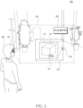
- FIG. 10 illustrates an exemplary operation in which a wearable device according to an embodiment identifies an interaction between a visual object and another user different from a user wearing the wearable device.
- a wearable device 101 of FIG. 10 may be an example of the electronic device 101 of FIG. 1 and/or the wearable device 101 of FIGS. 2A to 9 .
- a state 1000 in which the wearable device 101 identifies another user 1010 different from a user 505 is illustrated within a FoV 510.
- the state 1000 may include a coworking space shared by one or more users 505 and 1010. However, it is not limited thereto.
- the wearable device 101 may display a visual object 1005 within the FoV 510 in the state 1000 using a display (e.g., the display 450 of FIG. 4 ).
- the wearable device 101 may share or transmit position information of the visual object 1005 with the external wearable device 1020 in the space where the wearable device 101 is included.
- the wearable device may identify position information of the visual object.
- the position information of the visual object may include the point where the interaction occurred, a center point of the visual object, and/or an area in which the visual object is displayed within the FoV.
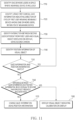
- the wearable device may display a visual object indicating calibration on the display, in an operation 1180.
- the visual object indicating the calibration may be referred to the visual object 805 of FIG. 8 .
- the wearable device may guide the calibration of the user using the visual object.
- the wearable device may change information indicating the direction of the eyes of the user based on the interaction by displaying the visual object for interacting with a hand of the user wearing the wearable device on the display.
- the wearable device may identify information indicating an eye direction of the user, using at least one camera to obtain information corresponding to the gaze of the user.
- the wearable device may change the information indicating the identified the direction of the eyes by displaying the visual object within the FoV of the user.
- a method for compensating for the direction of the eyes of the user wearing the wearable device, corresponding to a point in an image displayed within the FoV of the wearable device is required.
- a wearable device 101 may comprise a first camera 410, a second camera 420, a display 450 and a processor 120.
- the processor may display, using the display, a visual object 515, 620, and 635 within a field of view (FoV) 505 of a user, in a state 500, 600, 603, 605, and 800 where the wearable device is worn by the user 505.
- the processor may, while displaying the visual object, based on the first camera disposed toward the FoV, identify an external object, interacting with the visual object, seen through the FoV.
- the processor may obtain a position of the external object, based on identifying an interaction between the external object and the visual object using the first camera.
- the processor may be configured to change information indicating a direction of eyes identified by frames outputted from the second camera disposed toward the eyes of the user, using at least one of a position of the visual object 511 or the position of the external object, based on obtaining the position of the external object.
- the processor may identify a second user 1010 different from a first user who is the user, in a space where the wearable device is included.
- the processor may be configured to change the information, based on identifying a second interaction of the visual object and the second user different from a first interaction that is the interaction.
- the processor may be configured to identify the second interaction based on identifying the visual object matching a direction of eyes of the second user.
- the external object may include at least one hand 1013 of the second user.
- the processor may be configured to identify the second interaction based on identifying at least one of a third gesture indicating the at least one hand of the second user pointing the visual object or a fourth gesture indicating the at least one hand of the second user gripping the visual object.
- the method may comprise changing information indicating a direction of eyes identified by frames outputted from a second camera 420 disposed toward the eyes of the user, using at least one of a position 511 of the visual object or the position of the external object, based on obtaining the position of the external object.
- the method may comprise changing, within the FoV, a position 513, 615-1, 615-2, 615-3, and 1025 matching the direction of the eyes obtained using the information.
- the method may comprise tracking at least one hand 630 included in the external object, using the first camera.
- the method may comprise changing the information based identifying the interaction of the visual object and the at least one hand.
- the method may comprise identifying the interaction based on identifying at least one of a first gesture indicating the at least one hand pointing the visual object or a second gesture indicating the at least one hand gripping the visual object.
- the method may comprise, while changing the information, displaying, within the FoV, a second visual object 520 indicating changing the information different form a first visual object that is the visual object.
- the method may comprise, based on identifying a difference of the position of the external object and the direction of the eyes equal to or more than a specified threshold 519, displaying a third visual object, to guide to changing positional relations between the wearable device and the eyes.
- the method may comprise, based on identifying the difference of the position of the external object and the direction of the eyes less than the specified threshold 519, changing the information.
- the method may comprise identifying a second user 1010 different from a first user who is the user, in a space where the wearable device is included.
- the method may comprise changing the information, based on identifying a second interaction of the visual object and the second user different from a first interaction which is the interaction.
- the method may comprise identifying the second interaction based on identifying the visual object matching a direction of eyes of the second user.
- the one or more programs may, when executed by a processor 120 of a wearable device 101, display, using the display, a visual object 515, 620, and 635 within a FoV 510 of a user, in a state 500, 600, 603, 605, and 800 where the wearable device is worn by the user 505.
- the one or more programs may, when executed by the processor, while displaying the visual object, based on a first camera 410 disposed toward the FoV, identify an external object, interacting with the visual object, seen through the FoV.
- the one or more programs when executed by the processor, may obtain a position of the external object, based on identifying an interaction between the external object and the visual object using the first camera.
- the one or more programs when executed by the processor, may change information indicating a direction of eyes identified by frames outputted from the second camera 420 disposed toward the eyes of the user, using at least one of a position 511 of the visual object or the position of the external object, based on obtaining the position of the external object.
- the one or more programs when executed by the processor of the wearable device, may change, within the FoV, a position 513, 615-1, 615-2, 615-3, and 1025 matching the direction of the eyes obtained using the information.
- the one or more programs when executed by the processor of the wearable device, may identify a second user 1010 different from a first user who is the user, in a space where the wearable device is included.
- the one or more programs may be configured to change the information, based on identifying a second interaction of the visual object and the second user, different from a first interaction which is the interaction.
- the one or more programs when executed by the processor of the wearable device, may be configured to identify the second interaction based on identifying the visual object matching a direction of eyes of the second user.
- the external object may include at least one hand 1013 of the second user.
- the one or more programs when executed by the processor of the wearable device, may be configured to identify the second interaction based on identifying at least one of a third gesture indicating the at least one hand of the second user pointing the visual object or a fourth gesture indicating the at least one hand of the second user gripping the visual object.
- the device described above may be implemented as a hardware component, a software component, and/or a combination of a hardware component and a software component.
- the devices and components described in the embodiments may be implemented by using one or more general purpose computers or special purpose computers, such as a processor, controller, arithmetic logic unit (ALU), digital signal processor, microcomputer, field programmable gate array (FPGA), programmable logic unit (PLU), microprocessor, or any other device capable of executing and responding to instructions.
- the processing device may perform an operating system (OS) and one or more software applications executed on the operating system.
- the processing device may access, store, manipulate, process, and generate data in response to the execution of the software.
- the processing device may include a plurality of processing elements and/or a plurality of types of processing elements.
- the processing device may include a plurality of processors or one processor and one controller.
- another processing configuration such as a parallel processor, is also possible.
- the software may include a computer program, code, instruction, or a combination of one or more thereof, and may configure the processing device to operate as desired or may command the processing device independently or collectively.
- the software and/or data may be embodied in any type of machine, component, physical device, computer storage medium, or device, to be interpreted by the processing device or to provide commands or data to the processing device.
- the software may be distributed on network-connected computer systems and stored or executed in a distributed manner.
- the software and data may be stored in one or more computer-readable recording medium.
Landscapes
- Engineering & Computer Science (AREA)
- Theoretical Computer Science (AREA)
- General Engineering & Computer Science (AREA)
- Physics & Mathematics (AREA)
- General Physics & Mathematics (AREA)
- Human Computer Interaction (AREA)
- Computer Hardware Design (AREA)
- Multimedia (AREA)
- General Health & Medical Sciences (AREA)
- Health & Medical Sciences (AREA)
- Ophthalmology & Optometry (AREA)
- Optics & Photonics (AREA)
- Computer Vision & Pattern Recognition (AREA)
- Psychiatry (AREA)
- Social Psychology (AREA)
- User Interface Of Digital Computer (AREA)
Applications Claiming Priority (3)
| Application Number | Priority Date | Filing Date | Title |
|---|---|---|---|
| KR20220128197 | 2022-10-06 | ||
| KR1020220152771A KR20240048445A (ko) | 2022-10-06 | 2022-11-15 | 사용자의 시선 정보를 조정하기 위한 웨어러블 장치, 방법, 및 컴퓨터 판독 가능 저장 매체 |
| PCT/KR2023/013290 WO2024076009A1 (ko) | 2022-10-06 | 2023-09-05 | 사용자의 시선 정보를 조정하기 위한 웨어러블 장치, 방법, 및 컴퓨터 판독 가능 저장 매체 |
Publications (2)
| Publication Number | Publication Date |
|---|---|
| EP4579397A1 true EP4579397A1 (de) | 2025-07-02 |
| EP4579397A4 EP4579397A4 (de) | 2025-12-03 |
Family
ID=90608561
Family Applications (1)
| Application Number | Title | Priority Date | Filing Date |
|---|---|---|---|
| EP23875078.0A Pending EP4579397A4 (de) | 2022-10-06 | 2023-09-05 | Wearable-vorrichtung, verfahren und computerlesbares speichermedium zur anpassung von blickinformationen eines benutzers |
Country Status (3)
| Country | Link |
|---|---|
| US (1) | US20250216939A1 (de) |
| EP (1) | EP4579397A4 (de) |
| WO (1) | WO2024076009A1 (de) |
Family Cites Families (9)
| Publication number | Priority date | Publication date | Assignee | Title |
|---|---|---|---|---|
| KR20140090552A (ko) * | 2013-01-09 | 2014-07-17 | 엘지전자 주식회사 | 시선 캘리브레이션을 제공하는 헤드 마운트 디스플레이 및 그 제어 방법 |
| KR101499044B1 (ko) * | 2013-10-07 | 2015-03-11 | 홍익대학교 산학협력단 | 사용자의 손동작 및 음성에 기초하여 사용자가 의도한 텍스트를 취득하는 웨어러블 컴퓨터 및 사용자가 의도한 텍스트를 취득하는 방법 |
| US9727136B2 (en) * | 2014-05-19 | 2017-08-08 | Microsoft Technology Licensing, Llc | Gaze detection calibration |
| CN107407977B (zh) * | 2015-03-05 | 2020-12-08 | 索尼公司 | 信息处理设备、控制方法及程序 |
| US10630965B2 (en) * | 2015-10-02 | 2020-04-21 | Microsoft Technology Licensing, Llc | Calibrating a near-eye display |
| JP6298432B2 (ja) * | 2015-10-19 | 2018-03-20 | 株式会社コロプラ | 画像生成装置、画像生成方法、及び画像生成プログラム |
| US11269667B2 (en) * | 2020-07-16 | 2022-03-08 | Lenovo (Singapore) Pte. Ltd. | Techniques to switch between different types of virtual assistance based on threshold being met |
| US11574447B2 (en) * | 2020-08-19 | 2023-02-07 | Htc Corporation | Method for capturing real-world information into virtual environment and related head-mounted device |
| CN114578952B (zh) * | 2020-11-17 | 2024-03-15 | 京东方科技集团股份有限公司 | 人机交互方法、系统、处理设备和计算机可读存储介质 |
-
2023
- 2023-09-05 WO PCT/KR2023/013290 patent/WO2024076009A1/ko not_active Ceased
- 2023-09-05 EP EP23875078.0A patent/EP4579397A4/de active Pending
-
2025
- 2025-03-18 US US19/082,779 patent/US20250216939A1/en active Pending
Also Published As
| Publication number | Publication date |
|---|---|
| US20250216939A1 (en) | 2025-07-03 |
| WO2024076009A1 (ko) | 2024-04-11 |
| EP4579397A4 (de) | 2025-12-03 |
Similar Documents
| Publication | Publication Date | Title |
|---|---|---|
| US20250085771A1 (en) | Device, method, and storage medium for performing tracking using external electronic device | |
| US20240036323A1 (en) | Electronic device and method for adjusting volume using acoustic signal output from external object | |
| KR20240048445A (ko) | 사용자의 시선 정보를 조정하기 위한 웨어러블 장치, 방법, 및 컴퓨터 판독 가능 저장 매체 | |
| EP4579397A1 (de) | Wearable-vorrichtung, verfahren und computerlesbares speichermedium zur anpassung von blickinformationen eines benutzers | |
| KR20240050198A (ko) | 사용자의 자세를 가이드하기 위한 웨어러블 장치 및 그 방법 | |
| US12394069B2 (en) | Electronic device, method, and storage medium for obtaining image for tracking | |
| US12061344B2 (en) | Electronic device for controlling wearable device based on input of electronic device and method thereof | |
| US12260142B2 (en) | Electronic device and method for controlling display of at least one external object among one or more external objects | |
| US20250224916A1 (en) | Electronic device for adjusting audio signal associated with object shown through display, and method thereof | |
| EP4614283A1 (de) | Elektronische vorrichtung und verfahren zur identifizierung von benutzereingaben in einem virtuellen raum | |
| US20250173919A1 (en) | Device and method for measuring distance with respect to external object | |
| US12456164B2 (en) | Electronic device for controlling resolution of each of plurality of areas included in image acquired from camera and method thereof | |
| US20250029336A1 (en) | Electronic device and method for displaying connection state in virtual environment | |
| US20260037206A1 (en) | Electronic device, method, and non-transitory computer readable storage medium for interacting with wearable device | |
| US12586336B2 (en) | Wearable device, method, and non-transitory computer readable storage medium controlling light radiation of light source | |
| EP4530822A1 (de) | Elektronische vorrichtung und verfahren zur änderung eines audiosignals auf basis von informationen im zusammenhang mit einem visuellen objekt | |
| US20250216683A1 (en) | Wearable device for guiding user's posture and method thereof | |
| US20260072277A1 (en) | Wearable device, method, and non-transitory computer-readable storage medium for displaying screen based on visual acuity of user | |
| US20260003437A1 (en) | Electronic device and method for providing function related to extended reality | |
| US12541251B2 (en) | Wearable device and method for identifying location of target object | |
| US20250182414A1 (en) | Electronic device for selecting at least one external electronic device on basis of at least one external object, and method therefor | |
| EP4589415A1 (de) | Tragbare vorrichtung zur änderung des zustands eines bildschirms und verfahren dafür | |
| KR20250036412A (ko) | 보안 수준을 나타내는 시각적 정보를 제공하기 위한 장치 및 방법 | |
| KR20250030878A (ko) | 추적을 위한 이미지를 획득하기 위한 전자 장치, 방법, 및 저장 매체 | |
| KR20250011553A (ko) | 객체 인식에 기반하여 시각적 객체를 표시하기 위한 전자 장치 및 방법 |
Legal Events
| Date | Code | Title | Description |
|---|---|---|---|
| STAA | Information on the status of an ep patent application or granted ep patent |
Free format text: STATUS: THE INTERNATIONAL PUBLICATION HAS BEEN MADE |
|
| PUAI | Public reference made under article 153(3) epc to a published international application that has entered the european phase |
Free format text: ORIGINAL CODE: 0009012 |
|
| STAA | Information on the status of an ep patent application or granted ep patent |
Free format text: STATUS: REQUEST FOR EXAMINATION WAS MADE |
|
| 17P | Request for examination filed |
Effective date: 20250326 |
|
| AK | Designated contracting states |
Kind code of ref document: A1 Designated state(s): AL AT BE BG CH CY CZ DE DK EE ES FI FR GB GR HR HU IE IS IT LI LT LU LV MC ME MK MT NL NO PL PT RO RS SE SI SK SM TR |
|
| A4 | Supplementary search report drawn up and despatched |
Effective date: 20251103 |
|
| RIC1 | Information provided on ipc code assigned before grant |
Ipc: G06F 3/01 20060101AFI20251028BHEP Ipc: G06F 1/16 20060101ALI20251028BHEP Ipc: G06F 3/00 20060101ALI20251028BHEP Ipc: G06V 40/18 20220101ALI20251028BHEP Ipc: G06V 40/20 20220101ALI20251028BHEP Ipc: G06F 3/03 20060101ALI20251028BHEP Ipc: G06F 3/0482 20130101ALI20251028BHEP Ipc: G06F 3/0487 20130101ALI20251028BHEP Ipc: G06F 3/0484 20220101ALI20251028BHEP Ipc: G06V 20/20 20220101ALI20251028BHEP |
|
| DAV | Request for validation of the european patent (deleted) | ||
| DAX | Request for extension of the european patent (deleted) |