EP4579360A1 - Haltevorrichtung für ein mobiles gerät - Google Patents
Haltevorrichtung für ein mobiles gerät Download PDFInfo
- Publication number
- EP4579360A1 EP4579360A1 EP23220359.6A EP23220359A EP4579360A1 EP 4579360 A1 EP4579360 A1 EP 4579360A1 EP 23220359 A EP23220359 A EP 23220359A EP 4579360 A1 EP4579360 A1 EP 4579360A1
- Authority
- EP
- European Patent Office
- Prior art keywords
- clip
- mobile
- cylindrical part
- shaft
- groove
- Prior art date
- Legal status (The legal status is an assumption and is not a legal conclusion. Google has not performed a legal analysis and makes no representation as to the accuracy of the status listed.)
- Pending
Links
Images

Classifications
-
- G—PHYSICS
- G04—HOROLOGY
- G04B—MECHANICALLY-DRIVEN CLOCKS OR WATCHES; MECHANICAL PARTS OF CLOCKS OR WATCHES IN GENERAL; TIME PIECES USING THE POSITION OF THE SUN, MOON OR STARS
- G04B13/00—Gearwork
- G04B13/02—Wheels; Pinions; Spindles; Pivots
- G04B13/021—Wheels; Pinions; Spindles; Pivots elastic fitting with a spindle, axis or shaft
-
- F—MECHANICAL ENGINEERING; LIGHTING; HEATING; WEAPONS; BLASTING
- F16—ENGINEERING ELEMENTS AND UNITS; GENERAL MEASURES FOR PRODUCING AND MAINTAINING EFFECTIVE FUNCTIONING OF MACHINES OR INSTALLATIONS; THERMAL INSULATION IN GENERAL
- F16B—DEVICES FOR FASTENING OR SECURING CONSTRUCTIONAL ELEMENTS OR MACHINE PARTS TOGETHER, e.g. NAILS, BOLTS, CIRCLIPS, CLAMPS, CLIPS OR WEDGES; JOINTS OR JOINTING
- F16B21/00—Means for preventing relative axial movement of a pin, spigot, shaft or the like and a member surrounding it; Stud-and-socket releasable fastenings
- F16B21/10—Means for preventing relative axial movement of a pin, spigot, shaft or the like and a member surrounding it; Stud-and-socket releasable fastenings by separate parts
- F16B21/16—Means for preventing relative axial movement of a pin, spigot, shaft or the like and a member surrounding it; Stud-and-socket releasable fastenings by separate parts with grooves or notches in the pin or shaft
- F16B21/18—Means for preventing relative axial movement of a pin, spigot, shaft or the like and a member surrounding it; Stud-and-socket releasable fastenings by separate parts with grooves or notches in the pin or shaft with circlips or like resilient retaining devices, i.e. resilient in the plane of the ring or the like; Details
- F16B21/183—Means for preventing relative axial movement of a pin, spigot, shaft or the like and a member surrounding it; Stud-and-socket releasable fastenings by separate parts with grooves or notches in the pin or shaft with circlips or like resilient retaining devices, i.e. resilient in the plane of the ring or the like; Details internal, i.e. with spreading action
-
- G—PHYSICS
- G04—HOROLOGY
- G04B—MECHANICALLY-DRIVEN CLOCKS OR WATCHES; MECHANICAL PARTS OF CLOCKS OR WATCHES IN GENERAL; TIME PIECES USING THE POSITION OF THE SUN, MOON OR STARS
- G04B29/00—Frameworks
- G04B29/02—Plates; Bridges; Cocks
-
- G—PHYSICS
- G04—HOROLOGY
- G04B—MECHANICALLY-DRIVEN CLOCKS OR WATCHES; MECHANICAL PARTS OF CLOCKS OR WATCHES IN GENERAL; TIME PIECES USING THE POSITION OF THE SUN, MOON OR STARS
- G04B19/00—Indicating the time by visual means
- G04B19/02—Back-gearing arrangements between gear train and hands
-
- G—PHYSICS
- G04—HOROLOGY
- G04B—MECHANICALLY-DRIVEN CLOCKS OR WATCHES; MECHANICAL PARTS OF CLOCKS OR WATCHES IN GENERAL; TIME PIECES USING THE POSITION OF THE SUN, MOON OR STARS
- G04B19/00—Indicating the time by visual means
- G04B19/04—Hands; Discs with a single mark or the like
- G04B19/044—Mounting and setting of the hands on the axle
-
- G—PHYSICS
- G04—HOROLOGY
- G04B—MECHANICALLY-DRIVEN CLOCKS OR WATCHES; MECHANICAL PARTS OF CLOCKS OR WATCHES IN GENERAL; TIME PIECES USING THE POSITION OF THE SUN, MOON OR STARS
- G04B35/00—Adjusting the gear train, e.g. the backlash of the arbors, depth of meshing of the gears
Definitions
- the invention relates to the field of watchmaking, and in particular the field of watches.
- the invention relates more particularly to a device for holding and guiding the rotation of a wheel of a watch movement.
- the state of the art includes numerous documents relating to mobile holding devices.
- moon phase display discs are generally held by a screw or an axis in their center, or even by a guide ring, which can increase the thickness of the movement.
- a bearing is generally a component assembled to a blank and therefore requires assembly operations.
- the bearing can be metallic or mineral, we know of bearings made of brass, bronze, etc., or bearings made of ceramic, ruby, etc.
- This architecture therefore requires the manufacturing and assembly of different components and proves to be costly both in economic terms and in terms of space consumed in the movement.
- a cost-effective way to solve the problem is to simply remove one of the blanks. If the mobile in question is an hour wheel, this is inserted on the cannon pinion which acts as a radial guide and axial stop element, in one direction only (towards the cog side).
- the present invention aims to overcome the drawbacks of the prior art by proposing to provide a device for axially holding two coaxial elements, at least one of which is rotatable, by the radial insertion of a clip generating little or no friction torque with the first element although being integral with the second element.
- the invention relates to a device for axially holding a watch movement mobile around a shaft, the mobile comprising a cylindrical part arranged to be mounted coaxially on the shaft, the device comprising a clip intended to be mounted on the cylindrical part of the mobile.
- the clip comprises elastic holding means arranged to cooperate with a groove formed on the cylindrical part and to grip the groove, and comprises a locking beak passing through an opening extending radially towards the inside of the cylindrical part, and cooperating with a groove in the shaft to axially hold the mobile in place.
- the invention in another aspect, relates to a movement comprising a device according to the invention.
- the invention applies to any type of mobile pivoting around an arbor, for example a mobile displaying the moon phase, minutes, date, a lever or even a setting wheel.
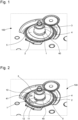
- the invention relates to a device for holding a mobile 2, such as a wheel of a watch movement 100, mounted on a shaft 3.
- the device comprises a clip 1 intended to be mounted on the barrel 4 of the mobile 2 and to cooperate with the shaft 3, between a first and a second position.
- the clip 1 comprises elastic holding means 10, 11 in the form of two arms intended to cooperate with the barrel 4, or with a groove 40 made in this barrel, as well as a locking beak 12 intended to cooperate successively with an opening 41 of the barrel 4 and a groove 30 of the shaft 3 to hold the mobile 2 axially on the shaft 3 in the first position and leave this mobile 2 axially free in the second position, the clip 1 being arranged to be able to move in translation, between the first position, called the locked position, and the second position, called the unlocked or free position in which it can be removed.
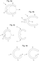
- the clip 1 is in the form of a ring body with two arms 10, 11 with open (or free) ends, each arm being elastically deformable to clamp the groove 40 when the clip 1 is mounted on the barrel 4, the groove 40 extending continuously (or partially) around the circumference of the barrel 4.
- the clip 1 also has a locking beak 12 which is located in the same plane as the plane formed by the two arms 10, 11.
- the clip 1 comprises a locking beak 12 which passes through the opening 41 formed in the barrel 4 and the end of which rests in the groove 30 of the shaft 3 to hold the mobile 2 axially on the shaft 3, the clip 1 thus preventing the mobile 2 from sliding along the shaft 3.
- the locking beak 12 has a length greater than the depth of the opening 41, and slightly less than the distance between the bottom of the groove 30 and the base of the beak 12, to avoid friction between the beak 12 and the shaft 3 and ensure reliable holding of the mobile 2 on the shaft 3.
- the arms 10, 11 of the clip 1 have an internal radius smaller than the radius of the barrel 4 or the groove 40 to obtain elastic deformation of the arms 10, 11 of the clip 1 and ensure its maintenance without play on the barrel 4.
- the clip 1 makes it possible to axially hold elements other than the mobile 2, such as a foil 5 placed on the mobile 2 for example.
- the clip 1 thus makes it possible to axially hold several elements at the same time.
- the clip 1 can be made of a material which is chosen from elastically deformable plastics or metal materials.
- the ring body of the clip 1 has two circular arcs per arm 10, 11.
- Such an arrangement makes it possible to form a stop notch and two positions easily distinguishable by the operator, while making it possible to avoid losing the clip.
- the clip 1 always takes the form of a ring body with two arms 10, 11 with open ends, and one of the ends 10 or 11 of which is curved towards the inside of the clip 1 to form the locking beak 12 arranged to cooperate with the opening 41 of the barrel 4.
- clip 1 as seen on the figure 4d , on the shaft 3 is carried out as follows: firstly, the curved end forming the locking beak is placed in the opening 41 of the barrel 4. The other open end is then passed around the barrel so that the free arm runs along the groove 40 and engages in it until the clip is housed in its locked position.
- the positioning of the clip 1 on the shaft 3 is carried out as follows: firstly, the clip 1 is positioned on the barrel 4, the locking beak being placed opposite the opening 41 and the arms pre-engaged in the groove 40 so that the clip 1 is guided on the barrel 4. Then, the operator pushes the clip 1 into abutment against the barrel 4 to pass the locking beak 12 through the opening 41 into the groove 30 of the shaft 3 and the clip takes its locked position.
- the extraction of clip 1 is done in the opposite direction to that of the installation.
- the inner radii of the arms are not coaxial with the radius of the barrel 4 or the groove 40. This makes it possible to exert a radial stress, directed towards the centre of the barrel, in order to spread the open ends of the arms 10, 11 to facilitate the extraction of the clip.
- the openings 17 can be used in this case to hold the ends of a tool on the clip 1, without the risk of the tool slipping and damaging the movement.
Landscapes
- Physics & Mathematics (AREA)
- General Physics & Mathematics (AREA)
- Engineering & Computer Science (AREA)
- General Engineering & Computer Science (AREA)
- Mechanical Engineering (AREA)
- Clamps And Clips (AREA)
Priority Applications (6)
| Application Number | Priority Date | Filing Date | Title |
|---|---|---|---|
| EP23220359.6A EP4579360A1 (de) | 2023-12-27 | 2023-12-27 | Haltevorrichtung für ein mobiles gerät |
| US18/915,596 US20250215918A1 (en) | 2023-12-27 | 2024-10-15 | Device for retaining a moving part |
| JP2024197138A JP7823994B2 (ja) | 2023-12-27 | 2024-11-12 | 可動部を保持するためのデバイス |
| KR1020240175113A KR20250101856A (ko) | 2023-12-27 | 2024-11-29 | 이동 부품을 보유하기 위한 디바이스 |
| CN202422995058.6U CN223728147U (zh) | 2023-12-27 | 2024-12-05 | 保持装置 |
| CN202411778895.1A CN120215239A (zh) | 2023-12-27 | 2024-12-05 | 运动部件的保持装置 |
Applications Claiming Priority (1)
| Application Number | Priority Date | Filing Date | Title |
|---|---|---|---|
| EP23220359.6A EP4579360A1 (de) | 2023-12-27 | 2023-12-27 | Haltevorrichtung für ein mobiles gerät |
Publications (1)
| Publication Number | Publication Date |
|---|---|
| EP4579360A1 true EP4579360A1 (de) | 2025-07-02 |
Family
ID=89385885
Family Applications (1)
| Application Number | Title | Priority Date | Filing Date |
|---|---|---|---|
| EP23220359.6A Pending EP4579360A1 (de) | 2023-12-27 | 2023-12-27 | Haltevorrichtung für ein mobiles gerät |
Country Status (5)
| Country | Link |
|---|---|
| US (1) | US20250215918A1 (de) |
| EP (1) | EP4579360A1 (de) |
| JP (1) | JP7823994B2 (de) |
| KR (1) | KR20250101856A (de) |
| CN (2) | CN223728147U (de) |
Citations (4)
| Publication number | Priority date | Publication date | Assignee | Title |
|---|---|---|---|---|
| CH594256B5 (de) * | 1973-12-20 | 1977-12-30 | Zenith Time Sa | |
| US5018118A (en) * | 1990-04-16 | 1991-05-21 | Jeanne Ross | Replaceable watch face improvement |
| EP2230572A1 (de) * | 2009-03-17 | 2010-09-22 | Nivarox-FAR S.A. | Radialverschlusssystem für Uhrwerkskomponente |
| CH707590B1 (fr) * | 2013-02-12 | 2017-08-15 | Eta Sa Mft Horlogère Suisse | Roue d'horlogerie antichoc, notamment de centre. |
Family Cites Families (1)
| Publication number | Priority date | Publication date | Assignee | Title |
|---|---|---|---|---|
| JP4554970B2 (ja) * | 2003-08-26 | 2010-09-29 | シチズンホールディングス株式会社 | 時計ムーヴメント |
-
2023
- 2023-12-27 EP EP23220359.6A patent/EP4579360A1/de active Pending
-
2024
- 2024-10-15 US US18/915,596 patent/US20250215918A1/en active Pending
- 2024-11-12 JP JP2024197138A patent/JP7823994B2/ja active Active
- 2024-11-29 KR KR1020240175113A patent/KR20250101856A/ko active Pending
- 2024-12-05 CN CN202422995058.6U patent/CN223728147U/zh active Active
- 2024-12-05 CN CN202411778895.1A patent/CN120215239A/zh active Pending
Patent Citations (4)
| Publication number | Priority date | Publication date | Assignee | Title |
|---|---|---|---|---|
| CH594256B5 (de) * | 1973-12-20 | 1977-12-30 | Zenith Time Sa | |
| US5018118A (en) * | 1990-04-16 | 1991-05-21 | Jeanne Ross | Replaceable watch face improvement |
| EP2230572A1 (de) * | 2009-03-17 | 2010-09-22 | Nivarox-FAR S.A. | Radialverschlusssystem für Uhrwerkskomponente |
| CH707590B1 (fr) * | 2013-02-12 | 2017-08-15 | Eta Sa Mft Horlogère Suisse | Roue d'horlogerie antichoc, notamment de centre. |
Also Published As
| Publication number | Publication date |
|---|---|
| US20250215918A1 (en) | 2025-07-03 |
| CN223728147U (zh) | 2025-12-26 |
| JP7823994B2 (ja) | 2026-03-04 |
| KR20250101856A (ko) | 2025-07-04 |
| CN120215239A (zh) | 2025-06-27 |
| JP2025104258A (ja) | 2025-07-09 |
Similar Documents
| Publication | Publication Date | Title |
|---|---|---|
| EP1921517B1 (de) | Montageelement, das dehnbare Strukturen in Form von Gabeln umfasst, und dieses Element umfassende Uhr | |
| EP3220211B1 (de) | Stosssicherungssystem mit rotationssperre | |
| EP1705533A1 (de) | Zusammenbau eines Teils mit einer Achse | |
| EP3179315B1 (de) | Spiralklötzchenträger mit gesicherter montage | |
| EP0482443A1 (de) | Bremsungsvorrichtung für ein Zahnrad | |
| EP4579360A1 (de) | Haltevorrichtung für ein mobiles gerät | |
| EP2219083A1 (de) | Uhrwerksbestandteil | |
| CH721481A2 (fr) | Dispositif de maintien d'un mobile | |
| EP4160322B1 (de) | Bremsfeder für trägerwelle einer anzeige, uhrwerk mit dieser bremsfeder und einbauverfahren dieser bremsfeder | |
| EP2075652B1 (de) | Antriebs- und Übertragungsorgan für einen Hemmungsmechanimus, damit ausgestattete Platte und Hemmung und mit diesen ausgestattetes Uhrwerk | |
| EP3421925B1 (de) | Drehzapfenverbindungsteil für ein fluggerät oder ein system für fluggerät, insbesondere ein flugkörper | |
| EP4134755A1 (de) | Schlüssel zur befestigung eines zifferblatts auf der platine eines uhrwerks | |
| EP1923754B1 (de) | Mit einem Anzeigemodul ausgerüstetes Uhrwerk | |
| FR2910942A1 (fr) | Dispositif de compensation pour l'assemblage de pieces. | |
| EP3432081A1 (de) | Uhreneinheit | |
| EP4141582A1 (de) | Armbanduhrengehäuse mit einem in einer vordefinierten winkelposition ausgerichteten bodem, armbanduhr mit diesem gehäuse und montageverfahren eines solchen gehäuses | |
| EP4123391B1 (de) | Uhrenkomponente zur befestigung auf einer welle und verfahren | |
| CH698677B1 (fr) | Ensemble comportant un axe et une pièce en silicium fixée audit axe. | |
| EP3432080A1 (de) | Uhrwerksbestandteil | |
| EP3239785B1 (de) | Haltevorrichtung eines mobilgeräts | |
| EP4280002A1 (de) | Chronographenmodul mit einem abnehmbaren rad | |
| EP4575657A1 (de) | Vorrichtung zur zeiteinstellung einer uhrwerke | |
| EP4123394A1 (de) | Ring zur mechanischen verbindung von zwei uhrenkomponenten | |
| EP3779607A1 (de) | Durchführungsverfahren eines zusammenbaus einer einheit aus elastischem halterungsorgan, und uhrwerkskomponente mit einem halterungselement | |
| EP3742236B1 (de) | Uhrvorrichtung, die eine erste komponente umfasst, die auf einer zweiten komponente durch plastische verformung fixiert ist |
Legal Events
| Date | Code | Title | Description |
|---|---|---|---|
| PUAI | Public reference made under article 153(3) epc to a published international application that has entered the european phase |
Free format text: ORIGINAL CODE: 0009012 |
|
| STAA | Information on the status of an ep patent application or granted ep patent |
Free format text: STATUS: THE APPLICATION HAS BEEN PUBLISHED |
|
| AK | Designated contracting states |
Kind code of ref document: A1 Designated state(s): AL AT BE BG CH CY CZ DE DK EE ES FI FR GB GR HR HU IE IS IT LI LT LU LV MC ME MK MT NL NO PL PT RO RS SE SI SK SM TR |
|
| P01 | Opt-out of the competence of the unified patent court (upc) registered |
Free format text: CASE NUMBER: APP_31979/2025 Effective date: 20250702 |
|
| STAA | Information on the status of an ep patent application or granted ep patent |
Free format text: STATUS: REQUEST FOR EXAMINATION WAS MADE |
|
| 17P | Request for examination filed |
Effective date: 20251223 |