EP4579283A2 - Mobile robotervorrichtung und verfahren zur steuerung der mobilen robotervorrichtung - Google Patents
Mobile robotervorrichtung und verfahren zur steuerung der mobilen robotervorrichtung Download PDFInfo
- Publication number
- EP4579283A2 EP4579283A2 EP25176499.9A EP25176499A EP4579283A2 EP 4579283 A2 EP4579283 A2 EP 4579283A2 EP 25176499 A EP25176499 A EP 25176499A EP 4579283 A2 EP4579283 A2 EP 4579283A2
- Authority
- EP
- European Patent Office
- Prior art keywords
- charging station
- distance
- mobile robot
- robot
- robot device
- Prior art date
- Legal status (The legal status is an assumption and is not a legal conclusion. Google has not performed a legal analysis and makes no representation as to the accuracy of the status listed.)
- Pending
Links
Images


Classifications
-
- B—PERFORMING OPERATIONS; TRANSPORTING
- B25—HAND TOOLS; PORTABLE POWER-DRIVEN TOOLS; MANIPULATORS
- B25J—MANIPULATORS; CHAMBERS PROVIDED WITH MANIPULATION DEVICES
- B25J11/00—Manipulators not otherwise provided for
-
- A—HUMAN NECESSITIES
- A47—FURNITURE; DOMESTIC ARTICLES OR APPLIANCES; COFFEE MILLS; SPICE MILLS; SUCTION CLEANERS IN GENERAL
- A47L—DOMESTIC WASHING OR CLEANING; SUCTION CLEANERS IN GENERAL
- A47L11/00—Machines for cleaning floors, carpets, furniture, walls, or wall coverings
- A47L11/40—Parts or details of machines not provided for in groups A47L11/02 - A47L11/38, or not restricted to one of these groups, e.g. handles, arrangements of switches, skirts, buffers, levers
- A47L11/4011—Regulation of the cleaning machine by electric means; Control systems and remote control systems therefor
-
- A—HUMAN NECESSITIES
- A47—FURNITURE; DOMESTIC ARTICLES OR APPLIANCES; COFFEE MILLS; SPICE MILLS; SUCTION CLEANERS IN GENERAL
- A47L—DOMESTIC WASHING OR CLEANING; SUCTION CLEANERS IN GENERAL
- A47L9/00—Details or accessories of suction cleaners, e.g. mechanical means for controlling the suction or for effecting pulsating action; Storing devices specially adapted to suction cleaners or parts thereof; Carrying-vehicles specially adapted for suction cleaners
- A47L9/28—Installation of the electric equipment, e.g. adaptation or attachment to the suction cleaner; Controlling suction cleaners by electric means
- A47L9/2805—Parameters or conditions being sensed
-
- A—HUMAN NECESSITIES
- A47—FURNITURE; DOMESTIC ARTICLES OR APPLIANCES; COFFEE MILLS; SPICE MILLS; SUCTION CLEANERS IN GENERAL
- A47L—DOMESTIC WASHING OR CLEANING; SUCTION CLEANERS IN GENERAL
- A47L9/00—Details or accessories of suction cleaners, e.g. mechanical means for controlling the suction or for effecting pulsating action; Storing devices specially adapted to suction cleaners or parts thereof; Carrying-vehicles specially adapted for suction cleaners
- A47L9/28—Installation of the electric equipment, e.g. adaptation or attachment to the suction cleaner; Controlling suction cleaners by electric means
- A47L9/2836—Installation of the electric equipment, e.g. adaptation or attachment to the suction cleaner; Controlling suction cleaners by electric means characterised by the parts which are controlled
- A47L9/2852—Elements for displacement of the vacuum cleaner or the accessories therefor, e.g. wheels, casters or nozzles
-
- B—PERFORMING OPERATIONS; TRANSPORTING
- B25—HAND TOOLS; PORTABLE POWER-DRIVEN TOOLS; MANIPULATORS
- B25J—MANIPULATORS; CHAMBERS PROVIDED WITH MANIPULATION DEVICES
- B25J13/00—Controls for manipulators
- B25J13/08—Controls for manipulators by means of sensing devices, e.g. viewing or touching devices
- B25J13/088—Controls for manipulators by means of sensing devices, e.g. viewing or touching devices with position, velocity or acceleration sensors
- B25J13/089—Determining the position of the robot with reference to its environment
-
- B—PERFORMING OPERATIONS; TRANSPORTING
- B25—HAND TOOLS; PORTABLE POWER-DRIVEN TOOLS; MANIPULATORS
- B25J—MANIPULATORS; CHAMBERS PROVIDED WITH MANIPULATION DEVICES
- B25J19/00—Accessories fitted to manipulators, e.g. for monitoring, for viewing; Safety devices combined with or specially adapted for use in connection with manipulators
- B25J19/005—Accessories fitted to manipulators, e.g. for monitoring, for viewing; Safety devices combined with or specially adapted for use in connection with manipulators using batteries, e.g. as a back-up power source
-
- B—PERFORMING OPERATIONS; TRANSPORTING
- B25—HAND TOOLS; PORTABLE POWER-DRIVEN TOOLS; MANIPULATORS
- B25J—MANIPULATORS; CHAMBERS PROVIDED WITH MANIPULATION DEVICES
- B25J19/00—Accessories fitted to manipulators, e.g. for monitoring, for viewing; Safety devices combined with or specially adapted for use in connection with manipulators
- B25J19/02—Sensing devices
- B25J19/021—Optical sensing devices
- B25J19/022—Optical sensing devices using lasers
-
- B—PERFORMING OPERATIONS; TRANSPORTING
- B25—HAND TOOLS; PORTABLE POWER-DRIVEN TOOLS; MANIPULATORS
- B25J—MANIPULATORS; CHAMBERS PROVIDED WITH MANIPULATION DEVICES
- B25J5/00—Manipulators mounted on wheels or on carriages
-
- B—PERFORMING OPERATIONS; TRANSPORTING
- B25—HAND TOOLS; PORTABLE POWER-DRIVEN TOOLS; MANIPULATORS
- B25J—MANIPULATORS; CHAMBERS PROVIDED WITH MANIPULATION DEVICES
- B25J9/00—Programme-controlled manipulators
- B25J9/16—Programme controls
- B25J9/1602—Programme controls characterised by the control system, structure, architecture
- B25J9/161—Hardware, e.g. neural networks, fuzzy logic, interfaces, processor
-
- B—PERFORMING OPERATIONS; TRANSPORTING
- B25—HAND TOOLS; PORTABLE POWER-DRIVEN TOOLS; MANIPULATORS
- B25J—MANIPULATORS; CHAMBERS PROVIDED WITH MANIPULATION DEVICES
- B25J9/00—Programme-controlled manipulators
- B25J9/16—Programme controls
- B25J9/1656—Programme controls characterised by programming, planning systems for manipulators
- B25J9/1664—Programme controls characterised by programming, planning systems for manipulators characterised by motion, path, trajectory planning
-
- B—PERFORMING OPERATIONS; TRANSPORTING
- B25—HAND TOOLS; PORTABLE POWER-DRIVEN TOOLS; MANIPULATORS
- B25J—MANIPULATORS; CHAMBERS PROVIDED WITH MANIPULATION DEVICES
- B25J9/00—Programme-controlled manipulators
- B25J9/16—Programme controls
- B25J9/1694—Programme controls characterised by use of sensors other than normal servo-feedback from position, speed or acceleration sensors, perception control, multi-sensor controlled systems, sensor fusion
- B25J9/1697—Vision controlled systems
-
- G—PHYSICS
- G01—MEASURING; TESTING
- G01S—RADIO DIRECTION-FINDING; RADIO NAVIGATION; DETERMINING DISTANCE OR VELOCITY BY USE OF RADIO WAVES; LOCATING OR PRESENCE-DETECTING BY USE OF THE REFLECTION OR RERADIATION OF RADIO WAVES; ANALOGOUS ARRANGEMENTS USING OTHER WAVES
- G01S17/00—Systems using the reflection or reradiation of electromagnetic waves other than radio waves, e.g. lidar systems
- G01S17/02—Systems using the reflection of electromagnetic waves other than radio waves
- G01S17/06—Systems determining position data of a target
- G01S17/08—Systems determining position data of a target for measuring distance only
- G01S17/10—Systems determining position data of a target for measuring distance only using transmission of interrupted, pulse-modulated waves
-
- G—PHYSICS
- G01—MEASURING; TESTING
- G01S—RADIO DIRECTION-FINDING; RADIO NAVIGATION; DETERMINING DISTANCE OR VELOCITY BY USE OF RADIO WAVES; LOCATING OR PRESENCE-DETECTING BY USE OF THE REFLECTION OR RERADIATION OF RADIO WAVES; ANALOGOUS ARRANGEMENTS USING OTHER WAVES
- G01S17/00—Systems using the reflection or reradiation of electromagnetic waves other than radio waves, e.g. lidar systems
- G01S17/02—Systems using the reflection of electromagnetic waves other than radio waves
- G01S17/06—Systems determining position data of a target
- G01S17/42—Simultaneous measurement of distance and other co-ordinates
-
- G—PHYSICS
- G01—MEASURING; TESTING
- G01S—RADIO DIRECTION-FINDING; RADIO NAVIGATION; DETERMINING DISTANCE OR VELOCITY BY USE OF RADIO WAVES; LOCATING OR PRESENCE-DETECTING BY USE OF THE REFLECTION OR RERADIATION OF RADIO WAVES; ANALOGOUS ARRANGEMENTS USING OTHER WAVES
- G01S17/00—Systems using the reflection or reradiation of electromagnetic waves other than radio waves, e.g. lidar systems
- G01S17/88—Lidar systems specially adapted for specific applications
- G01S17/89—Lidar systems specially adapted for specific applications for mapping or imaging
-
- G—PHYSICS
- G05—CONTROLLING; REGULATING
- G05D—SYSTEMS FOR CONTROLLING OR REGULATING NON-ELECTRIC VARIABLES
- G05D1/00—Control of position, course, altitude or attitude of land, water, air or space vehicles, e.g. using automatic pilots
- G05D1/02—Control of position or course in two dimensions
- G05D1/021—Control of position or course in two dimensions specially adapted to land vehicles
- G05D1/0212—Control of position or course in two dimensions specially adapted to land vehicles with means for defining a desired trajectory
- G05D1/0225—Control of position or course in two dimensions specially adapted to land vehicles with means for defining a desired trajectory involving docking at a fixed facility, e.g. base station or loading bay
-
- G—PHYSICS
- G05—CONTROLLING; REGULATING
- G05D—SYSTEMS FOR CONTROLLING OR REGULATING NON-ELECTRIC VARIABLES
- G05D1/00—Control of position, course, altitude or attitude of land, water, air or space vehicles, e.g. using automatic pilots
- G05D1/02—Control of position or course in two dimensions
- G05D1/021—Control of position or course in two dimensions specially adapted to land vehicles
- G05D1/0231—Control of position or course in two dimensions specially adapted to land vehicles using optical position detecting means
- G05D1/0238—Control of position or course in two dimensions specially adapted to land vehicles using optical position detecting means using obstacle or wall sensors
- G05D1/024—Control of position or course in two dimensions specially adapted to land vehicles using optical position detecting means using obstacle or wall sensors in combination with a laser
-
- A—HUMAN NECESSITIES
- A47—FURNITURE; DOMESTIC ARTICLES OR APPLIANCES; COFFEE MILLS; SPICE MILLS; SUCTION CLEANERS IN GENERAL
- A47L—DOMESTIC WASHING OR CLEANING; SUCTION CLEANERS IN GENERAL
- A47L2201/00—Robotic cleaning machines, i.e. with automatic control of the travelling movement or the cleaning operation
- A47L2201/02—Docking stations; Docking operations
- A47L2201/022—Recharging of batteries
Definitions
- the disclosure relates to a mobile robot device and, more particularly to a mobile robot device that changes a scanning frequency of a LiDAR sensor based on a distance to a charging station.
- a mobile robot device is recharged through a wired charging system.
- high current may be necessary to rapidly charge the mobile robot device in a wired manner.
- transmission power increases in accordance with the increase in current, there may be a heat generation problem on a power receiver of the mobile robot device.
- a mobile robot device including a driving unit configured to control movement of the mobile robot device, a memory, a light detection and ranging (LiDAR) sensor configured to emit first light of a first frequency and second light of a second frequency that is less than the first frequency, and a processor configured to obtain a first position of the mobile robot device relative to a charging station based on scanning a surrounding environment of the mobile robot device by the LiDAR sensor emitting the first light, control the driving unit to move the mobile robot device towards the charging station based on the first position of the mobile robot device relative to the charging station, identify whether a distance from the mobile robot device to the charging station is within a first distance, based on the distance from the mobile robot device to the charging station being within the first distance, obtain a second position of the mobile robot device relative to the charging station based on scanning the surrounding environment of the mobile robot device by the LiDAR sensor emitting the second light, and control the driving unit to move the mobile robot device towards the charging station based on the second
- the first distance may be stored in the memory.
- the processor may be configured to based on the second frequency being a minimum frequency of the LiDAR sensor and the distance from the mobile robot device to the charging station being within a second distance that is less than the distance from the mobile robot device to the charging station via the LiDAR sensor that uses the second frequency, predict a third position of the mobile robot device relative to the charging station based on a pattern of a point cloud corresponding to the charging station obtained via the LiDAR sensor and a pattern stored in the memory.
- a method for controlling a mobile robot device including a LiDAR sensor and a driving unit, the method including obtaining a first position of the mobile robot device relative to a charging station based on scanning a surrounding environment of the mobile robot device by the LiDAR sensor emitting first light of a first frequency, moving the mobile robot device towards the charging station based on the first position of the mobile robot device relative to the charging station, identifying whether a distance from the mobile robot device to the charging station is within a first distance, based on the distance from the mobile robot device to the charging station being within the first distance, obtaining a second position of the mobile robot device relative to the charging station based on scanning the surrounding environment of the mobile robot device by the LiDAR sensor emitting a second light of a second frequency less than the first frequency, and moving the mobile robot device towards the charging station based on the second position of the mobile robot device relative to the charging station.
- the controlling may comprise based on a frequency of the LiDAR sensor being changed from the first frequency to the second frequency, obtaining the second position of the mobile robot device relative to the charging station via the LiDAR sensor emitting the second light and controlling the driving unit to move the mobile robot device towards the charging station based on the second position of the mobile robot device relative to the charging station.
- the method may further comprise based on the distance from the mobile robot device to the charging station being within a second distance less than the first distance, controlling the LiDAR sensor to scan the surrounding environment of the mobile robot device by changing the frequency of the LiDAR sensor to a third frequency that is less than the second frequency.
- first,” “second,” and the like used in the disclosure may denote various elements, regardless of order and/or importance, and may be used to distinguish one element from another, and does not limit the elements.
- a first user device and a second user device may represent user devices different from each other, regardless of order and/or importance.
- a first element may be referred to as a second element and the second element may also be similarly referred to as the first element, while not departing from the scope of a right of the disclosure.
- a certain element e.g., first element
- another element e.g., second element
- the certain element may be connected to the other element directly or through still another element (e.g., third element).
- a certain element e.g., first element
- another element e.g., second element
- there is no element e.g., third element
- the mobile robot device 100 may identify whether the distance to the charging station 200 is within a first distance 10 by various methods while moving to the charging station 200.
- the first distance may be a reference distance for the mobile robot device 100 to determine whether to change a frequency of the LiDAR sensor 110.
- the mobile robot device 100 may identify whether the distance to the charging station 200 is within the first distance based on information regarding the prestored first distance.
- the information regarding the first distance for the mobile robot device 100 may be utilized to determine whether to change the frequency of the LiDAR sensor 110, and such information may be stored in advance in a memory 130 of the mobile robot device 100.
- the information regarding the prestored first distance stored may be a setting of the mobile robot device 100 changed by a user.
- the mobile robot device 100 may obtain a distance to the charging station 200 via the LiDAR sensor 110.
- the mobile robot device 100 may identify whether the distance to the charging station 200 is currently within the first distance through the information regarding the prestored first distance.
- the mobile robot device 100 may store information regarding a plurality of predetermined distances for determining whether to additionally change the frequency (e.g., information regarding second and third distances, and the like), in addition to the information regarding the first distance to the charging station 200. Accordingly, the mobile robot device 100 may identify when the mobile robot device 100 approaches within the various distances to the charging station 200, among the plurality of predetermined distances, based on the information regarding the predetermined distances.
- the information regarding the plurality of predetermined distances will be described in detail with references to FIGS. 3A to 3C .
- the mobile robot device 100 may obtain a similarity value between a pattern of the point cloud corresponding to the charging station obtained via the LiDAR sensor 110 and a predetermined pattern. Specifically, the mobile robot device 100 may store a pattern of the point cloud (e.g., the number of points, shape formed of point cloud, and the like) corresponding to the charging station 200 in the memory 130. The mobile robot device 100 may obtain a value of similarity between both patterns by comparing the pattern of the obtained point cloud corresponding to the charging station with the point cloud corresponding to the charging station 200 stored in memory 130.
- a pattern of the point cloud e.g., the number of points, shape formed of point cloud, and the like
- the mobile robot device 100 may identify whether the obtained similarity value exceeds a threshold value.
- the threshold value may be a predetermined value and may be modified as a setting by a user.
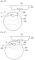
- the mobile robot device 100 may identify that the distance to the charging station 200 is within the first distance 10. For example, as illustrated in FIG. 1A , since a part of the charging station 200 is included in the circle having the shortest measurable distance r1 of the LiDAR sensor 110 as a radius, the mobile robot device 100 may not obtain the point cloud corresponding to the entire charging station 200.
- the mobile robot device 100 may move to the charging station 200 based on the first position relative to the charging station. For example, when a part of the charging station 200 is not included in the shortest measurable distance circle 20-1 of the LiDAR sensor 110 that uses the first frequency, the mobile robot device 100 may obtain the point cloud corresponding to the entire charging station 200 via the LiDAR sensor 110. Accordingly, the mobile robot device 100 may obtain the similarity value equal to or greater than the threshold value, when calculating the similarity value between the pattern of the obtained point cloud and the predetermined pattern. At this time, the mobile robot device 100 may identify that the current distance to the charging station 200 is not within the first distance and continuously move to the charging station based on the obtained first position relative to the charging station.
- the mobile robot device 100 may identify a magnitude of the second frequency based on a distance measurable by the LiDAR sensor 110 using the first frequency and a distance the mobile robot device 100 has traveled. The embodiment of determining the second frequency based on the distance the mobile robot device 100 has traveled will be described in detail with reference to FIGS. 3A and 3B .
- the mobile robot device 100 may obtain a second position relative to the charging station 200 via the LiDAR sensor that uses the second frequency. For example, as illustrated in FIG. 1B , since the shortest measurable distance of the LiDAR sensor 110 is decreased from r1 to r2 along with a decrease in frequency, the mobile robot device 100 may obtain information regarding a distance to and a position of the charging station 200 via the LiDAR sensor 110 based on the current position. The mobile robot device 100 may move to the charging station 200 based on the obtained relative second position.
- the mobile robot device 100 may identify whether to additionally move the mobile robot device 100 to a docking point of the charging station 200 based on an amount of charged power received from the charging station 200.
- the embodiment of additionally moving the mobile robot device 100 based on the amount of the charged power will be described in detail with reference to FIGS. 5A and 5B .
- FIG. 2A is a block diagram schematically illustrating a configuration of the mobile robot device 100 according to an embodiment.
- the mobile robot device 100 may include the LiDAR sensor 110, a driving unit 120, a memory 130, and a processor 140.
- the configuration illustrated in FIG. 2A is an exemplary diagram for implementing the embodiment of the disclosure, and suitable hardware and software configurations that are apparent to those skilled in the art may be additionally included in the mobile robot device 100.
- the driving unit 120 may be an element capable of conveying the mobile robot device 100 under the control of the processor 140 and may include a motor and a plurality of wheels driven by the motor. Specifically, the driving unit 120 may change a movement direction or a movement speed of the mobile robot device 100 under the control of the processor 140.
- the memory 130 may store the point cloud corresponding to the charging station 200 in advance.
- the memory 130 may store the point cloud corresponding to an object (e.g., charging station 200) around the mobile robot device 100 obtained via the LiDAR sensor 110.
- the processor 140 may control the driving unit 120 so that the mobile robot device 100 moves to the charging station 200 based on the obtained first position relative to the charging station 200. For example, the processor 140 may identify a direction and a shortest straight line distance from the mobile robot device 100 to the docking point 210 of the charging station 200 based on the relative first position. The processor 140 may control the driving unit 120 to move in the direction to the docking point 210 of the charging station 200 by the identified distance.
- the processor 140 may identify whether the distance to the charging station 200 is within the first distance while the mobile robot device 100 moves.
- the processor 140 may identify whether the distance to the charging station 200 is within the first distance based on the information regarding the first distance stored in the memory 130. Specifically, the processor 140 may identify the current distance between the mobile robot device 100 and the charging station 200 via the LiDAR sensor 110 while the mobile robot device 100 moves. In addition, the processor 140 may identify whether the distance between the mobile robot device 100 that is moving and the charging station 200 is within the first distance based on the information regarding the first distance stored in the memory 130. In the same manner, the processor 140 may identify whether the distance to the charging station is within the second and third distances based on the information regarding the predetermined distance stored in the memory 130.
- the processor 140 may identify whether the distance to the charging station 200 is within the first distance based on the pattern of the point cloud corresponding to the charging station 200 obtained via the LiDAR sensor 110. Specifically, the processor 140 may obtain the similarity value between the pattern of the point cloud corresponding to the charging station 200 obtained via the LiDAR sensor 110 and the pattern stored in the memory 130. For example, the processor 140 may obtain the value showing the similarity by comparing the pattern of the point cloud (e.g., the number of points and the shape formed of the point cloud) corresponding to the charging station 200 obtained via the LiDAR sensor 110 with the pattern stored in memory 130.
- the pattern of the point cloud e.g., the number of points and the shape formed of the point cloud
- the processor 140 may identify whether the obtained similarity value exceeds the threshold value. When the similarity value is identified to be less than the threshold value, the processor 140 may identify that the distance to the charging station 200 is within the first distance. On the other hand, when the similarity value is identified to be equal to or greater than the threshold value, the processor 140 may control the driving unit 120 so that the mobile robot device 100 moves to the charging station 200 based on the obtained first position relative to the charging station 200.
- the processor 140 may control the LiDAR sensor 110 to scan the surroundings of the mobile robot device 100 by changing the frequency of the LiDAR sensor 110 to the second frequency less than the first frequency.
- the frequency of the LiDAR sensor 110 is decreased, the shortest measurable distance decreases. Accordingly, when the distance to the charging station 200 is identified to be within the first distance, the processor 140 may accurately obtain the information regarding the distance and the direction to the charging station 200 via the LiDAR sensor 110 by changing the frequency to the second frequency less than the first frequency.
- the processor 140 may identify a magnitude of the second frequency based on the distance measurable by the LiDAR sensor 110 using the first frequency and the distance the mobile robot device 100 has moved. Specifically, the processor 140 may obtain the distance the mobile robot device 100 has moved from when the first position relative to the charging station 200 is obtained until when the distance to the charging station 200 is identified to be within the first distance via the LiDAR sensor 110. The processor 140 may calculate a current distance between the mobile robot device 100 and the docking point 210 of the charging station 200 based on the distance the mobile robot device 100 has moved.
- the processor 140 may predict a region of the docking point 210 that may be included in the minimum measurable circle of the LiDAR sensor 110 that uses the first frequency, while the mobile robot device 100 moves from the current position to a position separated from the docking point 210 of the charging station 200 by a threshold distance.
- the processor 140 may calculate and identify the second frequency of the LiDAR sensor 110 so that the docking point 210 is not included within the minimum measurable distance circle, when the mobile robot device 100 is at a position separated from the docking point 210 by a threshold distance, based on the predicted region of the docking point 210.
- the processor 140 may control the LiDAR sensor 110 to change the frequency of the LiDAR sensor 110 from the first frequency to the identified second frequency.
- the processor 140 may control the LiDAR sensor 110 to change the frequency of the LiDAR sensor 110 to the minimum frequency from among the variable frequencies.
- the processor 140 may control the LiDAR sensor 110 to change the frequency of the LiDAR sensor 110 from the first frequency to the second frequency by a predetermined value.
- the predetermined value may vary depending on a size and a type of the mobile robot device 100 and may also be changed according to a setting of the mobile robot device 100 by a user.
- the processor 140 may obtain the second position relative to the charging station 200 via the LiDAR sensor 110 that uses the second frequency.
- the processor 140 may control the driving unit 120 to move the mobile robot device 100 to the charging station 200 based on the second position relative to the charging station 200.
- the processor 140 may control the LiDAR sensor 110 to scan the surroundings of the mobile robot device 100 by changing the frequency of the LiDAR sensor 110 to a third frequency less than the second frequency.
- the processor 140 may identify whether the distance to the charging station 200 is within the second distance based on the information regarding the second distance stored in the memory 130. Specifically, the processor 140 may identify whether the distance to the charging station 200 obtained via the LiDAR sensor 110 is within the second distance stored in memory 130. The information regarding the second distance stored in memory 130 may be changed by a user input that changes the setting of the mobile robot device 100.
- the processor 140 may identify whether the distance to the charging station 200 is within the second distance based on the point cloud corresponding to the charging station 200 obtained via the LiDAR sensor 110 that uses the second frequency. Specifically, when the similarity value between the pattern of the point cloud corresponding to the charging station obtained via the LiDAR sensor 110 that uses the second frequency and the pattern of the point cloud stored in advance exceeds a threshold value, the processor 140 may identify that the distance to the charging station 200 is within the second distance.
- the specific configuration is similar to the processor 140 identifying whether the distance to the charging station 200 is within the first distance, and therefore a redundant description will not be repeated.
- the process of determining the third frequency by the processor 140 is also similar to the process of determining the second frequency, and therefore a redundant description will not be repeated.
- the processor 140 may identify whether to adjust the mobile robot device 100 to the docking point of the charging station based on the amount of charged power received from the charging station 200. Specifically, when the amount of charged power received from the charging station 200 is less than a predetermined value, the processor 140 may identify to additionally move the mobile robot device 100. Then, the processor 140 may obtain a position relative to the docking point of the charging station via the LiDAR sensor 110 and control the driving unit 120 to move to the docking point of the charging station 200 based on the obtained position. When the accurate docking between the mobile robot device 100 and the charging station 200 is not accomplished, the charging efficiency may decrease and a transmission resonator of the mobile robot device 100 may be overheated. Accordingly, the processor 140 may obtain the position relative to the charging station 200 via the LiDAR sensor 110 and control the driving unit 120 to additionally move the mobile robot device 100 to the charging station 200 based on the relative position, in order to perform more accurate docking.
- the processor 140 may stop the movement of the mobile robot device 100 and receive the power from the charging station 200.
- the processor 140 may predict the third position relative to the charging station 200 based on the pattern of the point cloud corresponding to the charging station 200 obtained via the LiDAR sensor 110 and the pattern stored in memory 130. For example, when the similarity value between the pattern of the point cloud corresponding to the charging station 200 obtained via the LiDAR sensor 110 that uses the second frequency and the pattern stored in advance is identified to be less than a threshold value, the processor 140 may control the LiDAR sensor 110 to decrease the frequency of the LiDAR sensor 110 to the third frequency less than the second frequency.
- the processor 140 may not further decrease the frequency of the LiDAR sensor 110. Accordingly, the processor 140 may predict the current distance and direction to the charging station 200 by comparing the pattern of the obtained point cloud corresponding to the charging station 200 obtained before the distance to the charging station 200 is identified to be within the second distance with the pattern stored in memory 130. The processor 140 may control the driving unit 120 to move the mobile robot device 100 to the charging station 200 based on the predicted distance and direction.
- the processor 140 may include one or more of a central processing unit (CPU), a microcontroller unit (MCU), a microprocessing unit (MPU), a controller, an application processor (AP), or a communication processor (CP), and an ARM processor or may be defined as the corresponding term.
- the processor 140 may be implemented as System on Chip (SoC) or large scale integration (LSI) including the processing algorithm or may be implemented in form of a Field Programmable gate array (FPGA).
- SoC System on Chip
- LSI large scale integration
- FPGA Field Programmable gate array
- the processor 140 may perform various functions by executing computer executable instructions stored in the memory 130.
- FIG. 2B is a block diagram illustrating a configuration of the mobile robot device 100 according to an embodiment.
- the mobile robot device 100 may include the LiDAR sensor 110, the driving unit 120, the memory 130, the processor 140, a communicator 150, a display 160, a battery 170, an input unit 180, a speaker 190, and a distance sensor 195.
- the LiDAR sensor 110, the driving unit 120, the memory 130, and the processor 140 have been described with reference to FIG. 2A and therefore redundant descriptions thereof will not be repeated.
- the communicator 150 may perform communication with an external device and an external server via various wired or wireless communication methods.
- the communication connection of the communicator 150 with the external device and the external server may include networked communication via a third device (e.g., a repeater, a hub, an access point, a gateway, or the like).
- a third device e.g., a repeater, a hub, an access point, a gateway, or the like.
- the communicator 150 may include various communication modules to communicate with the external device.
- the communicator 150 may include wireless communication modules and, for example, include a cellular communication module using at least one of LTE, LTE Advance (LTE-A), code division multiple access (CDMA), wideband CDMA (WCDMA), universal mobile telecommunications system (UMTS), Wireless Broadband (WiBro), or global system for mobile communications (GSM).
- the wireless communication module may, for example, include at least one of wireless fidelity (Wi-Fi), Bluetooth, Bluetooth Low Energy (BLE), and Zigbee.
- the communicator 150 may perform wired or wireless communication through connection with the charging station 200 when docked.
- the display 160 may display various pieces of information under the control of the processor 140.
- the display 160 may display the pattern of the point cloud corresponding to the charging station 200 obtained via the LiDAR sensor 110 under the control of the processor 140.
- the display 160 may display a user interface (UI) for receiving user input to change settings or control the mobile robot device 100, for example changing the predetermined distance information to the charging station 200 under the control of the processor 140.
- UI user interface
- the display 160 may also be implemented as a touch screen together with a touch panel. There is no limitation to the above implementation, and the display 160 may be variously implemented.
- the battery 170 is an element for supplying power of the mobile robot device 100 and the battery 170 may be charged by the charging station 200.
- the battery 170 may include a reception resonator for wireless charging. Accordingly, the reception resonator of the battery 170 may receive the power from the transmission resonator of the charging station 200.
- the battery 170 may transmit the information regarding the amount of power received from the charging station 200 to the processor 140.
- a charging method of the battery 170 may be a constant current constant voltage (CCCV) charging method for rapidly charging a predetermined amount through a constant current (CC) charging method and charging the remaining amount through a constant voltage (CV) method and any inductive charging scheme, but the charging method is not limited thereto, and the battery 170 may be charged by various methods.
- CCCV constant current constant voltage
- the input unit 180 may receive various user inputs and tranmsit the user inputs to the processor 140.
- the input unit 180 may include a touch sensor, a (digital) pen sensor, a pressure sensor, and a key.
- the touch sensor may use, for example, at least one type of an electrostatic type, a pressure-sensitive type, an infrared type, or an ultrasonic type.
- the input unit 180 may be incorporated into the display 160 as a touch sensitive display.
- the input unit 180 may receive a signal including the user command and transmit the signal to the processor 140.
- the distance sensor 195 is an additional element for obtaining the distance information between the mobile robot device 100 and the charging station 200 excluding the LiDAR sensor 110 and may include an infrared ray sensor, an ultrasonic sensor, a radio frequency (RF) sensor, and the like. Accordingly, the processor 140 may obtain the distance information to the charging station 200 via various distance sensors 195, in addition to the LiDAR sensor 110.
- the LiDAR sensor 110 may include an infrared ray sensor, an ultrasonic sensor, a radio frequency (RF) sensor, and the like.
- RF radio frequency
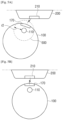
- FIGS. 3A to 3C are views for illustrating a process in that the mobile robot device 100 decreases the frequency of the LiDAR sensor 110 according to an embodiment.
- the mobile robot device 100 may obtain the first position relative to the charging station 200 (or the docking point 210 of the charging station 200) via the LiDAR sensor 110 that uses the first frequency. Specifically, the mobile robot device 100 may obtain the information regarding the direction and the distance to the charging station 200 based on the current position via the LiDAR sensor 110. For example, as illustrated in FIG. 3A , the information regarding the distance and the direction to the charging station 200 obtained by the mobile robot device 100 may be information regarding the distance and the direction of a shortest straight line 320 between the mobile robot device 100 and the docking point 210 of the charging station 200. The mobile robot device 100 may move to the charging station 200 based on the obtained information regarding the distance and the direction to the charging station 200.
- the mobile robot device 100 may identify whether the distance to the charging station 200 is within the first distance while moving to the charging station 200.
- the mobile robot device 100 may identify whether the distance to the charging station 200 is within the first distance based on the information regarding the first distance stored in memory 130. For example, the mobile robot device 100 may store information indicating that a straight line 330 illustrated in FIG. 3B or a distance within a threshold error range is the first distance, in memory 130. When the distance to the charging station 200 obtained via the LiDAR sensor 110 is identified as the distance of the straight line 330 illustrated in FIG. 3B or the distance in the threshold error range, the mobile robot device 100 may identify that the distance to the charging station 200 is within the first distance.
- the mobile robot device 100 may identify that the distance to the charging station 200 is within the first distance based on the point cloud corresponding to the charging station 200 obtained via the LiDAR sensor 110 that uses the first frequency. As illustrated in FIG. 3B , the shortest measurable distance of the LiDAR sensor 110 that uses the first frequency is r1 and a part of the charging station 200 is included in a minimum measurable circle 310 having r1 as a radius. Accordingly, the mobile robot device 100 may not obtain the point cloud corresponding to the entire charging station 200 via the LiDAR sensor 110 that uses the first frequency.
- the mobile robot device 100 may obtain the similarity value between the pattern of the obtained point cloud corresponding to the charging station 200 and the predetermined pattern and identify whether the obtained similarity value is greater than the threshold value. As illustrated in FIG. 3B , since the mobile robot device 100 did not obtain the point cloud corresponding to the entire charging station 200, the mobile robot device 100 may identify that the similarity value obtained by comparing the pattern of the point cloud with the predetermined pattern to be less than the threshold value. When the similarity value is identified to be less than the threshold value, the mobile robot device 100 may identify that the distance to the charging station 200 is within the first distance 320.
- the mobile robot device 100 may change the frequency of the LiDAR sensor 110 to the second frequency less than the first frequency. As illustrated in FIG. 3B , when the frequency of the LiDAR sensor 110 decreases to the second frequency, the shortest measurable distance of the LiDAR sensor 110 decreases from r1 to r2. Accordingly, a part of the charging station 200 may not be included in a minimum measurable circle 340 according to the second frequency having r2 as a radius. Therefore, the mobile robot device 100 may more accurately grasp the information regarding the direction and the distance to the charging station 200 by decreasing the frequency of the LiDAR sensor 110.
- the mobile robot device 100 may obtain the distance the mobile robot device 100 has moved through the distance of the straight line 320 when the first position relative to the charging station 200 is obtained and the distance when the distance to the charging station is identified to be within the first distance 320.
- the mobile robot device 100 may obtain the distance from the current position of the mobile robot device 100 to the docking point 210 of the charging station 200 based on the distance the mobile robot device 100 has moved.
- the mobile robot device 100 may predict a region of the docking point 210 that may be included in the minimum measurable circle of the LiDAR sensor 110 that uses the first frequency while the mobile robot device 10 moves from the current position to a position separated from the docking point 210 of the charging station 200 by a threshold distance.
- the mobile robot device 100 may calculate and identify the second frequency of the LiDAR sensor 110 so that the docking point 210 is not included within the minimum measurable distance circle, when the mobile robot device 100 is at a position separated from the docking point 210 by a threshold distance, based on the predicted region of the docking point 210.
- the mobile robot device 100 may identify the frequency of the LiDAR sensor 110 as the minimum frequency among the variable frequencies capable of being emitted by the LiDAR sensor 110.
- the mobile robot device 100 may obtain the second position relative to the charging station 200 (or docking point 210 of the charging station 200) via the LiDAR sensor 110 that uses the second frequency.
- the mobile robot device 100 may move to the charging station 200 based on the obtained second position relative to the charging station 200.
- the mobile robot device 100 may change the frequency of the LiDAR sensor 110 to the third frequency less than the second frequency.
- the mobile robot device 100 may identify a size of the second frequency based on the distance measurable by the LiDAR sensor 110 using the first frequency and the distance the mobile robot device 100 has moved (S445).
- the mobile robot device 100 may change the frequency of the LiDAR sensor 110 from the first frequency to the identified second frequency.
- the process of determining the second frequency has been described above and therefore overlapped redundant description will not be repeated.
- the mobile robot device 100 may change the frequency of the LiDAR sensor 110 to the second frequency less than the first frequency by a predetermined value.
- the predetermined value may vary depending on a type or a size of the mobile robot device 100 and may also be changed according to a setting by a user.
- the mobile robot device 100 may identify whether the second frequency is the minimum frequency of the LiDAR sensor 110 (S470). When the second frequency is not the minimum frequency of the LiDAR sensor 110, the mobile robot device 100 may change the frequency of the LiDAR sensor 110 to the third frequency less than the second frequency (S480).
- the mobile robot device 100 may predict the third position relative to the charging station 200 based on the pattern of the obtained point cloud corresponding to the charging station 200 and the pattern stored in advance (S490). Specifically, even when the distance to the charging station 200 is identified to be within the second distance, if the frequency currently used by the LiDAR sensor 110 is the minimum frequency among variable frequencies capable of being emitted by the LiDAR sensor 110, the mobile robot device 100 may not further decrease the frequency.
- the mobile robot device 100 may predict the second position relative to the charging station 200 by the method described above.
- FIGS. 5A and 5B are views for illustrating an embodiment in which the mobile robot device 100 may identify whether to adjust positioning with respect to the docking point 210 based on the amount of power to be charged, according to an embodiment.
- the docking of the mobile robot device 100 on the charging station 200 may include a case that the mobile robot device 100 has approached the docking point 210 of the charging station 200 within a threshold distance.
- the mobile robot device 100 may receive charged power from the charging station 200 via the battery 170 including a power receiver for wireless charging.
- the power receiver of the battery 170 of the mobile robot device 100 may include a reception resonator.
- the mobile robot device 100 may receive power from the charging station 200 via a power receiver included in the battery 170.
- the mobile robot device 100 may identify or identify whether the amount of charged power received from the charging station 200 or rate of power transfer is less than a predetermined value.
- the predetermined value may vary depending on a type of the battery 170 of the mobile robot device 100 and may be changed by a user.
- the mobile robot device 100 may identify to adjust positioning relative to the docking point 210 of the mobile robot device 100.
- the mobile robot device 100 may obtain a position relative to the docking point 210 of the charging station 200 via the LiDAR sensor 110 and move so that the mobile robot device 100 and the docking point 210 are more accurately aligned based on the obtained relative position.
- the mobile robot device 100 may change the frequency of the LiDAR sensor 110 to a frequency less than the current frequency.
- the mobile robot device 100 may identify that the similarity value between the pattern of the point cloud corresponding to the docking point 210 obtained via the LiDAR sensor 110 and the pattern stored in memory 130 is less than the threshold value. In this case, the mobile robot device 100 may change the frequency of the LiDAR sensor 110 to a frequency less than the current frequency and change the shortest measurable distance from r2 to a shorter distance. The process of changing the frequency has been described above and overlapped redundant description will not be repeated.
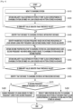
- FIG. 6 is a view for illustrating a method of controlling the mobile robot device 100 according to an embodiment.
- the mobile robot device 100 may obtain the first position relative to the charging station 200 (or docking point 210 of the charging station 200) based on a result obtained by canning the surroundings of the mobile robot device 100 by the LiDAR sensor 110 using the first frequency (S610).
- the first position relative to the charging station 200 may include information regarding the distance and the direction from the mobile robot device 100 to the charging station 200.
- the mobile robot device 100 may move to the charging station 200 based on the first position relative to the charging station 200 (S620).
- the mobile robot device 100 may identify whether the distance to the charging station 200 is within the first distance while moving (S630).
- the mobile robot device 100 may identify whether the distance to the charging station 200 is within the first distance based on the information regarding the first distance stored in memory 130.
- the mobile robot device 100 may identify whether the distance to the charging station 200 is within the first distance based on the similarity value between the pattern of the point cloud corresponding to the charging station 200 and the pattern stored in memory 130. When the similarity value is identified to be less than the threshold value, the mobile robot device 100 may identify that the distance to the charging station is within the first distance.
- the mobile robot device 100 may control the LiDAR sensor 110 to scan the surroundings of the mobile robot device 100 by changing the frequency of the LiDAR sensor 110 to the second frequency less than the first frequency (S640). In other words, the mobile robot device 100 may more accurately obtain the distance to the charging station 200 and the position thereof by decreasing the frequency of the LiDAR sensor 110.
- Various embodiments of the disclosure may be implemented as software including instructions stored in machine (e.g., computer)-readable storage media.
- the machine is a device that invokes instructions stored in the storage medium and is operated according to the invoked instructions, and may include an electronic device (e.g., mobile robot device 100) according to the disclosed embodiments.
- the instruction is executed by a processor, the processor may perform a function corresponding to the instruction directly or using other elements under the control of the processor.
- the instruction may include a code made by a compiler or a code executable by an interpreter.
- the machine-readable storage medium may be provided in a form of a non-transitory storage medium.
- the "non-transitory storage medium” is tangible and may not include signals, and it does not distinguish that data is semi-permanently or temporarily stored in the storage medium.
- non-transitory storage medium may include a buffer temporarily storing data.
- Each of the elements may include a single entity or a plurality of entities, and some sub-elements of the abovementioned sub-elements may be omitted or other sub-elements may be further included in various embodiments.
- some elements e.g., modules or programs
- the methods according to various embodiments of this disclosure may be provided to be included in a computer program product.
- the computer program product may be exchanged between a seller and a purchaser as a commercially available product.
- the computer program product may be distributed in the form of a machine-readable storage medium (e.g., compact disc read only memory (CD-ROM)) or distributed online (e.g., downloading or uploading) through an application store (e.g., PlayStoreTM) or directly between two user devices (e.g., smartphones).
- a machine-readable storage medium e.g., compact disc read only memory (CD-ROM)
- CD-ROM compact disc read only memory
- an application store e.g., PlayStoreTM
- smartphones directly between two user devices
- At least a part of the computer program product may be at least temporarily stored or temporarily generated in a device-readable storage medium such as a memory of a server of a manufacturer, a server of an application store, or a relay server.
Landscapes
- Engineering & Computer Science (AREA)
- Physics & Mathematics (AREA)
- Mechanical Engineering (AREA)
- Robotics (AREA)
- General Physics & Mathematics (AREA)
- Radar, Positioning & Navigation (AREA)
- Remote Sensing (AREA)
- Electromagnetism (AREA)
- Automation & Control Theory (AREA)
- Aviation & Aerospace Engineering (AREA)
- Computer Networks & Wireless Communication (AREA)
- Optics & Photonics (AREA)
- Evolutionary Computation (AREA)
- Fuzzy Systems (AREA)
- Mathematical Physics (AREA)
- Software Systems (AREA)
- Artificial Intelligence (AREA)
- Human Computer Interaction (AREA)
- Control Of Position, Course, Altitude, Or Attitude Of Moving Bodies (AREA)
- Charge And Discharge Circuits For Batteries Or The Like (AREA)
Applications Claiming Priority (4)
| Application Number | Priority Date | Filing Date | Title |
|---|---|---|---|
| KR1020190149864A KR102810058B1 (ko) | 2019-11-20 | 2019-11-20 | 이동 로봇 장치 및 이의 제어 방법 |
| EP24151251.6A EP4328696B1 (de) | 2019-11-20 | 2020-09-11 | Mobile robotervorrichtung und verfahren zur steuerung der mobilen robotervorrichtung |
| EP20889472.5A EP3996884A4 (de) | 2019-11-20 | 2020-09-11 | Mobile robotervorrichtung und verfahren zur steuerung einer mobilen robotervorrichtung |
| PCT/KR2020/012338 WO2021101047A1 (en) | 2019-11-20 | 2020-09-11 | Mobile robot device and method for controlling mobile robot device |
Related Parent Applications (3)
| Application Number | Title | Priority Date | Filing Date |
|---|---|---|---|
| EP20889472.5A Division EP3996884A4 (de) | 2019-11-20 | 2020-09-11 | Mobile robotervorrichtung und verfahren zur steuerung einer mobilen robotervorrichtung |
| EP24151251.6A Division EP4328696B1 (de) | 2019-11-20 | 2020-09-11 | Mobile robotervorrichtung und verfahren zur steuerung der mobilen robotervorrichtung |
| EP24151251.6A Division-Into EP4328696B1 (de) | 2019-11-20 | 2020-09-11 | Mobile robotervorrichtung und verfahren zur steuerung der mobilen robotervorrichtung |
Publications (2)
| Publication Number | Publication Date |
|---|---|
| EP4579283A2 true EP4579283A2 (de) | 2025-07-02 |
| EP4579283A3 EP4579283A3 (de) | 2025-07-09 |
Family
ID=75909275
Family Applications (3)
| Application Number | Title | Priority Date | Filing Date |
|---|---|---|---|
| EP24151251.6A Active EP4328696B1 (de) | 2019-11-20 | 2020-09-11 | Mobile robotervorrichtung und verfahren zur steuerung der mobilen robotervorrichtung |
| EP25176499.9A Pending EP4579283A3 (de) | 2019-11-20 | 2020-09-11 | Mobile robotervorrichtung und verfahren zur steuerung der mobilen robotervorrichtung |
| EP20889472.5A Withdrawn EP3996884A4 (de) | 2019-11-20 | 2020-09-11 | Mobile robotervorrichtung und verfahren zur steuerung einer mobilen robotervorrichtung |
Family Applications Before (1)
| Application Number | Title | Priority Date | Filing Date |
|---|---|---|---|
| EP24151251.6A Active EP4328696B1 (de) | 2019-11-20 | 2020-09-11 | Mobile robotervorrichtung und verfahren zur steuerung der mobilen robotervorrichtung |
Family Applications After (1)
| Application Number | Title | Priority Date | Filing Date |
|---|---|---|---|
| EP20889472.5A Withdrawn EP3996884A4 (de) | 2019-11-20 | 2020-09-11 | Mobile robotervorrichtung und verfahren zur steuerung einer mobilen robotervorrichtung |
Country Status (4)
| Country | Link |
|---|---|
| US (1) | US11609575B2 (de) |
| EP (3) | EP4328696B1 (de) |
| KR (2) | KR102810058B1 (de) |
| WO (1) | WO2021101047A1 (de) |
Families Citing this family (17)
| Publication number | Priority date | Publication date | Assignee | Title |
|---|---|---|---|---|
| WO2018204308A1 (en) | 2017-05-01 | 2018-11-08 | Symbol Technologies, Llc | Method and apparatus for object status detection |
| US11822333B2 (en) | 2020-03-30 | 2023-11-21 | Zebra Technologies Corporation | Method, system and apparatus for data capture illumination control |
| KR102423497B1 (ko) * | 2020-07-02 | 2022-07-21 | 엘지전자 주식회사 | 로봇 청소기의 제어 방법 |
| CN113220041A (zh) * | 2021-02-25 | 2021-08-06 | 孟姣姣 | 一种加药机及其控制系统 |
| US11954882B2 (en) | 2021-06-17 | 2024-04-09 | Zebra Technologies Corporation | Feature-based georegistration for mobile computing devices |
| US20230043172A1 (en) * | 2021-08-06 | 2023-02-09 | Zebra Technologies Corporation | Adaptive Perimeter Intrusion Detection for Mobile Automation Apparatus |
| CN113809810B (zh) * | 2021-11-16 | 2022-02-15 | 中国科学院自动化研究所 | 一种机器人自主充电方法及装置 |
| KR102727342B1 (ko) * | 2021-12-24 | 2024-11-07 | 주식회사 제타뱅크 | 도킹 시 라이다를 이용하는 이동 로봇 충전 시스템 |
| CN114665544A (zh) * | 2022-03-14 | 2022-06-24 | 北京石头世纪科技股份有限公司 | 一种自移动设备、充电桩及自主充电系统 |
| KR102436960B1 (ko) * | 2022-04-28 | 2022-08-29 | 가천대학교 산학협력단 | 홈로봇을 위한 충전시스템 제공방법 |
| KR102688274B1 (ko) * | 2022-06-03 | 2024-07-25 | 코가로보틱스 주식회사 | 이동형 로봇 및 이동형 로봇의 충전 스테이션 도킹 방법 |
| WO2024008615A1 (de) * | 2022-07-08 | 2024-01-11 | Robert Bosch Gmbh | Verfahren zum bestimmen einer position eines vorbestimmten objekts |
| CN115421486B (zh) * | 2022-09-01 | 2025-08-26 | 深圳市正浩创新科技股份有限公司 | 返航控制方法、装置、计算机可读介质及自移动设备 |
| WO2023156840A1 (en) * | 2022-09-30 | 2023-08-24 | Mohammadnejad Zahra | Multiple cooperative vacuum robots based on dynamic mobile ad-hoc networks routing |
| KR102559300B1 (ko) * | 2022-12-28 | 2023-07-25 | 주식회사 클로봇 | 무인 이동체 및 무인 이동체의 도킹 제어 방법 |
| US12339665B2 (en) * | 2023-02-24 | 2025-06-24 | Ford Global Technologies, Llc | Docking system and associated method |
| SE547246C2 (en) * | 2023-10-23 | 2025-06-10 | Husqvarna Ab | Improved navigation for a robotic work tool system |
Family Cites Families (52)
| Publication number | Priority date | Publication date | Assignee | Title |
|---|---|---|---|---|
| US5202742A (en) * | 1990-10-03 | 1993-04-13 | Aisin Seiki Kabushiki Kaisha | Laser radar for a vehicle lateral guidance system |
| JPH07209421A (ja) | 1994-01-26 | 1995-08-11 | Nikon Corp | 障害物検知装置 |
| JP3104558B2 (ja) * | 1995-02-01 | 2000-10-30 | トヨタ自動車株式会社 | 車載用レーダ装置 |
| EP2273336B1 (de) | 2004-01-21 | 2013-10-02 | iRobot Corporation | Verfahren zum Andocken eines autonomen Roboters |
| US7332890B2 (en) * | 2004-01-21 | 2008-02-19 | Irobot Corporation | Autonomous robot auto-docking and energy management systems and methods |
| KR100645381B1 (ko) | 2005-08-31 | 2006-11-14 | 삼성광주전자 주식회사 | 로봇청소기의 외부충전 복귀장치 및 복귀방법 |
| KR100740007B1 (ko) | 2006-12-20 | 2007-07-16 | (주)다사테크 | 충전스테이션의 형상을 이용한 충전단자 위치 인식 시스템 |
| KR101415879B1 (ko) * | 2008-01-04 | 2014-07-07 | 삼성전자 주식회사 | 이동 로봇을 도킹시키는 방법 및 장치 |
| NL1035980C (nl) * | 2008-09-25 | 2010-03-26 | Lely Patent Nv | Onbemand voertuig voor het verplaatsen van mest. |
| JP2012063236A (ja) * | 2010-09-16 | 2012-03-29 | Ricoh Co Ltd | レーザレーダ装置 |
| US9145110B2 (en) * | 2011-10-27 | 2015-09-29 | Ford Global Technologies, Llc | Vehicle wireless charger safety system |
| US9052721B1 (en) * | 2012-08-28 | 2015-06-09 | Google Inc. | Method for correcting alignment of vehicle mounted laser scans with an elevation map for obstacle detection |
| DE102014208991A1 (de) | 2013-05-15 | 2014-11-20 | Ford Global Technologies, Llc | Sicherheitssystem für drahtloses Fahrzeugaufladegerät |
| CN104282168B (zh) | 2013-07-05 | 2017-09-01 | 国民技术股份有限公司 | 停车管理方法、装置及系统 |
| KR101604762B1 (ko) | 2014-09-11 | 2016-03-21 | 만도헬라일렉트로닉스(주) | 초음파 센서 제어장치 및 그 제어방법 |
| US9630318B2 (en) * | 2014-10-02 | 2017-04-25 | Brain Corporation | Feature detection apparatus and methods for training of robotic navigation |
| US9510505B2 (en) * | 2014-10-10 | 2016-12-06 | Irobot Corporation | Autonomous robot localization |
| DE102015100706A1 (de) | 2014-12-15 | 2016-06-16 | Vorwerk & Co. Interholding Gmbh | Selbsttätig verfahrbares Reinigungsgerät |
| US9717387B1 (en) * | 2015-02-26 | 2017-08-01 | Brain Corporation | Apparatus and methods for programming and training of robotic household appliances |
| US11069082B1 (en) * | 2015-08-23 | 2021-07-20 | AI Incorporated | Remote distance estimation system and method |
| US10788836B2 (en) * | 2016-02-29 | 2020-09-29 | AI Incorporated | Obstacle recognition method for autonomous robots |
| US11449061B2 (en) * | 2016-02-29 | 2022-09-20 | AI Incorporated | Obstacle recognition method for autonomous robots |
| US11037320B1 (en) * | 2016-03-01 | 2021-06-15 | AI Incorporated | Method for estimating distance using point measurement and color depth |
| US11036230B1 (en) * | 2016-03-03 | 2021-06-15 | AI Incorporated | Method for developing navigation plan in a robotic floor-cleaning device |
| US9873408B2 (en) | 2016-05-11 | 2018-01-23 | Peter D. Capizzo | Device for refueling, exchanging, and charging power sources on remote controlled vehicles, UAVs, drones, or any type of robotic vehicle or machine with mobility |
| US10137890B2 (en) * | 2016-06-28 | 2018-11-27 | Toyota Motor Engineering & Manufacturing North America, Inc. | Occluded obstacle classification for vehicles |
| EP4177639A1 (de) | 2016-11-30 | 2023-05-10 | Yujin Robot Co., Ltd. | Roboter staubsauger mit multichannel-lidar-basierter hinderniserkennung und schlupferkennung |
| US10962647B2 (en) * | 2016-11-30 | 2021-03-30 | Yujin Robot Co., Ltd. | Lidar apparatus based on time of flight and moving object |
| KR101878827B1 (ko) * | 2016-11-30 | 2018-07-17 | 주식회사 유진로봇 | 다채널 라이더 기반 이동로봇의 장애물 검출 장치 및 방법, 및 이를 구비한 이동로봇 |
| KR102631151B1 (ko) | 2016-12-23 | 2024-01-31 | 엘지전자 주식회사 | 청소 로봇 |
| KR101984101B1 (ko) * | 2017-03-06 | 2019-05-30 | 엘지전자 주식회사 | 청소기 및 그 제어방법 |
| US10401866B2 (en) * | 2017-05-03 | 2019-09-03 | GM Global Technology Operations LLC | Methods and systems for lidar point cloud anomalies |
| US11348269B1 (en) * | 2017-07-27 | 2022-05-31 | AI Incorporated | Method and apparatus for combining data to construct a floor plan |
| KR101980697B1 (ko) | 2018-05-09 | 2019-05-22 | 주식회사 에스오에스랩 | 객체 정보 획득 장치 및 방법 |
| KR102050632B1 (ko) * | 2017-08-02 | 2019-12-03 | 주식회사 에스오에스랩 | 다채널 라이다 센서 모듈 |
| CN109521756B (zh) * | 2017-09-18 | 2022-03-08 | 阿波罗智能技术(北京)有限公司 | 用于无人驾驶车辆的障碍物运动信息生成方法和装置 |
| US11579298B2 (en) | 2017-09-20 | 2023-02-14 | Yujin Robot Co., Ltd. | Hybrid sensor and compact Lidar sensor |
| US10401864B2 (en) * | 2017-09-22 | 2019-09-03 | Locus Robotics Corp. | Electrical charging system and method for an autonomous robot |
| US10638906B2 (en) | 2017-12-15 | 2020-05-05 | Neato Robotics, Inc. | Conversion of cleaning robot camera images to floorplan for user interaction |
| CN110389341B (zh) * | 2018-04-18 | 2021-06-25 | 深圳市优必选科技有限公司 | 充电桩识别方法、装置、机器人及计算机可读存储介质 |
| CN110412530B (zh) * | 2018-04-27 | 2021-09-17 | 深圳市优必选科技有限公司 | 一种识别充电桩的方法、装置及机器人 |
| US11874399B2 (en) * | 2018-05-16 | 2024-01-16 | Yujin Robot Co., Ltd. | 3D scanning LIDAR sensor |
| CN109074083B (zh) * | 2018-06-08 | 2022-02-18 | 珊口(深圳)智能科技有限公司 | 移动控制方法、移动机器人及计算机存储介质 |
| KR102238352B1 (ko) * | 2018-08-05 | 2021-04-09 | 엘지전자 주식회사 | 스테이션 장치 및 이동 로봇 시스템 |
| CN111060101B (zh) * | 2018-10-16 | 2022-06-28 | 深圳市优必选科技有限公司 | 视觉辅助的距离slam方法及装置、机器人 |
| JP6824236B2 (ja) * | 2018-10-23 | 2021-02-03 | 三菱電機株式会社 | レーザ距離測定装置 |
| CN109586360B (zh) * | 2018-11-09 | 2020-09-22 | 深圳市银星智能科技股份有限公司 | 一种机器人自动充电的方法、装置、充电桩和机器人 |
| KR102302199B1 (ko) * | 2018-11-21 | 2021-09-14 | 삼성전자주식회사 | 이동 장치 및 이동 장치의 객체 감지 방법 |
| CN209437169U (zh) * | 2018-12-14 | 2019-09-27 | 江苏美的清洁电器股份有限公司 | 充电座及可充电机器人 |
| CN109623839A (zh) * | 2018-12-24 | 2019-04-16 | 西南交通大学 | 配电站室内设备地空协同巡检装置及其巡检方法 |
| US20220134567A1 (en) * | 2019-02-25 | 2022-05-05 | The University Of Tokyo | Robot system, robot control device, and robot control program |
| US11560153B2 (en) * | 2019-03-07 | 2023-01-24 | 6 River Systems, Llc | Systems and methods for collision avoidance by autonomous vehicles |
-
2019
- 2019-11-20 KR KR1020190149864A patent/KR102810058B1/ko active Active
-
2020
- 2020-09-08 US US17/014,004 patent/US11609575B2/en active Active
- 2020-09-11 EP EP24151251.6A patent/EP4328696B1/de active Active
- 2020-09-11 WO PCT/KR2020/012338 patent/WO2021101047A1/en not_active Ceased
- 2020-09-11 EP EP25176499.9A patent/EP4579283A3/de active Pending
- 2020-09-11 EP EP20889472.5A patent/EP3996884A4/de not_active Withdrawn
-
2023
- 2023-11-09 KR KR1020230154590A patent/KR20230159347A/ko active Pending
Also Published As
| Publication number | Publication date |
|---|---|
| EP3996884A1 (de) | 2022-05-18 |
| KR102810058B1 (ko) | 2025-05-21 |
| EP4328696C0 (de) | 2025-07-09 |
| US11609575B2 (en) | 2023-03-21 |
| EP4579283A3 (de) | 2025-07-09 |
| KR20230159347A (ko) | 2023-11-21 |
| EP4328696A3 (de) | 2024-07-24 |
| US20210146552A1 (en) | 2021-05-20 |
| EP3996884A4 (de) | 2022-08-31 |
| KR20210061842A (ko) | 2021-05-28 |
| WO2021101047A1 (en) | 2021-05-27 |
| EP4328696B1 (de) | 2025-07-09 |
| EP4328696A2 (de) | 2024-02-28 |
Similar Documents
| Publication | Publication Date | Title |
|---|---|---|
| EP4328696B1 (de) | Mobile robotervorrichtung und verfahren zur steuerung der mobilen robotervorrichtung | |
| US11225275B2 (en) | Method, system and apparatus for self-driving vehicle obstacle avoidance | |
| US20180033315A1 (en) | Systems and methods for transporting products via unmanned aerial vehicles and mobile relay stations | |
| JP2017162435A (ja) | 自律移動体ガイダンスシステム、自律移動体をガイドする方法、およびプログラム | |
| CN105119338A (zh) | 移动机器人充电控制系统及方法 | |
| CN112236733A (zh) | 一种将移动机器人引导到坞站的计算机化系统及其使用方法 | |
| CN104793614A (zh) | 自动行走设备回归引导系统 | |
| JP2011245295A (ja) | 方向装置およびそれを用いた動作システム | |
| CN111247390A (zh) | Vslam的并发的重新定位和重新初始化 | |
| CN108932515B (zh) | 一种基于闭环检测进行拓扑节点位置校正的方法和装置 | |
| US20230356399A1 (en) | Driving robot apparatus, controlling method of the driving robot apparatus, and recording medium having recorded thereon computer program | |
| CN108988403A (zh) | 自主充电系统、自主移动设备以及充电桩 | |
| KR101722768B1 (ko) | Rtls를 이용한 자동 무선 충전 방법 | |
| JP2014010797A (ja) | 自律走行装置 | |
| KR102855642B1 (ko) | 이동 로봇, 마커 재인식을 수행하는 이동 로봇의 도킹 제어 방법 및 프로그램 | |
| US20230191599A1 (en) | Robot and control method for robot | |
| US11872705B2 (en) | Autonomous mobile robot utilizing an omni-directional waypoint and control method thereof | |
| US12181285B2 (en) | Electronic apparatus and control method thereof | |
| WO2020123214A1 (en) | Rfid-based navigation of an autonomous guided vehicle | |
| US12468305B2 (en) | Electronic device and method for controlling thereof | |
| WO2023065170A1 (en) | Robotic cart | |
| US12481286B2 (en) | Robot, charging station, and robot charging system comprising same | |
| KR102718177B1 (ko) | 이동형 모빌리티의 경로 생성 시스템 | |
| HK40090809A (zh) | 充电控制方法及充电控制装置 | |
| CN120447545A (zh) | 可移动设备及标签设备的控制方法、可移动设备 |
Legal Events
| Date | Code | Title | Description |
|---|---|---|---|
| PUAI | Public reference made under article 153(3) epc to a published international application that has entered the european phase |
Free format text: ORIGINAL CODE: 0009012 |
|
| STAA | Information on the status of an ep patent application or granted ep patent |
Free format text: STATUS: THE APPLICATION HAS BEEN PUBLISHED |
|
| REG | Reference to a national code |
Ref country code: DE Ref legal event code: R079 Free format text: PREVIOUS MAIN CLASS: G01S0017890000 Ipc: G05D0001000000 |
|
| PUAL | Search report despatched |
Free format text: ORIGINAL CODE: 0009013 |
|
| AC | Divisional application: reference to earlier application |
Ref document number: 3996884 Country of ref document: EP Kind code of ref document: P Ref document number: 4328696 Country of ref document: EP Kind code of ref document: P |
|
| AK | Designated contracting states |
Kind code of ref document: A2 Designated state(s): AL AT BE BG CH CY CZ DE DK EE ES FI FR GB GR HR HU IE IS IT LI LT LU LV MC MK MT NL NO PL PT RO RS SE SI SK SM TR |
|
| AK | Designated contracting states |
Kind code of ref document: A3 Designated state(s): AL AT BE BG CH CY CZ DE DK EE ES FI FR GB GR HR HU IE IS IT LI LT LU LV MC MK MT NL NO PL PT RO RS SE SI SK SM TR |
|
| RIC1 | Information provided on ipc code assigned before grant |
Ipc: G01S 17/89 20200101ALI20250604BHEP Ipc: G01S 17/42 20060101ALI20250604BHEP Ipc: G01S 17/10 20200101ALI20250604BHEP Ipc: A47L 9/28 20060101ALI20250604BHEP Ipc: A47L 11/40 20060101ALI20250604BHEP Ipc: G05D 1/00 20240101AFI20250604BHEP |
|
| STAA | Information on the status of an ep patent application or granted ep patent |
Free format text: STATUS: REQUEST FOR EXAMINATION WAS MADE |
|
| STAA | Information on the status of an ep patent application or granted ep patent |
Free format text: STATUS: EXAMINATION IS IN PROGRESS |
|
| 17P | Request for examination filed |
Effective date: 20251001 |
|
| 17Q | First examination report despatched |
Effective date: 20251030 |