EP4579136A1 - Ofen - Google Patents
Ofen Download PDFInfo
- Publication number
- EP4579136A1 EP4579136A1 EP24208672.6A EP24208672A EP4579136A1 EP 4579136 A1 EP4579136 A1 EP 4579136A1 EP 24208672 A EP24208672 A EP 24208672A EP 4579136 A1 EP4579136 A1 EP 4579136A1
- Authority
- EP
- European Patent Office
- Prior art keywords
- fan
- oven
- rear wall
- cooking
- air guide
- Prior art date
- Legal status (The legal status is an assumption and is not a legal conclusion. Google has not performed a legal analysis and makes no representation as to the accuracy of the status listed.)
- Pending
Links
Images

Classifications
-
- F—MECHANICAL ENGINEERING; LIGHTING; HEATING; WEAPONS; BLASTING
- F24—HEATING; RANGES; VENTILATING
- F24C—DOMESTIC STOVES OR RANGES ; DETAILS OF DOMESTIC STOVES OR RANGES, OF GENERAL APPLICATION
- F24C15/00—Details
- F24C15/32—Arrangements of ducts for hot gases, e.g. in or around baking ovens
- F24C15/322—Arrangements of ducts for hot gases, e.g. in or around baking ovens with forced circulation
- F24C15/325—Arrangements of ducts for hot gases, e.g. in or around baking ovens with forced circulation electrically-heated
-
- F—MECHANICAL ENGINEERING; LIGHTING; HEATING; WEAPONS; BLASTING
- F24—HEATING; RANGES; VENTILATING
- F24C—DOMESTIC STOVES OR RANGES ; DETAILS OF DOMESTIC STOVES OR RANGES, OF GENERAL APPLICATION
- F24C7/00—Stoves or ranges heated by electric energy
- F24C7/08—Arrangement or mounting of control or safety devices
- F24C7/082—Arrangement or mounting of control or safety devices on ranges, e.g. control panels, illumination
- F24C7/085—Arrangement or mounting of control or safety devices on ranges, e.g. control panels, illumination on baking ovens
Definitions
- the aim of the present invention is the realization of an oven which automatically adjusts the air distribution depending on the needs and type of the foodstuff and the cooking function during the cooking process so as to ensure homogeneous cooking.
- Another aim of the present invention is the realization of an oven which can guide more air flow to cook the bottom or top of the foodstuff to be cooked better after reaching a certain cooking level.
- Another aim of the present invention is the realization of an oven which eliminates the problem, encountered in the state of the art, of the air losing speed while flowing from the rear side of the oven towards the front side thereof, which increase the flow speed of air towards the front side of the oven and which prevents the loss in speed and heat at the front wall region of the oven.
- Another aim of the present invention is the realization of an oven which reduces energy consumption.
- the oven realized in order to attain the aim of the present invention, explicated in the first claim and the respective claims thereof, comprises a cooking chamber which is defined by first and second side walls, a rear wall, an upper wall, a lower wall and a door; at least one fan which is positioned on the rear wall; at least one heater which is positioned around the fan; a fan sheet metal which is mounted on the rear wall and which is disposed in front of the fan and heater; at least one power source which receives external electrical power and which distributes the power to the components in the oven; at least one movable air guide which is disposed between the fan sheet metal and the rear wall and which can be positioned at any point on the rear wall; and a control panel which communicates with the fan and/or the movable air guide.
- the oven of the present invention comprises at least one circuit board which calculates the rotation speed of the fan operating at a fixed speed for a predetermined period of time after this period is reached and/or which decides that the fan is rotated clockwise or counterclockwise, and a control panel which communicates with the circuit board and which is configured to give commands to the fan.
- the oven of the present invention comprises at least one measuring member which measures the temperature and/or humidity value in the cooking chamber and which is positioned in the cooking chamber.
- the oven of the present invention comprises a circuit board which, according to the information received from the measuring member positioned in the cooking chamber, makes a comparison and runs an algorithm when the temperature of the cooking chamber is equal to or above a predetermined temperature value and which decides on the fan speed, fan rotation direction and position of the movable air guide so as to calculate the air flow rate circulating in the cooking chamber; and a control panel which communicates with the circuit board and which is configured to give commands to the fan and/or the movable air guide.
- the oven of the present invention comprises a circuit board which makes a comparison and runs an algorithm when the flow rate in the cooking chamber is equal to or above a predetermined flow rate value and which decides on the fan speed, fan rotation direction and position of the movable air guide so as to calculate the air flow rate circulating in the cooking chamber; and a control panel which communicates with the circuit board and which is configured to give commands to the fan and/or the movable air guide.
- the oven of the present invention comprises at least one movable air guide having a first edge which is at least partially fixed to the rear wall and a fin-shaped surface which extends from the rear wall towards the fan sheet metal planarly or at a certain angle.
- the oven of the present invention comprises a control panel where cooking time and cooking temperature can be selected automatically.
- the oven of the present invention comprises a control panel having at least one selection member which enables the manual input of a cooking time and/or cooking temperature.
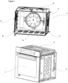
- the oven (1) of the present invention comprises a first and second side wall (2, 3); a rear wall (4); an upper wall (5); a lower wall (6); and a door (7).
- An arm (not shown in the figures) is positioned on the door (7) so as to open the door (7) from top to bottom, from left to right or from right to left.
- the oven (1) comprises a cooking chamber (8) which is defined by the first and second side walls (2, 3), a rear wall (4), an upper wall (5), a lower wall (6) and a door (7).
- the oven (1) comprises at least one fan (9) which is positioned on the rear wall (4), a heater which is disposed around the fan (9) and at least one power source (11).
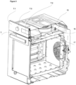
- a fan sheet metal (12) which is mounted on the rear wall (4) at the corners is provided in front of the said fan (9) and the heater (10).
- the hot air in the cooking chamber (8), after passing through the fan (9) and the heater (10), the hot air enters the central region of the fan sheet metal (12) and passes through the jet nozzles (16) provided on the upper wall (5) and lower wall (6) of the oven (1).
- the air flow is accelerated and guided to the foodstuff surface.
- the oven (1) comprises a cooking chamber (8) which is defined by first and second side walls (2, 3), a rear wall (4), an upper wall (5), a lower wall (6) and a door (7); at least one fan (9) which is positioned on the rear wall (4); at least one heater (10) which is positioned around the fan (9); a fan sheet metal (12) which is mounted on the rear wall (4) and which is disposed in front of the fan (9) and heater (10); at least one power source (11) which receives external electrical power and which distributes the power to the components in the oven (1); at least one movable air guide (13) which is disposed between the fan sheet metal (12) and the rear wall (4) and which can be positioned at any point on the rear wall (4); and a control panel (7.1) which communicates with the fan (9) and/or the movable air guide (13).
- a cooking chamber (8) which is defined by first and second side walls (2, 3), a rear wall (4), an upper wall (5), a lower wall (6) and a
- the air flow transmitted from the upper part and/or lower part of the oven (1) to the cooking chamber (8) by means of the movable air guide (13) is dynamically controlled throughout the cooking process depending on the needs of the foodstuff or the cooking function, thus achieving the desired cooking quality. Only by this manner, the optimum internal cooking balance and the golden-brownness of the bottom/top surface can be achieved for foodstuffs such as bread and pizza.
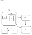
- the measuring member (14) is connected to the control panel (7.1) and the circuit board (7.4).
- the oven (1) comprises at least one display member (19) which is positioned on the upper wall (5) or on the rear wall (4) or in any intersection of the rear wall (4) and the upper wall (5), in a position so as to see the entirety of the foodstuff to be cooked in the cooking chamber (8) in order to determine the cooking degree of the foodstuff to be cooked together with a measuring member (14) or alone, and which communicates with the control panel (7.1) and the circuit board (7.4).
- the oven (1) comprises a control panel (7.1) which is configured to give a command to enable the fan (9) to rotate at the fan (9) speed determined according to the information received from the said circuit board (7.4), to rotate the fan (9) clockwise or counterclockwise, and to move the air guide (13) to a certain position at a certain angle.
- a control panel (7.1) which is configured to give a command to enable the fan (9) to rotate at the fan (9) speed determined according to the information received from the said circuit board (7.4), to rotate the fan (9) clockwise or counterclockwise, and to move the air guide (13) to a certain position at a certain angle.
- the oven (1) comprises a control panel (7.1) having a user interface with at least one screen (7.2) and at least one selection member (7.3), and a memory (7.5) so as to display user interface windows and receive one or more inputs from the user.
- the screen (7.2) comprises menus which enable the user to select the type of foodstuff to be cooked, which automatically adjust the temperature and cooking time depending on the foodstuff type selection and which are recorded in the memory (7.5).
- a cooking time and/or cooking temperature selected by the user can also be entered manually by means of at least one selection member (7.3).
- the selection member (7.3) can be a button, a touch-sensitive screen or a keypad to provide additional inputs by the user.
- the screen (7.2) is a touch screen for displaying graphical user interfaces and receiving inputs.
- additional touch-sensitive buttons are provided next to the screen (7.2).
- the oven (1) comprises at least one circuit board (7.4) which calculates the rotation speed of the fan (9) operating at a fixed speed for a predetermined period of time after this period is reached and/or which decides that the fan (9) is rotated clockwise or counterclockwise, and a control panel (7.1) which communicates with the circuit board (7.4) and which is configured to give commands to the fan (9).
- the oven (1) comprises a circuit board (7.4) which, according to the information received from the measuring member (14) positioned in the cooking chamber (8), makes a comparison and runs an algorithm when the temperature of the cooking chamber (8) is equal to or above a predetermined temperature value and which decides on the fan (9) speed, fan (9) rotation direction and position of the movable air guide (13) so as to calculate the air flow rate circulating in the cooking chamber (8); and a control panel (7.1) which communicates with the circuit board (7.4) and which is configured to give commands to the fan (9) and/or the movable air guide (13).
- the oven (1) comprises a circuit board (7.4) which makes a comparison and runs an algorithm when the flow rate in the cooking chamber (8) is equal to or above a predetermined flow rate value and which decides on the fan (9) speed, fan (9) rotation direction and position of the movable air guide (13) so as to calculate the air flow rate circulating in the cooking chamber (8); and a control panel (7.1) which communicates with the circuit board (7.4) and which is configured to give commands to the fan (9) and/or the movable air guide (13).
- a circuit board (7.4) which makes a comparison and runs an algorithm when the flow rate in the cooking chamber (8) is equal to or above a predetermined flow rate value and which decides on the fan (9) speed, fan (9) rotation direction and position of the movable air guide (13) so as to calculate the air flow rate circulating in the cooking chamber (8)
- a control panel (7.1) which communicates with the circuit board (7.4) and which is configured to give commands to the fan (9) and/or the movable air guide (13).
- the movable air guide (13) comprises a first edge (13.1) which is at least partially fixed to the rear wall (4) and a fin-shaped surface (13.2) which extends from the rear wall (4) towards the fan sheet metal (12) planarly or at a certain angle.
- the said air guide (13) is moved by at least one power source (11).
- the oven (1) comprises a plurality of air guides (13) which are positioned on the rear wall (4) at certain intervals such that the surfaces (13.2) thereof do not come into contact with each other.
- the oven (1) may comprise a plurality of power sources (11).
- the air guide (13) and the oven (1) may be triggered by two separate power sources (11).
- the oven (1) comprises an upper plate (15) which is placed under the upper wall (5) and a lower plate (16) which is placed on the lower wall (6).
- Said upper plate (15) and lower plate (16) comprise a plurality of jet nozzles (17) arranged thereon in rows and columns.
- the said jet nozzles (16) are configured to transmit hot or cold impingement air towards the cooking chamber (8) at a high speed.
- the relatively hot air entering the central region of the fan sheet metal (12) passes through the fan (9) and the heater (10) and then reaches at least one ventilation member (18) positioned between the upper wall (5) and the upper plate (14) and/or between the lower wall (6) and the lower plate (15).
- the oven (1) comprises a circuit board (7.4) which calculates the positioning of the movable air guide (13) so as to guide the air towards the jet nozzles (17) provided on an upper plate (15) disposed under the upper wall (5) and/or the jet nozzles (17) provided on a lower plate (16) disposed on the lower wall (6) when a certain percentage of the cooking time corresponding to the selected foodstuff recorded in the memory (7.5) is reached after the user selects the type of foodstuff to be cooked on the screen (7.2) and/or which calculates the speed of the fan (9) and/or the clockwise or counterclockwise rotation of the fan (9); and a control panel (7.1) which gives the movement command of the air guide (13) and/or the fan (9) depending on the information received from the circuit board (7.4).
- a control panel (7.1) which gives the movement command of the air guide (13) and/or the fan (9) depending on the information received from the circuit board (7.4).
- the amount of air coming out from the top and bottom depending on the rotation direction of the fan (9) and the angle (opening) of the movable air guide (13) is adjusted adaptively according to the selected cooking function or the foodstuff type in the automatic menus.
- the jet nozzles (17) disposed on both the upper plate (15) and the lower plate (16) are active until a certain cooking level.
- the air flow path created by the air guide (13) and/or the fan (9) rotated counterclockwise is delivered to the nozzles (17) on the lower plate (16) of the oven (1).
- the air flow path created by the air guide (13) and/or the fan (9) rotated clockwise is delivered to the nozzles (17) on the upper plate (15) of the oven (1).
- the circuit board (7.4) is positioned on the upper wall (5).
- control panel (7.1) comprises the circuit board (7.4).
- the oven (1) further comprises at least one ventilation member (18) which is positioned between the upper wall (5) and the upper plate (14) and/or between the lower wall (6) and the lower plate (15).
- the air flow path created by the air guide (13) and/or the fan (9) rotated clockwise by the command coming from the control panel (7.1) to be delivered to the nozzles (17) on the upper plate (15) of the oven (1) differs from the air flow path created by the air guide (13) and/or the fan (9) rotated counterclockwise to be delivered to the nozzles (17) on the lower plate (16) of the oven (1).
- the flow rate value reaching the nozzles (17) positioned on the upper plate (15) and the lower plate (16) can be changed depending on the rotation direction of the fan (9) and the position and/or angle of the air guide (13).
- the oven is an oven (1) having the air impingement jet technology.
Landscapes
- Engineering & Computer Science (AREA)
- Chemical & Material Sciences (AREA)
- Combustion & Propulsion (AREA)
- Mechanical Engineering (AREA)
- General Engineering & Computer Science (AREA)
- Electric Stoves And Ranges (AREA)
Applications Claiming Priority (1)
| Application Number | Priority Date | Filing Date | Title |
|---|---|---|---|
| TR202319219 | 2023-12-28 |
Publications (1)
| Publication Number | Publication Date |
|---|---|
| EP4579136A1 true EP4579136A1 (de) | 2025-07-02 |
Family
ID=93283745
Family Applications (1)
| Application Number | Title | Priority Date | Filing Date |
|---|---|---|---|
| EP24208672.6A Pending EP4579136A1 (de) | 2023-12-28 | 2024-10-24 | Ofen |
Country Status (1)
| Country | Link |
|---|---|
| EP (1) | EP4579136A1 (de) |
Citations (5)
| Publication number | Priority date | Publication date | Assignee | Title |
|---|---|---|---|---|
| JPH11325478A (ja) * | 1998-05-19 | 1999-11-26 | Toshiba Corp | 加熱調理器 |
| JP2003214398A (ja) * | 2002-01-23 | 2003-07-30 | Sharp Corp | 送風装置及びこれを備えた加熱調理器 |
| EP2048442A2 (de) * | 2007-10-09 | 2009-04-15 | Samsung Electronics Co., Ltd. | Kochvorrichtung und Steuerungsverfahren dafür |
| US8217314B2 (en) * | 2007-06-13 | 2012-07-10 | Samsung Electronics Co., Ltd. | Cooking apparatus with divider |
| EP3425286B1 (de) * | 2017-07-07 | 2020-11-25 | Vestel Beyaz Esya Sanayi Ve Ticaret A.S. | Kochvorrichtung und betriebsverfahren dafür |
-
2024
- 2024-10-24 EP EP24208672.6A patent/EP4579136A1/de active Pending
Patent Citations (5)
| Publication number | Priority date | Publication date | Assignee | Title |
|---|---|---|---|---|
| JPH11325478A (ja) * | 1998-05-19 | 1999-11-26 | Toshiba Corp | 加熱調理器 |
| JP2003214398A (ja) * | 2002-01-23 | 2003-07-30 | Sharp Corp | 送風装置及びこれを備えた加熱調理器 |
| US8217314B2 (en) * | 2007-06-13 | 2012-07-10 | Samsung Electronics Co., Ltd. | Cooking apparatus with divider |
| EP2048442A2 (de) * | 2007-10-09 | 2009-04-15 | Samsung Electronics Co., Ltd. | Kochvorrichtung und Steuerungsverfahren dafür |
| EP3425286B1 (de) * | 2017-07-07 | 2020-11-25 | Vestel Beyaz Esya Sanayi Ve Ticaret A.S. | Kochvorrichtung und betriebsverfahren dafür |
Similar Documents
| Publication | Publication Date | Title |
|---|---|---|
| US11602149B2 (en) | Food preparation apparatus and methods | |
| US8642928B2 (en) | Temperature control for cooking appliance including combination heating system | |
| US8851061B2 (en) | Oven with ambient air cooling | |
| US8063342B2 (en) | Cooking oven | |
| US7750271B2 (en) | Systems and methods for controlling oven cooking | |
| HK1204228A1 (en) | Conveyor oven | |
| CN108402920A (zh) | 一种全方位加热食物的电烤箱 | |
| EP4359710A1 (de) | Kombinationsofen mit unabhängigem dampferzeugungselement | |
| JP2012037219A (ja) | 加熱調理器 | |
| US20250321011A1 (en) | Combination oven control interface | |
| JP2014030462A (ja) | 加熱調理器 | |
| EP3549391A1 (de) | Anwendungssteuerung für hf-ofenenergie | |
| EP4579136A1 (de) | Ofen | |
| JP2019020122A (ja) | 加熱調理器 | |
| KR102841076B1 (ko) | 조리기기 | |
| TR2023019219A2 (tr) | Çarpan hava jet teknoloji̇si̇ne sahi̇p bi̇r firin | |
| JP6157913B2 (ja) | 加熱調理器 | |
| EP4398726A1 (de) | Multifunktionaler elektrischer ofen | |
| US11988392B2 (en) | Removable heating element cover for an oven appliance and methods of detecting same | |
| EP2370745B1 (de) | Ofen mit einer gebläseabdeckplatte | |
| EP4321809B1 (de) | Ofen mit luftdüsen und beweglichem mechanismus, der über den düsen geöffnet/geschlossen werden kann | |
| EP4737803A1 (de) | Kochgerät und steuerungsverfahren dafür | |
| CN119055080B (zh) | 烹饪系统及烹饪方法 | |
| JP2014035108A (ja) | 加熱調理器 | |
| US20260126185A1 (en) | Cooking appliance and control method thereof |
Legal Events
| Date | Code | Title | Description |
|---|---|---|---|
| PUAI | Public reference made under article 153(3) epc to a published international application that has entered the european phase |
Free format text: ORIGINAL CODE: 0009012 |
|
| STAA | Information on the status of an ep patent application or granted ep patent |
Free format text: STATUS: REQUEST FOR EXAMINATION WAS MADE |
|
| 17P | Request for examination filed |
Effective date: 20241024 |
|
| AK | Designated contracting states |
Kind code of ref document: A1 Designated state(s): AL AT BE BG CH CY CZ DE DK EE ES FI FR GB GR HR HU IE IS IT LI LT LU LV MC ME MK MT NL NO PL PT RO RS SE SI SK SM TR |
|
| STAA | Information on the status of an ep patent application or granted ep patent |
Free format text: STATUS: THE APPLICATION IS DEEMED TO BE WITHDRAWN |