EP4579108A1 - Segment seal - Google Patents
Segment seal Download PDFInfo
- Publication number
- EP4579108A1 EP4579108A1 EP23857323.2A EP23857323A EP4579108A1 EP 4579108 A1 EP4579108 A1 EP 4579108A1 EP 23857323 A EP23857323 A EP 23857323A EP 4579108 A1 EP4579108 A1 EP 4579108A1
- Authority
- EP
- European Patent Office
- Prior art keywords
- ring
- resin
- base ring
- segment seal
- resin ring
- Prior art date
- Legal status (The legal status is an assumption and is not a legal conclusion. Google has not performed a legal analysis and makes no representation as to the accuracy of the status listed.)
- Withdrawn
Links
Images





Classifications
-
- F—MECHANICAL ENGINEERING; LIGHTING; HEATING; WEAPONS; BLASTING
- F16—ENGINEERING ELEMENTS AND UNITS; GENERAL MEASURES FOR PRODUCING AND MAINTAINING EFFECTIVE FUNCTIONING OF MACHINES OR INSTALLATIONS; THERMAL INSULATION IN GENERAL
- F16J—PISTONS; CYLINDERS; SEALINGS
- F16J15/00—Sealings
- F16J15/16—Sealings between relatively-moving surfaces
- F16J15/26—Sealings between relatively-moving surfaces with stuffing-boxes for rigid sealing rings
-
- F—MECHANICAL ENGINEERING; LIGHTING; HEATING; WEAPONS; BLASTING
- F16—ENGINEERING ELEMENTS AND UNITS; GENERAL MEASURES FOR PRODUCING AND MAINTAINING EFFECTIVE FUNCTIONING OF MACHINES OR INSTALLATIONS; THERMAL INSULATION IN GENERAL
- F16J—PISTONS; CYLINDERS; SEALINGS
- F16J15/00—Sealings
- F16J15/44—Free-space packings
- F16J15/441—Free-space packings with floating ring
- F16J15/442—Free-space packings with floating ring segmented
Definitions
- Patent Citation 1 WO 2019/031377 (Page 8, FIG. 1 )
- the present invention has been made in view of the problem described above, and an object thereof is to provide a segment seal capable of performing a sealing function in a wide range of temperature by preventing a change in annular gap.
- a segment seal according to the present invention is disposed with rotation thereof restricted between a housing and a rotating shaft extending through the housing, and seals a space between the housing and the rotating shaft, the segment seal, including: a base ring fitted onto the rotating shaft and constituted by a plurality of segments segmented in a circumferential direction; and a resin ring disposed side by side in an axial direction with the base ring, wherein at least a portion of the base ring is disposed on a high-pressure side in the axial direction of the resin ring, and the resin ring has a higher thermal expansion coefficient than the base ring.
- the resin ring is attached to the base ring. According to this preferable configuration, the resin ring can be thermally deformed in the radial direction, such that an annular gap between the rotating shaft and the segment seal can be reliably adjusted without significant change.
- the base ring has a protrusion or a depression formed on a side surface of the base ring, and the resin ring has an engagement portion that is engaged with the protrusion or the depression. According to this preferable configuration, the resin ring and base ring can be easily attached to each other.
- a position of an outer-diameter-side portion of the resin ring is restricted by the base ring, the resin ring has an axial surface including an inner peripheral end portion of the resin ring, and the axial surface of the resin ring is parallel to an axial surface of the base ring opposite the axial surface of the resin ring. According to this preferable configuration, since the position of the outer-diameter-side portion of the resin ring is restricted by the base ring, the inner-diameter-side portion can be reliably slid radially inward during thermal deformation.
- the base ring has a recess that is open on an inner diameter side, and the resin ring is disposed in the recess. According to this preferable configuration, positions of opposite sides in the axial direction and the outer diameter side of the outer-diameter-side portion of the resin ring are restricted by the recess of the base ring, allowing the inner-diameter-side portion to be reliably slid radially inward during thermal deformation.
- the resin ring is constituted by a plurality of resin segments segmented in the circumferential direction, and each of the resin segments is fixed to each of the segments constituting the base ring.
- the resin segments are supported by the segments of the base ring, and can follow the movement in the radial direction of the rotating shaft together with the segments of the base ring.
- the base ring is held in an annular shape by an annular garter spring disposed around outer peripheral surfaces of the segments constituting the base ring. According to this preferable configuration, since the garter spring is disposed around the outer peripheral surfaces of the segments constituting the rigid base ring, the resin ring can be prevented from being deformed.
- the segment seal is pressed against an installation surface of the housing by a biasing member for biasing the base ring in the axial direction.
- the segment seal can be held such that it is pressed against the installation surface of the housing by the biasing member.
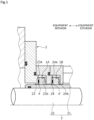
- a segment seal according to a first embodiment of the present invention will be described with reference to FIG. 1 to FIG. 6 .
- the left side on a paper plane of FIG. 1 is referred to as an equipment interior side of rotating equipment to which the segment seal is applied
- the right side on a paper plane of FIG. 1 is referred to as an equipment exterior side thereof.
- the equipment interior side will be described as a sealed fluid side (i.e., the high-pressure side)
- the equipment exterior side will be described as an atmosphere side (i.e., the low-pressure side).
- segment seals 1A, 1B of a first embodiment are housed to seal an annular space between a housing 2 and a rotating shaft 3 extending through the housing 2.
- the rotating shaft 3 of this embodiment includes a shaft body 32 made of a metal such as stainless steel, and a sleeve 31 made of a metal such as stainless steel fitted onto the shaft body 32.
- the segment seals 1A, 1B in a pair are configured as a tandem seal such that they are disposed side by side in an axial direction in an annular space between the housing 2 and the rotating shaft 3.
- the pair of segment seals 1A, 1B the one disposed on the equipment interior side will be referred to as the segment seal 1A, and the other disposed on the equipment exterior side will be referred to as the segment seal 1B.
- the housing 2 is provided with a first annular recess 23 and a second annular recess 24 arranged side by side in the axial direction for housing the segment seals 1A, 1B.
- the housing 2 has a divided structure composed of a plurality of members, however, it may be composed of a single member.
- a spring 4 is disposed as a biasing member between an end face 23a on the equipment interior side defining the first annular recess 23 and the segment seal 1A.
- the segment seal 1A is biased by the spring 4 toward an end face 23b as an installation surface on the equipment exterior side defining the first annular recess 23.
- a spring 4' is disposed as a biasing member between an end face 24a on the equipment interior side defining the second annular recess 24 and the segment seal 1B.
- the segment seal 1B is biased by the spring 4' toward an end face 24b as the installation surface on the equipment exterior side defining the second annular recess 24.
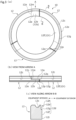
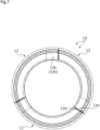
- the circumferential end faces 14e of the resin segments 14 are in contact with each other.
- the resin segments 14 each cover the gap in the axial direction between the circumferential end face 12p on the equipment exterior side in the main body of the segment 12 and the circumferential end face 12q of the protruding portion 12b. Accordingly, the sealed fluid on the equipment interior side is less likely to flow in the axial direction toward the equipment exterior side.
- an equipment-exterior-side end face 14g of the resin segment 14 is in contact with the end face 23b of the housing 2, and the sealed fluid on the equipment interior side is thus less likely to flow in the radial direction toward the equipment exterior side.
- sealing here is not limited to complete sealing between the equipment interior side and the equipment exterior side, but also includes that the movement of fluid between the equipment interior side and the equipment exterior side is restricted, in other words, that the movement of fluid between the equipment interior side and the equipment exterior side is partially allowed.
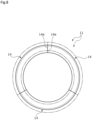
- the base ring 10 contracts slightly overall toward the center, reducing the gap between the circumferential end faces 12p, 12q.
- the resin ring 11 contracts overall toward the center with the circumferential end faces 14e being in contact with each other. For the amount of overall contraction, the resin ring 11 is greater.
- the shape of the rings in the one temperature range at room temperature is illustrated by a two-dot dashed line.
- the resin ring 11 thermally contracts to a greater extent than the rotating shaft 3. Accordingly, the inner peripheral surface of the resin ring 11 is arranged apart radially outward from the sleeve 31 by a slight distance L2' (L2>L2'). The distance L2' is smaller than the distance L1' (L1'>L2').
- the gap g' between the segment seal 1A and the rotating shaft 3 is sealed by the slight gap between the resin ring 11 and the sleeve 31.
- the base ring 10 performs a sealing function
- the resin ring 11 disposed side by side with the base ring 10 performs a sealing function, such that the sealing function can be performed in a wide range of temperatures.
- the resin ring 11 can be fixed to the highly rigid base ring 10 to stabilize the shape of the resin ring 11.
- the resin ring 11 also has higher toughness than the base ring 10. Accordingly, even if the resin ring 11 contracts, the axial portion 14b as the engagement portion with the base ring 10 is less likely to be damaged.
- the resin ring 11 can be thermally deformed radially inward to a greater extent than the base ring 10 to ensure sealing performance due to the difference in thermal expansion. Additionally, the resin ring 11 can follow the centering function of the base ring 10, such that the resin ring 11 can perform a sealing function even at the low temperature range.
- a gap in the axial direction may be formed between the radially inner portion 12f of the base ring 10 and the equipment-exterior-side end face 14h of the resin ring 11, from which leakage can be prevented for the following reasons.
- the resin ring 11 is fixed to the base ring 10, and the resin segments 14 are in contact with each other in the circumferential direction.
- the resin ring 11 can be thermally deformed radially inward in accordance with changes in the operating temperature environment to reliably adjust the gap between the resin ring 11 and the sleeve 31.
- a position of the axial portion 14b of the resin ring 11 is restricted by the base ring 10, and the radial portion 14a is slidable in the radial direction relative to the base ring 10.
- the axial portion 14b is fitted and bonded to the step defined by the radially outer portion 12e and the connecting portion 12g of the end face 12d in the base ring 10
- the radial portion 14a is not bonded to the radially inner portion 12f of the end face 12d in the base ring 10
- the inner peripheral end portion axial surface 14f of the radial portion 14a and an opposing surface 12i of the radially inner portion 12f as the axial surface of the segments 12 opposing the inner peripheral end portion axial surface 14f are each formed into a plane extending in the radial direction. Accordingly, the radial portion 14a can be thermally deformed in accordance with changes in temperature environment, and can be reliably slid radially inward.
- the resin ring 11 is constituted by the plurality of resin segments 14 segmented in the circumferential direction, and the resin segments 14 are fixed to the segments 12 constituting the base ring 10. Accordingly, when the rotating shaft 3 moves in the radial direction due to shaft vibration or the like, the resin segments 14 can follow the movement in the radial direction of the rotating shaft 3 together with the segments 12 of the base ring 10.
- the base ring 10 to which the resin ring 11 is fixed is held in an annular shape by the annular garter spring 13 arranged around the outer peripheral surfaces of the rigid segments 12, no elastic force of the garter springs 13 acts on the resin ring 11, and the resin ring 11 can be prevented from being deformed.
- segment seals 1A, 1B are pressed against the end faces 23b, 24b of the housing 2 by the springs 4, 4' that bias the base ring 10 in the axial direction. Accordingly, the segment seals 1A, 1B can be held in pressure contact with the end faces 23b, 24b of the housing 2 by the springs 4, 4', and the biasing force of the springs 4, 4' acts on the base ring 10, such that no biasing force of the springs 4, 4' acts directly on the resin ring 11, and the resin ring 11 can be prevented from being deformed.
- the resin rings 11 of the segment seals 1A, 1B are in contact with the end faces 23b, 24b of the housing 2, providing high sliding properties, such that when the rotating shaft 3 moves in the radial direction due to shaft vibration or the like, the segment seals 1A, 1B can smoothly follow that movement.
- the resin ring 11 is disposed on the equipment exterior side that is the low-pressure side, the resin ring 11 is less susceptible to the influence of the fluid pressure of the sealed fluid on the equipment interior side that is the high-pressure side. Specifically, resin is more susceptible to deformation due to temperature and pressure than carbon, and when the segment seals 1A, 1B are made of resin, they may be deformed by fluid pressure, spring pressure, garter spring pressure, changes in temperature, or the like and may have reduced sealing function or fail to function.
- the base of the segment seals 1A, 1B is composed of the carbon base ring 10, to which the resin ring 11 is attached on the low-pressure side, such that they are less susceptible to deformation due to pressure and temperature, and can maintain high followability in the radial direction even in the high-pressure or low-temperature environment.
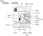
- a segment seal 40 of the second embodiment includes a base ring 410 and a resin ring 411.
- the base ring 410 has an annular fitting recess 412 on the equipment exterior side into which the resin ring 411 can be fitted.
- an outer-diameter-side portion 412a is recessed on the equipment interior side to a greater extent than an inner-diameter-side portion 412b.
- the fitting recess 412 is formed into a generally inverted L-shape in cross section.
- the base ring 410 has an annular portion 410a formed in the outer-diameter-side portion 412a of the fitting recess 412.
- the fitting recess 412 is defined by a surface 410h extending in the axial direction, a surface 410i extending radially inward from the surface 410h, a surface 410j extending from the surface 410i toward the equipment exterior side in the axial direction, and a surface 410k extending radially inward from the surface 410j.
- the resin ring 411 has a radial portion 414a as an inner-diameter-side portion and an axial portion 414b as an outer diameter portion, and is formed into a generally inverted L-shape in cross section.
- An outer peripheral surface 411h of the resin ring 411 is disposed opposite the surface 410h.
- an end face 411i on the equipment interior side and on the outer diameter side is disposed opposite the surface 410i
- an intermediate peripheral surface 411j is disposed opposite the surface 410j
- an end face 411k on the equipment interior side and on the inner diameter side is disposed opposite the surface 410k.
- the resin ring 411 may be attached to the fitting recess 412 due to the difference in thermal expansion coefficient between the resin ring 411 and the base ring 410 or may be press-fitted into the fitting recess 412.
- the fixing method is not limited and may be adhesion, fitting, or the like.
- the resin ring 411 is at least partially fixed to the base ring 410, and an equipment-exterior-side end face 411m of the resin ring 411 is in contact with the end face 23b of the housing 2 in the axial direction.
Landscapes
- Engineering & Computer Science (AREA)
- General Engineering & Computer Science (AREA)
- Mechanical Engineering (AREA)
- Sealing Devices (AREA)
- Sealing With Elastic Sealing Lips (AREA)
Applications Claiming Priority (2)
| Application Number | Priority Date | Filing Date | Title |
|---|---|---|---|
| JP2022132612 | 2022-08-23 | ||
| PCT/JP2023/030018 WO2024043212A1 (ja) | 2022-08-23 | 2023-08-21 | セグメントシール |
Publications (1)
| Publication Number | Publication Date |
|---|---|
| EP4579108A1 true EP4579108A1 (en) | 2025-07-02 |
Family
ID=90013297
Family Applications (1)
| Application Number | Title | Priority Date | Filing Date |
|---|---|---|---|
| EP23857323.2A Withdrawn EP4579108A1 (en) | 2022-08-23 | 2023-08-21 | Segment seal |
Country Status (4)
| Country | Link |
|---|---|
| EP (1) | EP4579108A1 (https=) |
| JP (1) | JPWO2024043212A1 (https=) |
| CN (1) | CN119677979A (https=) |
| WO (1) | WO2024043212A1 (https=) |
Families Citing this family (1)
| Publication number | Priority date | Publication date | Assignee | Title |
|---|---|---|---|---|
| US12516609B2 (en) | 2024-06-14 | 2026-01-06 | Pratt & Whitney Canada Corp. | Serviceable propeller shaft zero air gap seal |
Family Cites Families (6)
| Publication number | Priority date | Publication date | Assignee | Title |
|---|---|---|---|---|
| JPS5853864U (ja) * | 1981-10-07 | 1983-04-12 | 株式会社日立製作所 | 水車の軸封水装置 |
| JPH0614131Y2 (ja) * | 1988-04-28 | 1994-04-13 | エヌオーケー株式会社 | シールリング |
| JP3945661B2 (ja) * | 1995-01-10 | 2007-07-18 | 株式会社阪上製作所 | 回転用シール装置 |
| JP2005201314A (ja) * | 2004-01-14 | 2005-07-28 | Tanken Seal Seiko Co Ltd | セグメントシール |
| US8690534B1 (en) * | 2009-06-08 | 2014-04-08 | Curtiss-Wright Electro-Mechanical Corporation | Backup seals in rotary pumps |
| WO2019031377A1 (ja) | 2017-08-07 | 2019-02-14 | イーグル工業株式会社 | セグメントシール |
-
2023
- 2023-08-21 JP JP2024542812A patent/JPWO2024043212A1/ja active Pending
- 2023-08-21 EP EP23857323.2A patent/EP4579108A1/en not_active Withdrawn
- 2023-08-21 WO PCT/JP2023/030018 patent/WO2024043212A1/ja not_active Ceased
- 2023-08-21 CN CN202380059064.6A patent/CN119677979A/zh active Pending
Also Published As
| Publication number | Publication date |
|---|---|
| CN119677979A (zh) | 2025-03-21 |
| WO2024043212A1 (ja) | 2024-02-29 |
| JPWO2024043212A1 (https=) | 2024-02-29 |
Similar Documents
| Publication | Publication Date | Title |
|---|---|---|
| EP3517807B1 (en) | Single seal ring stuffing box | |
| CN105736701B (zh) | 拱形结合环形密封件及具有该环形密封件的环密封系统 | |
| EP3450804B1 (en) | Mechanical seal | |
| US7611151B2 (en) | Mechanical seal with thermally stable mating ring | |
| WO2018105505A1 (ja) | しゅう動部品 | |
| US20140265151A1 (en) | Circumferential Seal with Ceramic Runner | |
| US9464535B2 (en) | Stationary part sealing structure | |
| EP4579108A1 (en) | Segment seal | |
| EP3159582B1 (en) | Shaft seal device and rotary machine | |
| US9945241B2 (en) | Sealing element of an axial turbomachine | |
| CN108317164B (zh) | 用于旋转轴的组合轴承和密封件组件 | |
| US11287043B2 (en) | High clearance seal assembly | |
| CN108413041A (zh) | 浮动环机械密封件 | |
| JP2002122243A (ja) | 分割型シール | |
| US10619501B2 (en) | Sealing element | |
| US10082172B2 (en) | Plain bearing and/or systems incorporating such bearings | |
| WO2013096160A1 (en) | Pumping seal having projections for axially positioning a biasing member | |
| JP2017133571A (ja) | 密封装置 | |
| US10359048B2 (en) | Sealing system and turbopump comprising such a system | |
| US20260049661A1 (en) | Mechanical seal | |
| JP2024110622A (ja) | 密封装置および軸受 | |
| CN108413040A (zh) | 唇形机械密封装置 | |
| JP2019094939A (ja) | 密封構造 |
Legal Events
| Date | Code | Title | Description |
|---|---|---|---|
| STAA | Information on the status of an ep patent application or granted ep patent |
Free format text: STATUS: THE INTERNATIONAL PUBLICATION HAS BEEN MADE |
|
| PUAI | Public reference made under article 153(3) epc to a published international application that has entered the european phase |
Free format text: ORIGINAL CODE: 0009012 |
|
| STAA | Information on the status of an ep patent application or granted ep patent |
Free format text: STATUS: REQUEST FOR EXAMINATION WAS MADE |
|
| 17P | Request for examination filed |
Effective date: 20250213 |
|
| AK | Designated contracting states |
Kind code of ref document: A1 Designated state(s): AL AT BE BG CH CY CZ DE DK EE ES FI FR GB GR HR HU IE IS IT LI LT LU LV MC ME MK MT NL NO PL PT RO RS SE SI SK SM TR |
|
| STAA | Information on the status of an ep patent application or granted ep patent |
Free format text: STATUS: THE APPLICATION HAS BEEN WITHDRAWN |
|
| DAV | Request for validation of the european patent (deleted) | ||
| DAX | Request for extension of the european patent (deleted) | ||
| 18W | Application withdrawn |
Effective date: 20251103 |