EP4579042A2 - Elektrowerkzeug - Google Patents
Elektrowerkzeug Download PDFInfo
- Publication number
- EP4579042A2 EP4579042A2 EP24211322.3A EP24211322A EP4579042A2 EP 4579042 A2 EP4579042 A2 EP 4579042A2 EP 24211322 A EP24211322 A EP 24211322A EP 4579042 A2 EP4579042 A2 EP 4579042A2
- Authority
- EP
- European Patent Office
- Prior art keywords
- connecting rod
- power tool
- handle
- working head
- axis
- Prior art date
- Legal status (The legal status is an assumption and is not a legal conclusion. Google has not performed a legal analysis and makes no representation as to the accuracy of the status listed.)
- Pending
Links
Images








Classifications
-
- E—FIXED CONSTRUCTIONS
- E01—CONSTRUCTION OF ROADS, RAILWAYS, OR BRIDGES
- E01H—STREET CLEANING; CLEANING OF PERMANENT WAYS; CLEANING BEACHES; DISPERSING OR PREVENTING FOG IN GENERAL CLEANING STREET OR RAILWAY FURNITURE OR TUNNEL WALLS
- E01H5/00—Removing snow or ice from roads or like surfaces; Grading or roughening snow or ice
- E01H5/04—Apparatus propelled by animal or engine power; Apparatus propelled by hand with driven dislodging or conveying levelling elements, conveying pneumatically for the dislodged material
- E01H5/08—Apparatus propelled by animal or engine power; Apparatus propelled by hand with driven dislodging or conveying levelling elements, conveying pneumatically for the dislodged material dislodging essentially by driven elements
- E01H5/09—Apparatus propelled by animal or engine power; Apparatus propelled by hand with driven dislodging or conveying levelling elements, conveying pneumatically for the dislodged material dislodging essentially by driven elements the elements being rotary or moving along a closed circular path, e.g. rotary cutter, digging wheels
- E01H5/098—Apparatus propelled by animal or engine power; Apparatus propelled by hand with driven dislodging or conveying levelling elements, conveying pneumatically for the dislodged material dislodging essentially by driven elements the elements being rotary or moving along a closed circular path, e.g. rotary cutter, digging wheels about horizontal or substantially horizontal axises perpendicular or substantially perpendicular to the direction of clearing
-
- B—PERFORMING OPERATIONS; TRANSPORTING
- B25—HAND TOOLS; PORTABLE POWER-DRIVEN TOOLS; MANIPULATORS
- B25F—COMBINATION OR MULTI-PURPOSE TOOLS NOT OTHERWISE PROVIDED FOR; DETAILS OR COMPONENTS OF PORTABLE POWER-DRIVEN TOOLS NOT PARTICULARLY RELATED TO THE OPERATIONS PERFORMED AND NOT OTHERWISE PROVIDED FOR
- B25F5/00—Details or components of portable power-driven tools not particularly related to the operations performed and not otherwise provided for
- B25F5/02—Construction of casings, bodies or handles
Definitions
- the present application relates to the technical field of tools and, in particular, to a power tool.
- Power tools are more environmentally friendly than engine-powered tools, leading to wide use of the power tools. For example, a snowfall causes snow accumulation in yards and on roads, making travel and activities inconvenient for people. The removal of the snow with shovels and brooms is too inefficient. Snow on an arterial road is generally removed by snow removal equipment. Existing snow removal equipment generally shovels up the snow with its snow shovel and rotates the auger to throw the shoveled-up snow outside. The auger is generally configured to be spiral, causing the shoveled-up snow to accumulate at the roadside.
- a handle of a snow shovel is not in accord with use habits of users. It is inconvenient for a user to push and use the snow shovel to remove snow. Additionally, the snow shovel is relatively heavy, so it is more laborious for the user to use the snow shovel for a long period of time.
- a power tool includes: an operation portion including a first handle for the user to grip; a working head drivable to work; a connecting rod connecting the first handle to the working head; and a battery pack configured to power the power tool.
- the first handle is disposed at the rear end of the connecting rod, and the first handle and the battery pack are disposed vertically along a direction perpendicular to the axis of the connecting rod.
- an extension direction of the first handle forms a first included angle with the walking direction of the power tool, wherein the first included angle is greater than or equal to 30 degrees and less than or equal to 90 degrees.
- a lower edge of the first handle forms a second included angle with the axis of the connecting rod, where the second included angle is greater than or equal to 45 degrees and less than or equal to 90 degrees.
- the first handle further includes a grip trigger, and the height difference between the central position of the grip trigger and the axis of the connecting rod is less than or equal to 200 mm.
- the center of a grip of the first handle is disposed on the upper side of the axis of the connecting rod, and the battery pack is disposed on the lower side of the axis of the connecting rod.
- the battery pack is detachably connected to the connecting rod and is mounted to the connecting rod along a direction parallel to the connecting rod.
- the battery pack has a first length parallel to the connecting rod and a second length perpendicular to the connecting rod, where the first length is greater than the second length.
- the power tool further includes a second handle disposed on the upper side of the connecting rod.
- the second handle is disposed between the first handle and the working head, and when the included angle between the axis of the connecting rod and the walking direction of the power tool is 45 degrees, the height difference between the second handle and the central position of the first handle is less than or equal to 200 mm.
- the operation portion further includes a speed adjustment assembly configured to adjust a working speed of the power tool.
- the battery pack when the power tool is placed on the ground with the working head and the battery pack both touching the ground, the battery pack forms a third included angle with the ground, where the third included angle is less than or equal to 30 degrees.
- the connecting rod includes a first connecting rod connected to the working head and a second connecting rod connected to the operation portion, the first connecting rod and the second connecting rod are connected to each other through a connecting assembly, the connecting assembly is a foldable assembly, and the connecting assembly is folded so that the connecting rod is folded, causing the power tool to be in a folded state.
- the uppermost end of the working head away from the axis of the connecting rod is connected to an end of the first connecting rod away from the working head to form a first straight line, and the center of the first handle is located between the first straight line and the first connecting rod.
- the first handle further includes a grip trigger, and when the included angle between the connecting rod and the direction in which the power tool is pushed by the user is 45 degrees, the height difference between the central position of the grip trigger and the axis of the connecting rod is less than or equal to 200 mm.
- the term "and/or” is a kind of association relationship describing the relationship between associated objects, which means that there can be three kinds of relationships.
- a and/or B can indicate that A exists alone, A and B exist simultaneously, and B exists alone.
- the character "/" in this application generally indicates that the contextual associated objects belong to an "and/or” relationship.
- a relative term (such as “about”, “approximately”, and “substantially) used in conjunction with quantity or condition includes a stated value and has a meaning dictated by the context.
- the relative term includes at least a degree of error associated with the measurement of a particular value, a tolerance caused by manufacturing, assembly, and use associated with the particular value, and the like.
- Such relative term should also be considered as disclosing the range defined by the absolute values of the two endpoints.
- the relative term may refer to plus or minus of a certain percentage (such as 1%, 5%, 10%, or more) of an indicated value. A value that did not use the relative term should also be disclosed as a particular value with a tolerance.
- “substantially” when expressing a relative angular position relationship may refer to adding or subtracting a certain degree (such as 1 degree, 5 degrees, 10 degrees or more) to the indicated angle.
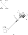
- FIG. 1 illustrates a power tool.
- the power tool may specifically be a pole power tool, for example, a snow shovel 100, a string trimmer, a pruner, pruning shears, or a wall grinder.
- a snow shovel 100 is described below as an example.
- FIG. 1 illustrates a snow shovel 100 for a user to remove snow.
- the snow shovel 100 includes an operation portion 10, a working head 20, a connecting rod 30, and a battery pack 40.
- the operation portion 10 includes a first handle 11.
- the first handle 11 is used as a main handle for the user to grip.
- the working head 20 is driven to work, for example, to remove snow.
- the connecting rod 30 connects the first handle 11 to the working head 20.
- the operation portion 10 further includes a battery pack mounting portion 12 on which the battery pack 40 is mounted. This battery pack 40 is configured to power the snow shovel 100.
- a front side, a rear side, a left side, a right side, an upper side, and a lower side are defined as shown in FIG. 1 .
- the front side, the rear side, the left side, the right side, the upper side, and the lower side are defined based on the connecting rod 30.
- the connecting rod 30 may be made of aluminum, thereby reducing the overall weight of the snow shovel 100 and making the snow shovel 100 convenient for the user to use.
- the first handle 11 is disposed at the rear end of the connecting rod 30.
- the first handle 11 and the battery pack 40 are disposed vertically along a direction perpendicular to the axis 301 of the connecting rod 30. That is, along the direction perpendicular to the axis 301 of the connecting rod 30, the first handle 11 and the battery pack 40 have a vertical disposing relationship.
- the first handle 11 is disposed on the upper side of the battery pack 40, or the battery pack 40 is disposed on the upper side of the first handle 11. As shown in FIG.
- the first handle 11 is disposed on the upper side of the battery pack 40, and the first handle 11 and the battery pack 40 are disposed on two sides of the connecting rod 30 respectively to be connected to the connecting rod 30.
- the center of a grip of the first handle 11 is disposed on the upper side of the axis 301 of the connecting rod 30, and the battery pack 40 is disposed on the lower side of the axis 301 of the connecting rod 30.
- the operation portion 10 further includes a speed adjustment assembly 13 configured to adjust a working speed of the snow shovel 100.
- the snow shovel 100 may have two working speeds: a low speed and a high speed.
- the speed adjustment assembly 13 is operated so that the working speed of the snow shovel 100 is switched to the low speed or the high speed.
- the snow shovel 100 may have multiple working speeds such as a third speed and a fourth speed.
- the specific number of speeds of the snow shovel 100 is not limited in the present application.
- the operation portion 10 further includes a switch assembly 14 configured to control the start or stop of the snow shovel 100.
- Both the speed adjustment assembly 13 and the switch assembly 14 are disposed on the operation portion 10 so that it is convenient for the user to control the start and stop of the snow shovel 100 while gripping the first handle 11 and adjust the working speed of the snow shovel 100 at any time.
- a D-shaped space is formed at the position in the operation portion 10 for the user to grip and is in accord with the shape of the hand of the user gripping the first handle 11.
- an extension direction of the first handle 11 forms a first included angle A with the walking direction of the power tool.
- the walking direction is the direction the working head 20 moves towards when the operation portion 10 is pushed by a user.
- the extension direction of the first handle 11 refers to the centerline of the handle 11.
- the first included angle A is greater than or equal to 30 degrees and less than or equal to 90 degrees.
- the first included angle A is 35 degrees.
- the first included angle A is 45 degrees.
- the first included angle A is 60 degrees. As shown in FIG.
- the first handle 11 forms a second included angle B with the connecting rod 30.
- the second included angle B is between a lower edge of the first handle 11 and the axis 301 of the connecting rod 30.
- the second included angle B is greater than or equal to 45 degrees and less than or equal to 90 degrees.
- the second included angle B is 50 degrees.
- the second included angle B is 60 degrees.
- the second included angle B is 75 degrees.
- the first handle 11 further includes a grip trigger 111.
- the grip trigger 111 is specifically gripped by the user when the snow shovel 100 is used.
- the height difference H1 between the central position of the grip trigger 111 and the axis 301 of the connecting rod 30 is less than or equal to 200 mm.
- the central position of the grip trigger 111 may be disposed below the axis 301 of the connecting rod 30. In this case, the height difference H1 between the central position of the grip trigger 111 and the axis 301 of the connecting rod 30 is less than or equal to 50 mm.
- the central position of the grip trigger 111 may be below the axis 301 of the connecting rod 30, the grip trigger 111 is at least partially disposed below the axis 301 of the connecting rod 30, and the range of the central position of the grip trigger 111 below the axis 301 of the connecting rod 30 does not exceed 50 mm.
- the central position of the grip trigger 111 may be parallel to the axis 301 of the connecting rod 30 or may be disposed above the axis 301 of the connecting rod 30, and the range of the central position of the grip trigger 111 above the axis 301 of the connecting rod 30 does not exceed 200 mm.
- the grip trigger 111 is at least partially disposed above the axis 301 of the connecting rod 30 and is parallel to the axis 301 of the connecting rod 30.
- the included angle between the first handle 11 and the direction in which the power tool is pushed by the user, the included angle between the first handle 11 and the connecting rod 30, and the height difference H1 between the axis 301 of the connecting rod 30 and the grip trigger 111 which is specifically gripped by the user when using the snow shovel 100 are configured, which each allow the user to push the snow shovel 100 with less effort. Thus, it is more convenient for the user to push and use the snow shovel 100.
- a second handle 50 is further disposed on the snow shovel 100 and is used as an auxiliary handle.
- the second handle 50 is disposed between the first handle 11 and the working head 20 and disposed on the connecting rod 30.
- the second handle 50 is also disposed on the upper side of the connecting rod 30.
- the user can grip both the first handle 11 and the second handle 50 simultaneously.
- the included angle between the snow shovel 100 and the ground is 45 degrees, the height difference H2 between the central position of the first handle 11 and the central position of the second handle 50 is less than or equal to 200 mm.
- the range of the central position of the second handle 50 below the central position of the first handle 11 is less than or equal to 200 mm.
- lighting devices are mounted on the first handle 11 and/or the second handle 50.
- the lighting devices can assist the user in clearly seeing the operation portion 10 for operation and assist the user in clearly seeing a road surface so that it is convenient for the user to use the snow shovel 100.
- a respective one of the lighting devices may be disposed at any position on the first handle 11 or the second handle 50.
- the positions of the lighting devices are not limited in the present application.
- the lighting devices may be powered by the battery pack 40.
- the lighting devices may be lighting devices that can store electricity. After being charged through an external power supply, the lighting devices are mounted on the first handle 11 and/or the second handle 50.
- the lighting devices may be powered in other manners. The manner in which the lighting devices are powered is not limited in the present application.
- the battery pack 40 is detachably connected to the connecting rod 30.
- the battery pack 40 is mounted to the connecting rod 30 along a direction parallel to the connecting rod 30. That is, the battery pack 40 is mounted on the battery pack mounting portion 12 of the operation portion 10 along the direction parallel to the connecting rod 30 and disposed on the lower side of the connecting rod 30.
- the battery pack 40 is parallel to the connecting rod 30.
- the battery pack 40 has a first length 41 parallel to the connecting rod 30 and a second length 42 perpendicular to the connecting rod 30.
- the first length 41 is greater than the second length 42. That is, a relatively small surface of the battery pack 40 is mounted to the battery pack mounting portion 12, and a relatively large surface of the battery pack 40 is parallel to the connecting rod 30.
- the center of gravity of the battery pack 40 is higher than the central position of the connecting rod 30.
- the gravity of the battery pack 40 can be shared by the connecting rod 30.
- the battery pack 40 forms a third included angle C with the ground.
- the included angle C is between a lower edge of the battery pack 40 and the ground.
- the third included angle C is less than or equal to 30 degrees. Since the included angle between the battery pack 40 and the ground is relatively small, a relatively large area on the battery pack 40 is in contact with the ground. Thus, when the user stops using the snow shovel 100 and releases it, the battery pack 40 is less likely to impact the ground and be damaged.
- the connecting rod 30 includes a first connecting rod 31 and a second connecting rod 32.
- the first connecting rod 31 and the second connecting rod 32 are connected to each other through a connecting assembly 33 to form the connecting rod 30.
- the first connecting rod 31 is connected to the working head 20, and the second connecting rod 32 is connected to the operation portion 10.
- the connecting assembly 33 is foldable.
- the connecting assembly 33 is folded so that the connecting rod 30 is folded, causing the snow shovel 100 to be in a folded state.
- the snow shovel shown in FIG. 6 may be the snow shovel 100 shown in FIG. 1 with the second handle 20 removed.
- the snow shovel shown in FIG. 6 may be a snow shovel in another example.
- both the first connecting rod 31 and the second connecting rod 32 may be linear connecting rods. That is, the connecting rod 30 is a linear connecting rod. Then, the axis 301 of the connecting rod 30 is a linear axis.
- the connecting rod 30 may be constituted by a curved connecting rod and a linear connecting rod, and the axis 301 of the connecting rod 30 may include a curved axis and a linear axis.
- the portion of the connecting rod 30 connected to the operation portion 10 is the linear connecting rod while the portion of the connecting rod 30 connected to the working head 20 is the curved connecting rod. That is, the second connecting rod 32 may be the linear connecting rod, and the first connecting rod 31 may be the curved connecting rod.
- the axis 301 of the connecting rod 30 may be linear or may be partially linear.
- the linear connecting rod 30 is used as an example for description in the present application.
- the uppermost end 201 of the working head 20 away from the axis 301 of the connecting rod 30 is connected to an end 311 of the first connecting rod 31 away from the working head 20 to form a first straight line 34. That is, the uppermost end 201 of the working head 20 in the direction perpendicular to the axis 301 of the connecting rod 30 is connected to the end 311 of the first connecting rod 31 that is not connected to the working head 20 such that the first straight line 34 is formed.
- the center of the first handle 11 is located between the first straight line 34 and the first connecting rod 31.
- the first straight line 34, the first connecting rod 31, and the working head 20 form a triangular region M.
- the center of the first handle 11 is located within this triangular region M.
- a preset projection of the second connecting rod 32 and the operation portion 10 is formed on a plane N parallel to the axis 301 of the connecting rod 30 and perpendicular to the working head 20. Additionally, the length of the first connecting rod 31 is greater than or equal to the length of this preset projection.
- the distance H3 between the center of the first handle 11 and the axis 301 of the first connecting rod 31 is less than or equal to 270 mm.
- the first handle 11 may abut against the first connecting rod 31.
- the first handle 11 is in contact with the first connecting rod 31.
- the distance between the center of the first handle 11 and the axis 301 of the first connecting rod 31 is minimized.
- the first handle 11 may not be in contact with the first connecting rod 31 and the first handle 11 is located above the first connecting rod 31 as long as the center of the first handle 11 only needs to be located within the triangular region M.
Landscapes
- Engineering & Computer Science (AREA)
- Architecture (AREA)
- Civil Engineering (AREA)
- Structural Engineering (AREA)
- Mechanical Engineering (AREA)
- Cleaning Of Streets, Tracks, Or Beaches (AREA)
- Portable Power Tools In General (AREA)
Applications Claiming Priority (3)
| Application Number | Priority Date | Filing Date | Title |
|---|---|---|---|
| CN202323602873.3U CN221480679U (zh) | 2023-12-27 | 2023-12-27 | 电动工具 |
| CN202311838640.5A CN120244879A (zh) | 2023-12-27 | 2023-12-27 | 电动工具 |
| CN202323596144.1U CN222594715U (zh) | 2023-12-27 | 2023-12-27 | 扫雪铲 |
Publications (2)
| Publication Number | Publication Date |
|---|---|
| EP4579042A2 true EP4579042A2 (de) | 2025-07-02 |
| EP4579042A3 EP4579042A3 (de) | 2025-08-27 |
Family
ID=93455544
Family Applications (1)
| Application Number | Title | Priority Date | Filing Date |
|---|---|---|---|
| EP24211322.3A Pending EP4579042A3 (de) | 2023-12-27 | 2024-11-07 | Elektrowerkzeug |
Country Status (2)
| Country | Link |
|---|---|
| US (1) | US20250215652A1 (de) |
| EP (1) | EP4579042A3 (de) |
Family Cites Families (4)
| Publication number | Priority date | Publication date | Assignee | Title |
|---|---|---|---|---|
| US9414540B2 (en) * | 2010-03-24 | 2016-08-16 | Aero-Flex Technologies, Inc. | Oriented trimmer line |
| AT14057U1 (de) * | 2014-01-17 | 2015-03-15 | Sonneck Ges M B H | Schneefräse |
| DE102015207151A1 (de) * | 2015-04-20 | 2016-10-20 | Robert Bosch Gmbh | Befestigungsmittel für Handwerkzeugmaschine |
| US20230112033A1 (en) * | 2017-08-07 | 2023-04-13 | Nanjing Chervon Industry Co., Ltd. | Grass trimming head and grass trimmer having the same |
-
2024
- 2024-11-06 US US18/938,536 patent/US20250215652A1/en active Pending
- 2024-11-07 EP EP24211322.3A patent/EP4579042A3/de active Pending
Also Published As
| Publication number | Publication date |
|---|---|
| US20250215652A1 (en) | 2025-07-03 |
| EP4579042A3 (de) | 2025-08-27 |
Similar Documents
| Publication | Publication Date | Title |
|---|---|---|
| US20260062881A1 (en) | Snow thrower | |
| US10485166B2 (en) | Power tool | |
| EP3821692B1 (de) | Rasenmäher | |
| US20220183241A1 (en) | Garden blower | |
| CN101817106A (zh) | 蓄电池驱动的手操纵式工作器械 | |
| JP2014148950A (ja) | 電動ブロワ | |
| CN106258180A (zh) | 手推式割草机 | |
| EP3302019B1 (de) | Hocheffizientes rasenpflegewerkzeug | |
| CN207269427U (zh) | 修枝机 | |
| EP4579042A2 (de) | Elektrowerkzeug | |
| CN217644222U (zh) | 一种割草机 | |
| US20230371449A1 (en) | Garden blower | |
| CN221480679U (zh) | 电动工具 | |
| CN105673528B (zh) | 一种电动工具 | |
| CN222594715U (zh) | 扫雪铲 | |
| CN207505508U (zh) | 修枝机 | |
| CN208707470U (zh) | 一种多供电式电动工具 | |
| AU2015101657B4 (en) | An electric tool | |
| CN204327537U (zh) | 一种电动工具 | |
| CN120244879A (zh) | 电动工具 | |
| CN207505510U (zh) | 修枝机 | |
| CN117337685A (zh) | 一种手推式动力工具 | |
| EP4298887A1 (de) | Mäher | |
| CN117356248A (zh) | 一种割草机 | |
| CN208079802U (zh) | 一种新型割草机 |
Legal Events
| Date | Code | Title | Description |
|---|---|---|---|
| PUAI | Public reference made under article 153(3) epc to a published international application that has entered the european phase |
Free format text: ORIGINAL CODE: 0009012 |
|
| STAA | Information on the status of an ep patent application or granted ep patent |
Free format text: STATUS: THE APPLICATION HAS BEEN PUBLISHED |
|
| AK | Designated contracting states |
Kind code of ref document: A2 Designated state(s): AL AT BE BG CH CY CZ DE DK EE ES FI FR GB GR HR HU IE IS IT LI LT LU LV MC ME MK MT NL NO PL PT RO RS SE SI SK SM TR |
|
| PUAL | Search report despatched |
Free format text: ORIGINAL CODE: 0009013 |
|
| AK | Designated contracting states |
Kind code of ref document: A3 Designated state(s): AL AT BE BG CH CY CZ DE DK EE ES FI FR GB GR HR HU IE IS IT LI LT LU LV MC ME MK MT NL NO PL PT RO RS SE SI SK SM TR |
|
| RIC1 | Information provided on ipc code assigned before grant |
Ipc: E01H 5/09 20060101AFI20250723BHEP |
|
| STAA | Information on the status of an ep patent application or granted ep patent |
Free format text: STATUS: REQUEST FOR EXAMINATION WAS MADE |
|
| 17P | Request for examination filed |
Effective date: 20260203 |