EP4579042A2 - Power tool - Google Patents
Power tool Download PDFInfo
- Publication number
- EP4579042A2 EP4579042A2 EP24211322.3A EP24211322A EP4579042A2 EP 4579042 A2 EP4579042 A2 EP 4579042A2 EP 24211322 A EP24211322 A EP 24211322A EP 4579042 A2 EP4579042 A2 EP 4579042A2
- Authority
- EP
- European Patent Office
- Prior art keywords
- connecting rod
- power tool
- handle
- working head
- axis
- Prior art date
- Legal status (The legal status is an assumption and is not a legal conclusion. Google has not performed a legal analysis and makes no representation as to the accuracy of the status listed.)
- Pending
Links
Images








Classifications
-
- E—FIXED CONSTRUCTIONS
- E01—CONSTRUCTION OF ROADS, RAILWAYS, OR BRIDGES
- E01H—STREET CLEANING; CLEANING OF PERMANENT WAYS; CLEANING BEACHES; DISPERSING OR PREVENTING FOG IN GENERAL CLEANING STREET OR RAILWAY FURNITURE OR TUNNEL WALLS
- E01H5/00—Removing snow or ice from roads or like surfaces; Grading or roughening snow or ice
- E01H5/04—Apparatus propelled by animal or engine power; Apparatus propelled by hand with driven dislodging or conveying levelling elements, conveying pneumatically for the dislodged material
- E01H5/08—Apparatus propelled by animal or engine power; Apparatus propelled by hand with driven dislodging or conveying levelling elements, conveying pneumatically for the dislodged material dislodging essentially by driven elements
- E01H5/09—Apparatus propelled by animal or engine power; Apparatus propelled by hand with driven dislodging or conveying levelling elements, conveying pneumatically for the dislodged material dislodging essentially by driven elements the elements being rotary or moving along a closed circular path, e.g. rotary cutter, digging wheels
- E01H5/098—Apparatus propelled by animal or engine power; Apparatus propelled by hand with driven dislodging or conveying levelling elements, conveying pneumatically for the dislodged material dislodging essentially by driven elements the elements being rotary or moving along a closed circular path, e.g. rotary cutter, digging wheels about horizontal or substantially horizontal axises perpendicular or substantially perpendicular to the direction of clearing
-
- B—PERFORMING OPERATIONS; TRANSPORTING
- B25—HAND TOOLS; PORTABLE POWER-DRIVEN TOOLS; MANIPULATORS
- B25F—COMBINATION OR MULTI-PURPOSE TOOLS NOT OTHERWISE PROVIDED FOR; DETAILS OR COMPONENTS OF PORTABLE POWER-DRIVEN TOOLS NOT PARTICULARLY RELATED TO THE OPERATIONS PERFORMED AND NOT OTHERWISE PROVIDED FOR
- B25F5/00—Details or components of portable power-driven tools not particularly related to the operations performed and not otherwise provided for
- B25F5/02—Construction of casings, bodies or handles
Definitions
- the present application relates to the technical field of tools and, in particular, to a power tool.
- Power tools are more environmentally friendly than engine-powered tools, leading to wide use of the power tools. For example, a snowfall causes snow accumulation in yards and on roads, making travel and activities inconvenient for people. The removal of the snow with shovels and brooms is too inefficient. Snow on an arterial road is generally removed by snow removal equipment. Existing snow removal equipment generally shovels up the snow with its snow shovel and rotates the auger to throw the shoveled-up snow outside. The auger is generally configured to be spiral, causing the shoveled-up snow to accumulate at the roadside.
- a handle of a snow shovel is not in accord with use habits of users. It is inconvenient for a user to push and use the snow shovel to remove snow. Additionally, the snow shovel is relatively heavy, so it is more laborious for the user to use the snow shovel for a long period of time.
- a power tool includes: an operation portion including a first handle for the user to grip; a working head drivable to work; a connecting rod connecting the first handle to the working head; and a battery pack configured to power the power tool.
- the first handle is disposed at the rear end of the connecting rod, and the first handle and the battery pack are disposed vertically along a direction perpendicular to the axis of the connecting rod.
- an extension direction of the first handle forms a first included angle with the walking direction of the power tool, wherein the first included angle is greater than or equal to 30 degrees and less than or equal to 90 degrees.
- a lower edge of the first handle forms a second included angle with the axis of the connecting rod, where the second included angle is greater than or equal to 45 degrees and less than or equal to 90 degrees.
- the first handle further includes a grip trigger, and the height difference between the central position of the grip trigger and the axis of the connecting rod is less than or equal to 200 mm.
- the center of a grip of the first handle is disposed on the upper side of the axis of the connecting rod, and the battery pack is disposed on the lower side of the axis of the connecting rod.
- the battery pack is detachably connected to the connecting rod and is mounted to the connecting rod along a direction parallel to the connecting rod.
- the battery pack has a first length parallel to the connecting rod and a second length perpendicular to the connecting rod, where the first length is greater than the second length.
- the power tool further includes a second handle disposed on the upper side of the connecting rod.
- the second handle is disposed between the first handle and the working head, and when the included angle between the axis of the connecting rod and the walking direction of the power tool is 45 degrees, the height difference between the second handle and the central position of the first handle is less than or equal to 200 mm.
- the operation portion further includes a speed adjustment assembly configured to adjust a working speed of the power tool.
- the battery pack when the power tool is placed on the ground with the working head and the battery pack both touching the ground, the battery pack forms a third included angle with the ground, where the third included angle is less than or equal to 30 degrees.
- the connecting rod includes a first connecting rod connected to the working head and a second connecting rod connected to the operation portion, the first connecting rod and the second connecting rod are connected to each other through a connecting assembly, the connecting assembly is a foldable assembly, and the connecting assembly is folded so that the connecting rod is folded, causing the power tool to be in a folded state.
- the uppermost end of the working head away from the axis of the connecting rod is connected to an end of the first connecting rod away from the working head to form a first straight line, and the center of the first handle is located between the first straight line and the first connecting rod.
- the first handle further includes a grip trigger, and when the included angle between the connecting rod and the direction in which the power tool is pushed by the user is 45 degrees, the height difference between the central position of the grip trigger and the axis of the connecting rod is less than or equal to 200 mm.
- the term "and/or” is a kind of association relationship describing the relationship between associated objects, which means that there can be three kinds of relationships.
- a and/or B can indicate that A exists alone, A and B exist simultaneously, and B exists alone.
- the character "/" in this application generally indicates that the contextual associated objects belong to an "and/or” relationship.
- a relative term (such as “about”, “approximately”, and “substantially) used in conjunction with quantity or condition includes a stated value and has a meaning dictated by the context.
- the relative term includes at least a degree of error associated with the measurement of a particular value, a tolerance caused by manufacturing, assembly, and use associated with the particular value, and the like.
- Such relative term should also be considered as disclosing the range defined by the absolute values of the two endpoints.
- the relative term may refer to plus or minus of a certain percentage (such as 1%, 5%, 10%, or more) of an indicated value. A value that did not use the relative term should also be disclosed as a particular value with a tolerance.
- “substantially” when expressing a relative angular position relationship may refer to adding or subtracting a certain degree (such as 1 degree, 5 degrees, 10 degrees or more) to the indicated angle.
- FIG. 1 illustrates a power tool.
- the power tool may specifically be a pole power tool, for example, a snow shovel 100, a string trimmer, a pruner, pruning shears, or a wall grinder.
- a snow shovel 100 is described below as an example.
- FIG. 1 illustrates a snow shovel 100 for a user to remove snow.
- the snow shovel 100 includes an operation portion 10, a working head 20, a connecting rod 30, and a battery pack 40.
- the operation portion 10 includes a first handle 11.
- the first handle 11 is used as a main handle for the user to grip.
- the working head 20 is driven to work, for example, to remove snow.
- the connecting rod 30 connects the first handle 11 to the working head 20.
- the operation portion 10 further includes a battery pack mounting portion 12 on which the battery pack 40 is mounted. This battery pack 40 is configured to power the snow shovel 100.
- a front side, a rear side, a left side, a right side, an upper side, and a lower side are defined as shown in FIG. 1 .
- the front side, the rear side, the left side, the right side, the upper side, and the lower side are defined based on the connecting rod 30.
- the connecting rod 30 may be made of aluminum, thereby reducing the overall weight of the snow shovel 100 and making the snow shovel 100 convenient for the user to use.
- the first handle 11 is disposed at the rear end of the connecting rod 30.
- the first handle 11 and the battery pack 40 are disposed vertically along a direction perpendicular to the axis 301 of the connecting rod 30. That is, along the direction perpendicular to the axis 301 of the connecting rod 30, the first handle 11 and the battery pack 40 have a vertical disposing relationship.
- the first handle 11 is disposed on the upper side of the battery pack 40, or the battery pack 40 is disposed on the upper side of the first handle 11. As shown in FIG.
- the first handle 11 is disposed on the upper side of the battery pack 40, and the first handle 11 and the battery pack 40 are disposed on two sides of the connecting rod 30 respectively to be connected to the connecting rod 30.
- the center of a grip of the first handle 11 is disposed on the upper side of the axis 301 of the connecting rod 30, and the battery pack 40 is disposed on the lower side of the axis 301 of the connecting rod 30.
- the operation portion 10 further includes a speed adjustment assembly 13 configured to adjust a working speed of the snow shovel 100.
- the snow shovel 100 may have two working speeds: a low speed and a high speed.
- the speed adjustment assembly 13 is operated so that the working speed of the snow shovel 100 is switched to the low speed or the high speed.
- the snow shovel 100 may have multiple working speeds such as a third speed and a fourth speed.
- the specific number of speeds of the snow shovel 100 is not limited in the present application.
- the operation portion 10 further includes a switch assembly 14 configured to control the start or stop of the snow shovel 100.
- Both the speed adjustment assembly 13 and the switch assembly 14 are disposed on the operation portion 10 so that it is convenient for the user to control the start and stop of the snow shovel 100 while gripping the first handle 11 and adjust the working speed of the snow shovel 100 at any time.
- a D-shaped space is formed at the position in the operation portion 10 for the user to grip and is in accord with the shape of the hand of the user gripping the first handle 11.
- an extension direction of the first handle 11 forms a first included angle A with the walking direction of the power tool.
- the walking direction is the direction the working head 20 moves towards when the operation portion 10 is pushed by a user.
- the extension direction of the first handle 11 refers to the centerline of the handle 11.
- the first included angle A is greater than or equal to 30 degrees and less than or equal to 90 degrees.
- the first included angle A is 35 degrees.
- the first included angle A is 45 degrees.
- the first included angle A is 60 degrees. As shown in FIG.
- the first handle 11 forms a second included angle B with the connecting rod 30.
- the second included angle B is between a lower edge of the first handle 11 and the axis 301 of the connecting rod 30.
- the second included angle B is greater than or equal to 45 degrees and less than or equal to 90 degrees.
- the second included angle B is 50 degrees.
- the second included angle B is 60 degrees.
- the second included angle B is 75 degrees.
- the first handle 11 further includes a grip trigger 111.
- the grip trigger 111 is specifically gripped by the user when the snow shovel 100 is used.
- the height difference H1 between the central position of the grip trigger 111 and the axis 301 of the connecting rod 30 is less than or equal to 200 mm.
- the central position of the grip trigger 111 may be disposed below the axis 301 of the connecting rod 30. In this case, the height difference H1 between the central position of the grip trigger 111 and the axis 301 of the connecting rod 30 is less than or equal to 50 mm.
- the central position of the grip trigger 111 may be below the axis 301 of the connecting rod 30, the grip trigger 111 is at least partially disposed below the axis 301 of the connecting rod 30, and the range of the central position of the grip trigger 111 below the axis 301 of the connecting rod 30 does not exceed 50 mm.
- the central position of the grip trigger 111 may be parallel to the axis 301 of the connecting rod 30 or may be disposed above the axis 301 of the connecting rod 30, and the range of the central position of the grip trigger 111 above the axis 301 of the connecting rod 30 does not exceed 200 mm.
- the grip trigger 111 is at least partially disposed above the axis 301 of the connecting rod 30 and is parallel to the axis 301 of the connecting rod 30.
- the included angle between the first handle 11 and the direction in which the power tool is pushed by the user, the included angle between the first handle 11 and the connecting rod 30, and the height difference H1 between the axis 301 of the connecting rod 30 and the grip trigger 111 which is specifically gripped by the user when using the snow shovel 100 are configured, which each allow the user to push the snow shovel 100 with less effort. Thus, it is more convenient for the user to push and use the snow shovel 100.
- a second handle 50 is further disposed on the snow shovel 100 and is used as an auxiliary handle.
- the second handle 50 is disposed between the first handle 11 and the working head 20 and disposed on the connecting rod 30.
- the second handle 50 is also disposed on the upper side of the connecting rod 30.
- the user can grip both the first handle 11 and the second handle 50 simultaneously.
- the included angle between the snow shovel 100 and the ground is 45 degrees, the height difference H2 between the central position of the first handle 11 and the central position of the second handle 50 is less than or equal to 200 mm.
- the range of the central position of the second handle 50 below the central position of the first handle 11 is less than or equal to 200 mm.
- lighting devices are mounted on the first handle 11 and/or the second handle 50.
- the lighting devices can assist the user in clearly seeing the operation portion 10 for operation and assist the user in clearly seeing a road surface so that it is convenient for the user to use the snow shovel 100.
- a respective one of the lighting devices may be disposed at any position on the first handle 11 or the second handle 50.
- the positions of the lighting devices are not limited in the present application.
- the lighting devices may be powered by the battery pack 40.
- the lighting devices may be lighting devices that can store electricity. After being charged through an external power supply, the lighting devices are mounted on the first handle 11 and/or the second handle 50.
- the lighting devices may be powered in other manners. The manner in which the lighting devices are powered is not limited in the present application.
- the battery pack 40 is detachably connected to the connecting rod 30.
- the battery pack 40 is mounted to the connecting rod 30 along a direction parallel to the connecting rod 30. That is, the battery pack 40 is mounted on the battery pack mounting portion 12 of the operation portion 10 along the direction parallel to the connecting rod 30 and disposed on the lower side of the connecting rod 30.
- the battery pack 40 is parallel to the connecting rod 30.
- the battery pack 40 has a first length 41 parallel to the connecting rod 30 and a second length 42 perpendicular to the connecting rod 30.
- the first length 41 is greater than the second length 42. That is, a relatively small surface of the battery pack 40 is mounted to the battery pack mounting portion 12, and a relatively large surface of the battery pack 40 is parallel to the connecting rod 30.
- the center of gravity of the battery pack 40 is higher than the central position of the connecting rod 30.
- the gravity of the battery pack 40 can be shared by the connecting rod 30.
- the battery pack 40 forms a third included angle C with the ground.
- the included angle C is between a lower edge of the battery pack 40 and the ground.
- the third included angle C is less than or equal to 30 degrees. Since the included angle between the battery pack 40 and the ground is relatively small, a relatively large area on the battery pack 40 is in contact with the ground. Thus, when the user stops using the snow shovel 100 and releases it, the battery pack 40 is less likely to impact the ground and be damaged.
- the connecting rod 30 includes a first connecting rod 31 and a second connecting rod 32.
- the first connecting rod 31 and the second connecting rod 32 are connected to each other through a connecting assembly 33 to form the connecting rod 30.
- the first connecting rod 31 is connected to the working head 20, and the second connecting rod 32 is connected to the operation portion 10.
- the connecting assembly 33 is foldable.
- the connecting assembly 33 is folded so that the connecting rod 30 is folded, causing the snow shovel 100 to be in a folded state.
- the snow shovel shown in FIG. 6 may be the snow shovel 100 shown in FIG. 1 with the second handle 20 removed.
- the snow shovel shown in FIG. 6 may be a snow shovel in another example.
- both the first connecting rod 31 and the second connecting rod 32 may be linear connecting rods. That is, the connecting rod 30 is a linear connecting rod. Then, the axis 301 of the connecting rod 30 is a linear axis.
- the connecting rod 30 may be constituted by a curved connecting rod and a linear connecting rod, and the axis 301 of the connecting rod 30 may include a curved axis and a linear axis.
- the portion of the connecting rod 30 connected to the operation portion 10 is the linear connecting rod while the portion of the connecting rod 30 connected to the working head 20 is the curved connecting rod. That is, the second connecting rod 32 may be the linear connecting rod, and the first connecting rod 31 may be the curved connecting rod.
- the axis 301 of the connecting rod 30 may be linear or may be partially linear.
- the linear connecting rod 30 is used as an example for description in the present application.
- the uppermost end 201 of the working head 20 away from the axis 301 of the connecting rod 30 is connected to an end 311 of the first connecting rod 31 away from the working head 20 to form a first straight line 34. That is, the uppermost end 201 of the working head 20 in the direction perpendicular to the axis 301 of the connecting rod 30 is connected to the end 311 of the first connecting rod 31 that is not connected to the working head 20 such that the first straight line 34 is formed.
- the center of the first handle 11 is located between the first straight line 34 and the first connecting rod 31.
- the first straight line 34, the first connecting rod 31, and the working head 20 form a triangular region M.
- the center of the first handle 11 is located within this triangular region M.
- a preset projection of the second connecting rod 32 and the operation portion 10 is formed on a plane N parallel to the axis 301 of the connecting rod 30 and perpendicular to the working head 20. Additionally, the length of the first connecting rod 31 is greater than or equal to the length of this preset projection.
- the distance H3 between the center of the first handle 11 and the axis 301 of the first connecting rod 31 is less than or equal to 270 mm.
- the first handle 11 may abut against the first connecting rod 31.
- the first handle 11 is in contact with the first connecting rod 31.
- the distance between the center of the first handle 11 and the axis 301 of the first connecting rod 31 is minimized.
- the first handle 11 may not be in contact with the first connecting rod 31 and the first handle 11 is located above the first connecting rod 31 as long as the center of the first handle 11 only needs to be located within the triangular region M.
Landscapes
- Engineering & Computer Science (AREA)
- Architecture (AREA)
- Civil Engineering (AREA)
- Structural Engineering (AREA)
- Mechanical Engineering (AREA)
- Cleaning Of Streets, Tracks, Or Beaches (AREA)
- Portable Power Tools In General (AREA)
Abstract
Description
- The present application relates to the technical field of tools and, in particular, to a power tool.
- Power tools are more environmentally friendly than engine-powered tools, leading to wide use of the power tools. For example, a snowfall causes snow accumulation in yards and on roads, making travel and activities inconvenient for people. The removal of the snow with shovels and brooms is too inefficient. Snow on an arterial road is generally removed by snow removal equipment. Existing snow removal equipment generally shovels up the snow with its snow shovel and rotates the auger to throw the shoveled-up snow outside. The auger is generally configured to be spiral, causing the shoveled-up snow to accumulate at the roadside.
- Currently, a handle of a snow shovel is not in accord with use habits of users. It is inconvenient for a user to push and use the snow shovel to remove snow. Additionally, the snow shovel is relatively heavy, so it is more laborious for the user to use the snow shovel for a long period of time.
- This part provides background information related to the present application, and the background information is not necessarily the existing art.
- A power tool includes: an operation portion including a first handle for the user to grip; a working head drivable to work; a connecting rod connecting the first handle to the working head; and a battery pack configured to power the power tool. The first handle is disposed at the rear end of the connecting rod, and the first handle and the battery pack are disposed vertically along a direction perpendicular to the axis of the connecting rod. When an included angle between the axis of the connecting rod and a walking direction of the power tool is 45 degrees, an extension direction of the first handle forms a first included angle with the walking direction of the power tool, wherein the first included angle is greater than or equal to 30 degrees and less than or equal to 90 degrees.
- In some examples, a lower edge of the first handle forms a second included angle with the axis of the connecting rod, where the second included angle is greater than or equal to 45 degrees and less than or equal to 90 degrees.
- In some examples, the first handle further includes a grip trigger, and the height difference between the central position of the grip trigger and the axis of the connecting rod is less than or equal to 200 mm.
- In some examples, the center of a grip of the first handle is disposed on the upper side of the axis of the connecting rod, and the battery pack is disposed on the lower side of the axis of the connecting rod.
- In some examples, the battery pack is detachably connected to the connecting rod and is mounted to the connecting rod along a direction parallel to the connecting rod.
- In some examples, the battery pack has a first length parallel to the connecting rod and a second length perpendicular to the connecting rod, where the first length is greater than the second length.
- In some examples, the power tool further includes a second handle disposed on the upper side of the connecting rod.
- In some examples, the second handle is disposed between the first handle and the working head, and when the included angle between the axis of the connecting rod and the walking direction of the power tool is 45 degrees, the height difference between the second handle and the central position of the first handle is less than or equal to 200 mm.
- In some examples, the operation portion further includes a speed adjustment assembly configured to adjust a working speed of the power tool.
- In some examples, when the power tool is placed on the ground with the working head and the battery pack both touching the ground, the battery pack forms a third included angle with the ground, where the third included angle is less than or equal to 30 degrees.
- In some examples, the connecting rod includes a first connecting rod connected to the working head and a second connecting rod connected to the operation portion, the first connecting rod and the second connecting rod are connected to each other through a connecting assembly, the connecting assembly is a foldable assembly, and the connecting assembly is folded so that the connecting rod is folded, causing the power tool to be in a folded state.
- In some examples, when the power tool is in the folded state, the uppermost end of the working head away from the axis of the connecting rod is connected to an end of the first connecting rod away from the working head to form a first straight line, and the center of the first handle is located between the first straight line and the first connecting rod.
- In some examples, when the power tool is in the folded state, the second connecting rod is located above the first connecting rod.
- In some examples, when the power tool is in the folded state, the first straight line, the first connecting rod, and the working head form a triangular region.
- In some examples, when the power tool is in the folded state, the height of the operation portion is less than or equal to the height of the working head along an up and down direction perpendicular to the axis of the first connecting rod.
- In some examples, a power tool includes: an operation portion including a first handle for the user to grip; a working head drivable to work; a connecting rod connecting the first handle to the working head; and a battery pack configured to power the power tool. The first handle is disposed at the rear end of the connecting rod, and the first handle and the battery pack are disposed on two sides of the connecting rod, respectively.
- In some examples, the center of a grip of the first handle is disposed on the upper side of the axis of the connecting rod, and the battery pack is disposed on the lower side of the axis of the connecting rod.
- In some examples, a power tool includes: an operation portion including a first handle for the user to grip; a working head drivable to work; a connecting rod connecting the first handle to the working head; and a battery pack configured to power the power tool. The first handle is disposed at the rear end of the connecting rod, and the first handle and the battery pack are disposed vertically along a direction perpendicular to the axis of the connecting rod. The first handle forms a second included angle with the connecting rod, where the second included angle is greater than or equal to 45 degrees and less than or equal to 90 degrees.
- In some examples, the first handle further includes a grip trigger, and when the included angle between the connecting rod and the direction in which the power tool is pushed by the user is 45 degrees, the height difference between the central position of the grip trigger and the axis of the connecting rod is less than or equal to 200 mm.
- In some examples, the power tool further includes a second handle, where the second handle is disposed between the first handle and the working head, and when the included angle between the power tool and the ground is 45 degrees, the height difference between the central position of the second handle and the central position of the first handle is less than or equal to 200 mm.
-
-
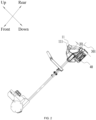
FIG. 1 is a perspective view of a snow shovel according to an example; -
FIG. 2 is a side view of the snow shovel inFIG. 1 ; -
FIG. 3 is another side view of the snow shovel inFIG. 1 with one side plate removed when a connecting rod forms an angle of 45 degrees with the ground; -
FIG. 4 is a side view of the snow shovel inFIG. 1 when a connecting rod forms an angle of 45 degrees with the ground; -
FIG. 5 is a side view of the snow shovel inFIG. 1 placed on the ground; -
FIG. 6 is a side view of the snow shovel inFIG. 1 with a second handle removed; -
FIG. 7 is a side view of the snow shovel inFIG. 1 with a second handle removed and a battery pack folded; -
FIG. 8 is a perspective view of the snow shovel inFIG. 1 with a second handle removed and a battery pack folded; -
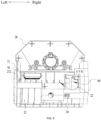
FIG. 9 is a top view of a working head of the snow shovel inFIG. 1 with a housing removed; -
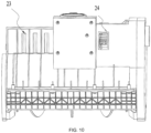
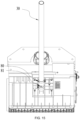
FIG. 10 is a rear view of a working head of the snow shovel inFIG. 1 ; -
FIG. 11 is another top view of a working head of the snow shovel inFIG. 1 with a housing removed; -
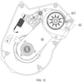
FIG. 12 is a side view of an electric motor of the snow shovel inFIG. 1 ; -
FIG. 13 is a perspective view of part of the snow shovel inFIG. 1 ; -
FIG. 14 is a rear sectional view of a working head of the snow shovel inFIG. 1 ; -
FIG. 15 is a perspective view showing the connection between a working head and a connecting rod of the snow shovel inFIG. 1 ; -
FIG. 16 is a rear sectional view of a connecting rod of the snow shovel inFIG. 1 ; -
FIG. 17 is a side view showing the connection between an operation portion and a connecting rod of the snow shovel inFIG. 1 ; -
FIG. 18 is a side view of the inside of a working head of the snow shovel inFIG. 1 ; -
FIG. 19 is a side view of the standing snow shovel inFIG. 1 ; and -
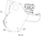
FIG. 20 is a side view of a standing working head of the snow shovel inFIG. 1 . - Before any examples of this application are explained in detail, it is to be understood that this application is not limited to its application to the structural details and the arrangement of components set forth in the following description or illustrated in the above drawings.
- In this application, the terms "comprising", "including", "having" or any other variation thereof are intended to cover an inclusive inclusion such that a process, method, article or device comprising a series of elements includes not only those series of elements, but also other elements not expressly listed, or elements inherent in the process, method, article, or device. Without further limitations, an element defined by the phrase "comprising a ..." does not preclude the presence of additional identical elements in the process, method, article, or device comprising that element.
- In this application, the term "and/or" is a kind of association relationship describing the relationship between associated objects, which means that there can be three kinds of relationships. For example, A and/or B can indicate that A exists alone, A and B exist simultaneously, and B exists alone. In addition, the character "/" in this application generally indicates that the contextual associated objects belong to an "and/or" relationship.
- In this application, the terms "connection", "combination", "coupling" and "installation" may be direct connection, combination, coupling or installation, and may also be indirect connection, combination, coupling or installation. Among them, for example, direct connection means that two members or assemblies are connected together without intermediaries, and indirect connection means that two members or assemblies are respectively connected with at least one intermediate members and the two members or assemblies are connected by the at least one intermediate members. In addition, "connection" and "coupling" are not limited to physical or mechanical connections or couplings, and may include electrical connections or couplings.
- In this application, it is to be understood by those skilled in the art that a relative term (such as "about", "approximately", and "substantially") used in conjunction with quantity or condition includes a stated value and has a meaning dictated by the context. For example, the relative term includes at least a degree of error associated with the measurement of a particular value, a tolerance caused by manufacturing, assembly, and use associated with the particular value, and the like. Such relative term should also be considered as disclosing the range defined by the absolute values of the two endpoints. The relative term may refer to plus or minus of a certain percentage (such as 1%, 5%, 10%, or more) of an indicated value. A value that did not use the relative term should also be disclosed as a particular value with a tolerance. In addition, "substantially" when expressing a relative angular position relationship (for example, substantially parallel, substantially perpendicular), may refer to adding or subtracting a certain degree (such as 1 degree, 5 degrees, 10 degrees or more) to the indicated angle.
- In this application, those skilled in the art will understand that a function performed by an assembly may be performed by one assembly, multiple assemblies, one member, or multiple members. Likewise, a function performed by a member may be performed by one member, an assembly, or a combination of members.
- In this application, the terms "up", "down", "left", "right", "front", and "rear" " and other directional words are described based on the orientation or positional relationship shown in the drawings, and should not be understood as limitations to the examples of this application. In addition, in this context, it also needs to be understood that when it is mentioned that an element is connected "above" or "under" another element, it can not only be directly connected "above" or "under" the other element, but can also be indirectly connected "above" or "under" the other element through an intermediate element. It should also be understood that orientation words such as upper side, lower side, left side, right side, front side, and rear side do not only represent perfect orientations, but can also be understood as lateral orientations. For example, lower side may include directly below, bottom left, bottom right, front bottom, and rear bottom.
-
FIG. 1 illustrates a power tool. The power tool may specifically be a pole power tool, for example, asnow shovel 100, a string trimmer, a pruner, pruning shears, or a wall grinder. As an optional example, thesnow shovel 100 is described below as an example. -
FIG. 1 illustrates asnow shovel 100 for a user to remove snow. Thesnow shovel 100 includes anoperation portion 10, a workinghead 20, a connectingrod 30, and abattery pack 40. Theoperation portion 10 includes afirst handle 11. Thefirst handle 11 is used as a main handle for the user to grip. The workinghead 20 is driven to work, for example, to remove snow. The connectingrod 30 connects thefirst handle 11 to the workinghead 20. Theoperation portion 10 further includes a batterypack mounting portion 12 on which thebattery pack 40 is mounted. Thisbattery pack 40 is configured to power thesnow shovel 100. To facilitate the description of technical solutions, a front side, a rear side, a left side, a right side, an upper side, and a lower side are defined as shown inFIG. 1 . The front side, the rear side, the left side, the right side, the upper side, and the lower side are defined based on the connectingrod 30. The connectingrod 30 may be made of aluminum, thereby reducing the overall weight of thesnow shovel 100 and making thesnow shovel 100 convenient for the user to use. - In the example of the present application, as shown in
FIG. 1 , thefirst handle 11 is disposed at the rear end of the connectingrod 30. Thefirst handle 11 and thebattery pack 40 are disposed vertically along a direction perpendicular to theaxis 301 of the connectingrod 30. That is, along the direction perpendicular to theaxis 301 of the connectingrod 30, thefirst handle 11 and thebattery pack 40 have a vertical disposing relationship. Thefirst handle 11 is disposed on the upper side of thebattery pack 40, or thebattery pack 40 is disposed on the upper side of thefirst handle 11. As shown inFIG. 1 , in the example of the present application, specifically, thefirst handle 11 is disposed on the upper side of thebattery pack 40, and thefirst handle 11 and thebattery pack 40 are disposed on two sides of the connectingrod 30 respectively to be connected to the connectingrod 30. As shown inFIG. 2 , to facilitate the user's operation, the center of a grip of thefirst handle 11 is disposed on the upper side of theaxis 301 of the connectingrod 30, and thebattery pack 40 is disposed on the lower side of theaxis 301 of the connectingrod 30. As shown inFIG. 1 , theoperation portion 10 further includes aspeed adjustment assembly 13 configured to adjust a working speed of thesnow shovel 100. For example, thesnow shovel 100 may have two working speeds: a low speed and a high speed. Thespeed adjustment assembly 13 is operated so that the working speed of thesnow shovel 100 is switched to the low speed or the high speed. In addition, thesnow shovel 100 may have multiple working speeds such as a third speed and a fourth speed. The specific number of speeds of thesnow shovel 100 is not limited in the present application. As shown inFIG. 1 , theoperation portion 10 further includes aswitch assembly 14 configured to control the start or stop of thesnow shovel 100. Both thespeed adjustment assembly 13 and theswitch assembly 14 are disposed on theoperation portion 10 so that it is convenient for the user to control the start and stop of thesnow shovel 100 while gripping thefirst handle 11 and adjust the working speed of thesnow shovel 100 at any time. In addition, as shown inFIG. 2 , a D-shaped space is formed at the position in theoperation portion 10 for the user to grip and is in accord with the shape of the hand of the user gripping thefirst handle 11. - As shown in
FIG. 3 , when the user uses thesnow shovel 100 and the included angle between the axis of the connectingrod 30 and a walking direction of the power tool is 45 degrees, an extension direction of thefirst handle 11 forms a first included angle A with the walking direction of the power tool. The walking direction is the direction the workinghead 20 moves towards when theoperation portion 10 is pushed by a user. The extension direction of thefirst handle 11 refers to the centerline of thehandle 11. The first included angle A is greater than or equal to 30 degrees and less than or equal to 90 degrees. Optionally, the first included angle A is 35 degrees. Optionally, the first included angle A is 45 degrees. Optionally, the first included angle A is 60 degrees. As shown inFIG. 3 , thefirst handle 11 forms a second included angle B with the connectingrod 30. In other words, the second included angle B is between a lower edge of thefirst handle 11 and theaxis 301 of the connectingrod 30. The second included angle B is greater than or equal to 45 degrees and less than or equal to 90 degrees. Optionally, the second included angle B is 50 degrees. Optionally, the second included angle B is 60 degrees. Optionally, the second included angle B is 75 degrees. As shown inFIG. 2 , thefirst handle 11 further includes agrip trigger 111. Thegrip trigger 111 is specifically gripped by the user when thesnow shovel 100 is used. In an up and down direction, the height difference H1 between the central position of thegrip trigger 111 and theaxis 301 of the connectingrod 30 is less than or equal to 200 mm. In addition, the central position of thegrip trigger 111 may be disposed below theaxis 301 of the connectingrod 30. In this case, the height difference H1 between the central position of thegrip trigger 111 and theaxis 301 of the connectingrod 30 is less than or equal to 50 mm. That is, the central position of thegrip trigger 111 may be below theaxis 301 of the connectingrod 30, thegrip trigger 111 is at least partially disposed below theaxis 301 of the connectingrod 30, and the range of the central position of thegrip trigger 111 below theaxis 301 of the connectingrod 30 does not exceed 50 mm. Alternatively, the central position of thegrip trigger 111 may be parallel to theaxis 301 of the connectingrod 30 or may be disposed above theaxis 301 of the connectingrod 30, and the range of the central position of thegrip trigger 111 above theaxis 301 of the connectingrod 30 does not exceed 200 mm. That is, thegrip trigger 111 is at least partially disposed above theaxis 301 of the connectingrod 30 and is parallel to theaxis 301 of the connectingrod 30. The included angle between thefirst handle 11 and the direction in which the power tool is pushed by the user, the included angle between thefirst handle 11 and the connectingrod 30, and the height difference H1 between theaxis 301 of the connectingrod 30 and thegrip trigger 111 which is specifically gripped by the user when using thesnow shovel 100 are configured, which each allow the user to push thesnow shovel 100 with less effort. Thus, it is more convenient for the user to push and use thesnow shovel 100. - In some examples, a
second handle 50 is further disposed on thesnow shovel 100 and is used as an auxiliary handle. Thesecond handle 50 is disposed between thefirst handle 11 and the workinghead 20 and disposed on the connectingrod 30. To facilitate the user's operation, like thefirst handle 11, thesecond handle 50 is also disposed on the upper side of the connectingrod 30. When using thesnow shovel 100, the user can grip both thefirst handle 11 and thesecond handle 50 simultaneously. As shown inFIG. 4 , when the included angle between thesnow shovel 100 and the ground is 45 degrees, the height difference H2 between the central position of thefirst handle 11 and the central position of thesecond handle 50 is less than or equal to 200 mm. That is, in a direction perpendicular to the ground, the range of the central position of thesecond handle 50 below the central position of thefirst handle 11 is less than or equal to 200 mm. Thus, when the user uses thesnow shovel 100, it is convenient for the user to grip both thefirst handle 11 and thesecond handle 50 simultaneously. - In some examples, lighting devices are mounted on the
first handle 11 and/or thesecond handle 50. Thus, when thesnow shovel 100 is used at night or in the dark, the lighting devices can assist the user in clearly seeing theoperation portion 10 for operation and assist the user in clearly seeing a road surface so that it is convenient for the user to use thesnow shovel 100. A respective one of the lighting devices may be disposed at any position on thefirst handle 11 or thesecond handle 50. The positions of the lighting devices are not limited in the present application. Optionally, the lighting devices may be powered by thebattery pack 40. Optionally, the lighting devices may be lighting devices that can store electricity. After being charged through an external power supply, the lighting devices are mounted on thefirst handle 11 and/or thesecond handle 50. Optionally, the lighting devices may be powered in other manners. The manner in which the lighting devices are powered is not limited in the present application. - In some examples, the
battery pack 40 is detachably connected to the connectingrod 30. Thebattery pack 40 is mounted to the connectingrod 30 along a direction parallel to the connectingrod 30. That is, thebattery pack 40 is mounted on the batterypack mounting portion 12 of theoperation portion 10 along the direction parallel to the connectingrod 30 and disposed on the lower side of the connectingrod 30. Thebattery pack 40 is parallel to the connectingrod 30. As shown inFIG. 4 , thebattery pack 40 has afirst length 41 parallel to the connectingrod 30 and asecond length 42 perpendicular to the connectingrod 30. Thefirst length 41 is greater than thesecond length 42. That is, a relatively small surface of thebattery pack 40 is mounted to the batterypack mounting portion 12, and a relatively large surface of thebattery pack 40 is parallel to the connectingrod 30. Since the relatively large surface of thebattery pack 40 is parallel to the connectingrod 30 and thebattery pack 40 is in direct contact with the connectingrod 30, the center of gravity of thebattery pack 40 is higher than the central position of the connectingrod 30. Thus, the gravity of thebattery pack 40 can be shared by the connectingrod 30. Thus, when the user pushes thesnow shovel 100, at least part of the weight of thebattery pack 40 is distributed on the connectingrod 30. That is, the weight of thebattery pack 40 can be distributed along the connectingrod 30 so that the force exerted on the user's hands is reduced during the use of thesnow shovel 100. - As shown in
FIG. 5 , when thesnow shovel 100 is placed on the ground with the workinghead 20 and thebattery pack 40 both on the ground, thebattery pack 40 forms a third included angle C with the ground. The included angle C is between a lower edge of thebattery pack 40 and the ground. The third included angle C is less than or equal to 30 degrees. Since the included angle between thebattery pack 40 and the ground is relatively small, a relatively large area on thebattery pack 40 is in contact with the ground. Thus, when the user stops using thesnow shovel 100 and releases it, thebattery pack 40 is less likely to impact the ground and be damaged. - In some examples, as shown in
FIG. 6 , the connectingrod 30 includes a first connectingrod 31 and a second connectingrod 32. The first connectingrod 31 and the second connectingrod 32 are connected to each other through a connectingassembly 33 to form the connectingrod 30. The first connectingrod 31 is connected to the workinghead 20, and the second connectingrod 32 is connected to theoperation portion 10. The connectingassembly 33 is foldable. Thus, the connectingassembly 33 is folded so that the connectingrod 30 is folded, causing thesnow shovel 100 to be in a folded state. Optionally, the snow shovel shown inFIG. 6 may be thesnow shovel 100 shown inFIG. 1 with thesecond handle 20 removed. Optionally, the snow shovel shown inFIG. 6 may be a snow shovel in another example. - Optionally, both the first connecting
rod 31 and the second connectingrod 32 may be linear connecting rods. That is, the connectingrod 30 is a linear connecting rod. Then, theaxis 301 of the connectingrod 30 is a linear axis. Optionally, the connectingrod 30 may be constituted by a curved connecting rod and a linear connecting rod, and theaxis 301 of the connectingrod 30 may include a curved axis and a linear axis. The portion of the connectingrod 30 connected to theoperation portion 10 is the linear connecting rod while the portion of the connectingrod 30 connected to the workinghead 20 is the curved connecting rod. That is, the second connectingrod 32 may be the linear connecting rod, and the first connectingrod 31 may be the curved connecting rod. In the present application, theaxis 301 of the connectingrod 30 may be linear or may be partially linear. The linear connectingrod 30 is used as an example for description in the present application. - As shown in
FIG. 7 , when thesnow shovel 100 is in the folded state, theuppermost end 201 of the workinghead 20 away from theaxis 301 of the connectingrod 30 is connected to anend 311 of the first connectingrod 31 away from the workinghead 20 to form a firststraight line 34. That is, theuppermost end 201 of the workinghead 20 in the direction perpendicular to theaxis 301 of the connectingrod 30 is connected to theend 311 of the first connectingrod 31 that is not connected to the workinghead 20 such that the firststraight line 34 is formed. As shown inFIG. 7 , the center of thefirst handle 11 is located between the firststraight line 34 and the first connectingrod 31. The firststraight line 34, the first connectingrod 31, and the workinghead 20 form a triangular region M. The center of thefirst handle 11 is located within this triangular region M. To ensure that the center of thefirst handle 11 is located within the triangular region M, that is, thefirst handle 11 is not located above the workinghead 20 after being folded, As shown inFIG. 8 , a preset projection of the second connectingrod 32 and theoperation portion 10 is formed on a plane N parallel to theaxis 301 of the connectingrod 30 and perpendicular to the workinghead 20. Additionally, the length of the first connectingrod 31 is greater than or equal to the length of this preset projection. - As shown in
FIG. 7 , when thesnow shovel 100 is in the folded state, the distance H3 between the center of thefirst handle 11 and theaxis 301 of the first connectingrod 31 is less than or equal to 270 mm. Optionally, thefirst handle 11 may abut against the first connectingrod 31. Thefirst handle 11 is in contact with the first connectingrod 31. In this case, the distance between the center of thefirst handle 11 and theaxis 301 of the first connectingrod 31 is minimized. Optionally, thefirst handle 11 may not be in contact with the first connectingrod 31 and thefirst handle 11 is located above the first connectingrod 31 as long as the center of thefirst handle 11 only needs to be located within the triangular region M. Optionally, when the distance between the center of thefirst handle 11 and theaxis 301 of the first connectingrod 31 is 105 mm, thefirst handle 11 is the closest to the first connectingrod 31. That is, in this case, thefirst handle 11 is in contact with the first connectingrod 31. Optionally, when the distance between the center of thefirst handle 11 and theaxis 301 of the first connectingrod 31 is 270 mm, thefirst handle 11 is the farthest from the first connectingrod 31. That is, the center of thefirst handle 11 is at the edge of the triangular region M and on the firststraight line 34. - As shown in
FIG. 8 , when thesnow shovel 100 is in the folded state, the second connectingrod 32 is located above the first connectingrod 31. That is, the second connectingrod 32 is folded toward the upper side of the connectingrod 30, thereby folding thesnow shovel 100. In this case, as shown inFIG. 7 , the distance H4 between the center of thefirst handle 11 and apreset position 211 on ahousing 21 of the workinghead 20 is less than or equal to 200 mm. The connecting line from thepreset position 211 on thehousing 21 of the workinghead 20 to the center of thefirst handle 11 is parallel to theaxis 301 of the first connectingrod 31. Optionally, thefirst handle 11 may abut against the workinghead 20. Thefirst handle 11 is in contact with thehousing 21 of the workinghead 20. Optionally, thefirst handle 11 may not be in contact with thehousing 21 of the workinghead 20. Thesnow shovel 100 is folded so that thesnow shovel 100 can have a relatively small volume. Thus, it is convenient to store and carry thesnow shovel 100. In addition, thesnow shovel 100 is folded toward the upper side of the connectingrod 30 in this example, and thus, the foldedsnow shovel 100 has a smaller volume than that of thesnow shovel 100 folded in other manners. Furthermore, to minimize the volume of the foldedsnow shovel 100, thefirst handle 11 may be caused to abut against the first connectingrod 31. - In some examples, when the
snow shovel 100 is in the folded state, the height of theoperation portion 10 is less than or equal to the height of the workinghead 20 along the up and down direction perpendicular to theaxis 301 of the first connectingrod 31. Thus, the volume of the foldedsnow shovel 100 is further reduced. - In some examples, as shown in
FIG. 6 , the connectingassembly 33 includes a first connectingassembly 331 and a second connectingassembly 332. The first connectingassembly 331 is sleeved on the first connectingrod 31. The second connectingassembly 332 is sleeved on the second connectingrod 32. The first connectingassembly 331 and the second connectingassembly 332 are connected to each other through at least two sets of fixingassemblies 35 to form the connectingassembly 33. The two sets of fixingassemblies 35 include a first set of fixing assemblies 351 and a second set of fixingassemblies 352. The first set of fixing assemblies 351 is disposed on the first connectingrod 31. The second set of fixingassemblies 352 is disposed under the first connectingrod 31. The first set of fixing assemblies 351 is rotatable. Thus, after the second set of fixingassemblies 352 is removed, the second connectingrod 32 or the first connectingrod 31 is rotated based on the first set of fixing assemblies 351 to fold the connectingrod 30. The second connectingrod 32 may be rotated upward in a counterclockwise direction or the first connectingrod 31 may be rotated upward in a clockwise direction so that the connectingrod 30 is folded. Optionally, three sets of fixingassemblies 35 may be provided. Two of the three sets of fixingassemblies 35 are fixed under the first connectingrod 31. One of the three sets of fixingassemblies 35 is fixed on the first connectingrod 31. The set of fixingassemblies 35 fixed on the first connectingrod 31 is rotatable. Optionally, four sets of fixingassemblies 35 may be provided. Three of the four sets of fixingassemblies 35 are fixed under the first connectingrod 31. One of the four sets of fixingassemblies 35 is fixed on the first connectingrod 31. The set of fixingassemblies 35 fixed on the first connectingrod 31 is rotatable. In addition, other numbers of multiple sets of fixingassemblies 35 may be provided, which is not limited in the present application. The set of fixing assemblies fixed on the first connectingrod 31 is always one set of rotatable fixing assemblies. - In some examples, a connecting wire between the working
head 20 and theoperation portion 10 is disposed within the connectingrod 31. The connecting wire passes through the connectingrod 31 to connect the workinghead 20 to theoperation portion 10. Thus, thesnow shovel 100 is folded so that the connecting wire is prevented from being pulled and damaged during the disassembly of thesnow shovel 100. - In some examples, when the
snow shovel 100 is folded, thebattery pack 40 and thesecond handle 50 may be removed so that the foldedsnow shovel 100 has a smaller volume. As shown inFIG. 8 , when thesnow shovel 100 is in the folded state, two sides of thefirst handle 11 can form accommodation spaces with the workinghead 20 because the volume of the workinghead 20 is larger than that of theoperation portion 10. Thebattery pack 40 and thesecond handle 50 may be placed in the accommodation spaces on the two sides, respectively. Thus, when thesnow shovel 100 is stored, the overall volume of thesnow shovel 100 to be stored is smaller, and all components of thesnow shovel 100 can be stored. - As shown in
FIG. 9 , the workinghead 20 includes ahousing 21 and anauger 22. Thehousing 21 is formed with an accommodation space 212. Thesnow shovel 100 includes anelectric motor 60 and acircuit board 70. Both theelectric motor 60 and thecircuit board 70 are disposed in the accommodation space 212. Theelectric motor 60 is configured to drive theauger 22. Thecircuit board 70 is configured to control the running of theelectric motor 60. As shown inFIG. 10 , thesnow shovel 100 also includes a heatdissipation airflow inlet 23 and a heatdissipation airflow outlet 24. The heatdissipation airflow inlet 23 causes the inside and outside of the accommodation space 212 to communicate with each other. The heatdissipation airflow outlet 24 also causes the inside and outside of the accommodation space 212 to communicate with each other. The shapes or structures of the heatdissipation airflow inlet 23 and the heatdissipation airflow outlet 24 are not limited in the present application. Any shape or structure that allows an airflow to circulate is acceptable. Thus, when thesnow shovel 100 is in operation, the user pushes thesnow shovel 100 back and forth. Therefore, a heat dissipation airflow can enter through the heatdissipation airflow inlet 23, flow through thecircuit board 70 and theelectric motor 60, and exit through the heatdissipation airflow outlet 24. Thus, thecircuit board 70 and theelectric motor 60 are cooled down through the heat dissipation airflow during the use of thesnow shovel 100, thereby solving the problem that thecircuit board 70 and theelectric motor 60 are at excessively high temperatures when in operation for a long period of time. Therefore, compared with theprevious snow shovel 100 with thecircuit board 70 and theelectric motor 60 disposed in theoperation portion 10, the present application causes thecircuit board 70 and theelectric motor 60 to be disposed in the workinghead 20. Thus, thecircuit board 70 and theelectric motor 60 can be prevented from an overtemperature, thereby prolonging their service lives and reducing the costs of long-term use of thesnow shovel 100. Moreover, thecircuit board 70 and theelectric motor 60 are disposed in the workinghead 20, thereby avoiding an excessive weight of theoperation portion 10. The weight of theoperation portion 10 is reduced, which allows the user to push thesnow shovel 100 with less effort. Optionally, the working head of the snow shovel shown inFIG. 9 may be the workinghead 20 of thesnow shovel 100 shown inFIG. 1 or may be the working head of a snow shovel in another example. - In some examples, as shown in
FIG. 9 , thecircuit board 70 is disposed on a first side of the accommodation space 212, and the heatdissipation airflow inlet 23 corresponds to thecircuit board 70 and is also provided on the first side of the accommodation space 212. Theelectric motor 60 is disposed on the second side of the accommodation space 212, and the heatdissipation airflow outlet 24 corresponds to theelectric motor 60 and is also provided on the second side of the accommodation space 212. When the left side of the accommodation space 212 is defined as the first side, the second side is the right side of the accommodation space 212. When the right side of the accommodation space 212 is defined as the first side, the second side is the left side of the accommodation space 212. The present application does not define the first side or the second side as a specific side of the accommodation space 212 as long as the heatdissipation airflow inlet 23 and thecircuit board 70 are on the same side and the heatdissipation airflow outlet 24 and theelectric motor 60 are on the same side. - In some examples, as shown in
FIG. 11 , to facilitate better heat dissipation for thecircuit board 70, aheat sink 71 is disposed on thecircuit board 70. Optionally, the heat dissipation airflow enters through the heatdissipation airflow inlet 23, passes through theheat sink 71 on thecircuit board 70, and then flows toward theelectric motor 60. Optionally, as shown inFIG. 12 , theelectric motor 60 is disposed in aheat dissipation assembly 61 for an electric motor. Theheat dissipation assembly 61 for the electric motor is an independent volute. Theheat dissipation assembly 61 for the electric motor may have a smooth Archimedean spiral-like shape. Thus, when flowing from thecircuit board 70 to theelectric motor 60, the heat dissipation airflow passes through theheat dissipation assembly 61 for the electric motor to flow through theelectric motor 60 and exits through an outlet of theheat dissipation assembly 61 for the electric motor. The outlet of theheat dissipation assembly 61 for the electric motor is connected to the heatdissipation airflow outlet 24 so that the heat dissipation airflow can directly exit from thesnow shovel 100. Optionally, afan 611 is disposed in theheat dissipation assembly 61 for the electric motor. Thefan 611 is connected to theelectric motor 60. Theelectric motor 60 runs to drive thefan 611 to rotate. Thus, when theelectric motor 60 runs, the rotatingfan 611 can drive the heat dissipation airflow to flow from thecircuit board 70 to theheat dissipation assembly 61 for the electric motor and exit from theheat dissipation assembly 61 for the electric motor. In addition, the rotatingfan 611 can also drive the heat dissipation airflow to enter from the heatdissipation airflow inlet 23 and flow through thecircuit board 70. Theheat dissipation assembly 61 for the electric motor is configured to have a smooth Archimedean spiral-like shape so that the heat dissipation airflow can fully circulate around theelectric motor 60 before exiting. Thus, the heat dissipation effect of theelectric motor 60 is enhanced, thereby improving the efficiency of theelectric motor 60. The service life of theelectric motor 60 is further prolonged, and the costs of the long-term use of thesnow shovel 100 are further reduced. - As shown in
FIG. 13 , both the heatdissipation airflow inlet 23 and the heatdissipation airflow outlet 24 face downward. Thus, when the user uses thesnow shovel 100, the airflow generated by the user pushing thesnow shovel 100 facilitates the entrance and exit of the heat dissipation airflow. Theauger 22 is also disposed in the accommodation space 212. Optionally, as shown inFIG. 14 , both the heatdissipation airflow inlet 23 and the heatdissipation airflow outlet 24 are provided above theauger 22. Optionally, the heatdissipation airflow inlet 23 and the heatdissipation airflow outlet 24 may be provided in other directions of theauger 22, which is not limited in the present application. With respect to the direction of the snow shovel 100 (that is, along the direction of the connecting rod 30), both the heatdissipation airflow inlet 23 and the heatdissipation airflow outlet 24 are provided behind theauger 22. - In some examples, since the
circuit board 70 and theelectric motor 60 are both disposed in the workinghead 20, the connectingrod 30 is fixedly connectable to both the workinghead 20 and theoperation portion 10. As shown inFIGS. 15 and16 , the connectingrod 30 may be fixed to the workinghead 20 through twohoops 80. In addition, the connectingrod 30 may be fixed to the workinghead 20 through other numbers ofhoops 80. The number ofhoops 80 is not limited in the present application. To avoid the case where the connectingrod 30 moves up and down after being fixed to the workinghead 20, that is, the connectingrod 30 moves back and forth along thesnow shovel 100 and to avoid the rotation of the connectingrod 30, at least one limit hole 81 may be provided on the connectingrod 30, and a limithole mating assembly 82 may be disposed on the workinghead 20 to mate with the limit hole 81. Similarly, as shown inFIG. 17 , the connectingrod 30 may also be fixed to theoperation portion 10 through twohoops 80. In addition, the connectingrod 30 may also be fixed to theoperation portion 10 through other numbers ofhoops 80. The number ofhoops 80 is not limited in the present application. Similarly, a limit hole 81 and a limithole mating assembly 82 may mate with each other such that the connectingrod 30 is prevented from rotating or moving relative to theoperation portion 10. The details are not repeated here. The connectingrod 30 is fixed to the workinghead 20 and theoperation portion 10 throughloops 80 so that the connectingrod 30 generates no noise during the use of thesnow shovel 100. Optionally, the manner in which the working head and the connecting rod of the snow shovel are connected to each other shown inFIGS. 15 and16 may be the manner in which the workinghead 20 and the connectingrod 30 of thesnow shovel 100 are connected to each other shown inFIG. 1 or may be the manner in which the working head and the connecting rod of a snow shovel are connected to each other in another example. - In some examples, to enable the
electric motor 60 to drive theauger 22 to work, afirst pulley 91 is connected to theelectric motor 60, asecond pulley 92 is connected to the rotation shaft of theauger 22, and thefirst pulley 91 and thesecond pulley 92 are connected to each other throughmultiple belts 93. Thefirst pulley 91 is smaller than thesecond pulley 92. A height difference may occur between thefirst pulley 91 and thesecond pulley 92 after the long-term use of thesnow shovel 100, causing thesnow shovel 100 to be incapable of working normally. To avoid the case described above, as shown inFIG. 18 , a fixingplate 94 is disposed in the workinghead 20. Thefirst pulley 91 and thesecond pulley 92 are mounted at two ends of the fixingplate 94, respectively. Thus, thefirst pulley 91 and thesecond pulley 92 are always maintained at the same height through the fixingplate 94. Thus, the service lives of the two pulleys are prolonged, and it is ensured that thesnow shovel 100 works normally. - In some examples, as shown in
FIGS. 19 and20 , the workinghead 20 further includes afirst side plate 25 and asecond side plate 26. Thefirst side plate 25 and thesecond side plate 26 are the left and right side plates of the workinghead 20, respectively. Thefirst side plate 25 includes afirst contact point 251 and asecond contact point 252. Thesecond side plate 26 includes athird contact point 261 and afourth contact point 262. Thesnow shovel 100 is supported by thefirst contact point 251, thesecond contact point 252, thethird contact point 261, and thefourth contact point 262 to stand. When thesnow shovel 100 stands, the center of gravity of theoperation portion 10 and the center of gravity of thebattery pack 40 are both within a center ofgravity range 27 defined by thefirst contact point 251 and thesecond contact point 252. The range between a first center ofgravity plane 271 and a second center ofgravity plane 272 is defined as the center ofgravity range 27. The first center ofgravity plane 271 is a plane that is perpendicular to the connecting line from thefirst contact point 251 to thesecond contact point 252 and passes through thefirst contact point 251. The second center ofgravity plane 272 is a plane that is perpendicular to the connecting line from thefirst contact point 251 to thesecond contact point 252 and passes through thesecond contact point 252. Thus, since the center of gravity of theoperation portion 10 and the center of gravity of thebattery pack 40 are both within the center ofgravity range 27, thesnow shovel 100 can stand stably. - In some examples, the connecting line from the
first contact point 251 to thethird contact point 261 is parallel to the connecting line from thesecond contact point 252 to thefourth contact point 262. Thus, the first center ofgravity plane 271 may be a plane that is perpendicular to the connecting line from thefirst contact point 251 to thesecond contact point 252 and passes through thethird contact point 261, and the second center ofgravity plane 272 may be a plane that is perpendicular to the connecting line from thefirst contact point 251 to thesecond contact point 252 and passes through thefourth contact point 262. Optionally, the standing manner of the snow shovel shown inFIG. 19 may be the standing manner of thesnow shovel 100 shown inFIG. 1 or may be the standing manner of a snow shovel in another example. - The basic principles, main features, and advantages of this application are shown and described above. It is to be understood by those skilled in the art that the aforementioned examples do not limit the present application in any form, and all technical solutions obtained through equivalent substitutions or equivalent transformations fall within the scope of the present application.
Claims (15)
- A power tool, comprising:an operation portion comprising a first handle for a user to grip;a working head drivable to work;a connecting rod connecting the first handle to the working head; anda battery pack configured to power the power tool;wherein the first handle is disposed at a rear end of the connecting rod, and the first handle and the battery pack are disposed vertically along a direction perpendicular to an axis of the connecting rod; and when an included angle between the axis of the connecting rod and a walking direction of the power tool is 45 degrees, an extension direction of the first handle forms a first included angle with the walking direction of the power tool, wherein the first included angle is greater than or equal to 30 degrees and less than or equal to 90 degrees.
- The power tool according to claim 1, wherein a lower edge of the first handle forms a second included angle with the axis of the connecting rod, wherein the second included angle is greater than or equal to 45 degrees and less than or equal to 90 degrees.
- The power tool according to claim 1, wherein the first handle further comprises a grip trigger, and a height difference between a central position of the grip trigger and the axis of the connecting rod is less than or equal to 200 mm.
- The power tool according to claim 1, wherein a center of a grip of the first handle is disposed on an upper side of the axis of the connecting rod, and the battery pack is disposed on a lower side of the axis of the connecting rod.
- The power tool according to claim 1, wherein the battery pack is detachably connected to the connecting rod and is mounted to the connecting rod along a direction parallel to the connecting rod.
- The power tool according to claim 5, wherein the battery pack has a first length parallel to the connecting rod and a second length perpendicular to the connecting rod, wherein the first length is greater than the second length.
- The power tool according to claim 1, further comprising a second handle disposed on an upper side of the connecting rod.
- The power tool according to claim 7, wherein the second handle is disposed between the first handle and the working head, and when the included angle between the axis of the connecting rod and the walking direction of the power tool is 45 degrees, a height difference between a central position of the second handle and a central position of the first handle is less than or equal to 200 mm.
- The power tool according to claim 1, wherein the operation portion further comprises a speed adjustment assembly configured to adjust a working speed of the power tool.
- The power tool according to claim 1, wherein when the power tool is placed on the ground with the working head and the battery pack both touching the ground, the battery pack forms a third included angle with the ground, wherein the third included angle is less than or equal to 30 degrees.
- The power tool according to claim 1, wherein the connecting rod comprises a first connecting rod connected to the working head and a second connecting rod connected to the operation portion, the first connecting rod and the second connecting rod are connected to each other through a connecting assembly, the connecting assembly is a foldable assembly, and the connecting assembly is folded so that the connecting rod is folded, causing the power tool to be in a folded state.
- The power tool according to claim 11, wherein when the power tool is in the folded state, an uppermost end of the working head away from the axis of the connecting rod is connected to an end of the first connecting rod away from the working head to form a first straight line, and a center of the first handle is located between the first straight line and the first connecting rod.
- The power tool according to claim 11, wherein when the power tool is in the folded state, the second connecting rod is located above the first connecting rod.
- The power tool according to claim 12, wherein when the power tool is in the folded state, the first straight line, the first connecting rod, and the working head form a triangular region.
- The power tool according to claim 11, wherein when the power tool is in the folded state, a height of the operation portion is less than or equal to a height of the working head along an up and down direction perpendicular to the axis of the first connecting rod.
Applications Claiming Priority (3)
| Application Number | Priority Date | Filing Date | Title |
|---|---|---|---|
| CN202323602873.3U CN221480679U (en) | 2023-12-27 | 2023-12-27 | electrical tools |
| CN202311838640.5A CN120244879A (en) | 2023-12-27 | 2023-12-27 | Power Tools |
| CN202323596144.1U CN222594715U (en) | 2023-12-27 | 2023-12-27 | Snow shovel |
Publications (2)
| Publication Number | Publication Date |
|---|---|
| EP4579042A2 true EP4579042A2 (en) | 2025-07-02 |
| EP4579042A3 EP4579042A3 (en) | 2025-08-27 |
Family
ID=93455544
Family Applications (1)
| Application Number | Title | Priority Date | Filing Date |
|---|---|---|---|
| EP24211322.3A Pending EP4579042A3 (en) | 2023-12-27 | 2024-11-07 | Power tool |
Country Status (2)
| Country | Link |
|---|---|
| US (1) | US20250215652A1 (en) |
| EP (1) | EP4579042A3 (en) |
Family Cites Families (4)
| Publication number | Priority date | Publication date | Assignee | Title |
|---|---|---|---|---|
| US9414540B2 (en) * | 2010-03-24 | 2016-08-16 | Aero-Flex Technologies, Inc. | Oriented trimmer line |
| AT14057U1 (en) * | 2014-01-17 | 2015-03-15 | Sonneck Ges M B H | snowblower |
| DE102015207151A1 (en) * | 2015-04-20 | 2016-10-20 | Robert Bosch Gmbh | Fastener for hand tool |
| US12622350B2 (en) * | 2017-08-07 | 2026-05-12 | Nanjing Chervon Industry Co., Ltd. | Grass trimming head and grass trimmer having the same |
-
2024
- 2024-11-06 US US18/938,536 patent/US20250215652A1/en active Pending
- 2024-11-07 EP EP24211322.3A patent/EP4579042A3/en active Pending
Also Published As
| Publication number | Publication date |
|---|---|
| US20250215652A1 (en) | 2025-07-03 |
| EP4579042A3 (en) | 2025-08-27 |
Similar Documents
| Publication | Publication Date | Title |
|---|---|---|
| US12492521B2 (en) | Snow thrower | |
| US10485166B2 (en) | Power tool | |
| EP3821692B1 (en) | Lawn mower | |
| US20220183241A1 (en) | Garden blower | |
| CN101817106A (en) | Battery-driven portable handheld work apparatus | |
| JP2014148950A (en) | Electric blower | |
| EP3302019B1 (en) | High-efficiency lawn maintenance tool | |
| CN106258180A (en) | Hand-push type mower | |
| CN207269427U (en) | Pruner | |
| US20250215652A1 (en) | Power tool | |
| US20230371449A1 (en) | Garden blower | |
| CN217644222U (en) | Grass cutter | |
| CN117337685A (en) | A hand-push power tool | |
| CN221480679U (en) | electrical tools | |
| CN105673528B (en) | Electric tool | |
| CN222594715U (en) | Snow shovel | |
| CN207505508U (en) | Pruner | |
| CN208707470U (en) | A kind of more operated type electric tools | |
| AU2015101657B4 (en) | An electric tool | |
| CN204327537U (en) | A kind of electric tool | |
| CN117356248A (en) | a lawn mower | |
| CN120244879A (en) | Power Tools | |
| CN207505510U (en) | Pruner | |
| EP4298887A1 (en) | Mower | |
| CN208079802U (en) | A kind of Novel grass cutter |
Legal Events
| Date | Code | Title | Description |
|---|---|---|---|
| PUAI | Public reference made under article 153(3) epc to a published international application that has entered the european phase |
Free format text: ORIGINAL CODE: 0009012 |
|
| STAA | Information on the status of an ep patent application or granted ep patent |
Free format text: STATUS: THE APPLICATION HAS BEEN PUBLISHED |
|
| AK | Designated contracting states |
Kind code of ref document: A2 Designated state(s): AL AT BE BG CH CY CZ DE DK EE ES FI FR GB GR HR HU IE IS IT LI LT LU LV MC ME MK MT NL NO PL PT RO RS SE SI SK SM TR |
|
| PUAL | Search report despatched |
Free format text: ORIGINAL CODE: 0009013 |
|
| AK | Designated contracting states |
Kind code of ref document: A3 Designated state(s): AL AT BE BG CH CY CZ DE DK EE ES FI FR GB GR HR HU IE IS IT LI LT LU LV MC ME MK MT NL NO PL PT RO RS SE SI SK SM TR |
|
| RIC1 | Information provided on ipc code assigned before grant |
Ipc: E01H 5/09 20060101AFI20250723BHEP |
|
| STAA | Information on the status of an ep patent application or granted ep patent |
Free format text: STATUS: REQUEST FOR EXAMINATION WAS MADE |
|
| 17P | Request for examination filed |
Effective date: 20260203 |