EP4579017A1 - Schussfadenliefervorrichtung mit regelbarem durchmesser für webmaschinen mit einer elektromagneteinheit zur steuerung der schussfadenfreigabe - Google Patents
Schussfadenliefervorrichtung mit regelbarem durchmesser für webmaschinen mit einer elektromagneteinheit zur steuerung der schussfadenfreigabe Download PDFInfo
- Publication number
- EP4579017A1 EP4579017A1 EP24218332.5A EP24218332A EP4579017A1 EP 4579017 A1 EP4579017 A1 EP 4579017A1 EP 24218332 A EP24218332 A EP 24218332A EP 4579017 A1 EP4579017 A1 EP 4579017A1
- Authority
- EP
- European Patent Office
- Prior art keywords
- weft feeder
- weft
- electromagnet unit
- drum
- pair
- Prior art date
- Legal status (The legal status is an assumption and is not a legal conclusion. Google has not performed a legal analysis and makes no representation as to the accuracy of the status listed.)
- Pending
Links
Images

Classifications
-
- D—TEXTILES; PAPER
- D03—WEAVING
- D03D—WOVEN FABRICS; METHODS OF WEAVING; LOOMS
- D03D47/00—Looms in which bulk supply of weft does not pass through shed, e.g. shuttleless looms, gripper shuttle looms, dummy shuttle looms
- D03D47/34—Handling the weft between bulk storage and weft-inserting means
- D03D47/36—Measuring and cutting the weft
- D03D47/361—Drum-type weft feeding devices
- D03D47/362—Drum-type weft feeding devices with yarn retaining devices, e.g. stopping pins
- D03D47/363—Construction or control of the yarn retaining devices
-
- D—TEXTILES; PAPER
- D03—WEAVING
- D03D—WOVEN FABRICS; METHODS OF WEAVING; LOOMS
- D03D47/00—Looms in which bulk supply of weft does not pass through shed, e.g. shuttleless looms, gripper shuttle looms, dummy shuttle looms
- D03D47/34—Handling the weft between bulk storage and weft-inserting means
Definitions
- the present invention relates to a new weft feeder for weaving looms, and particularly for air jets looms and water jet looms, which includes, in addition to the normal functions already offered by the currently available weft feeders of the known type, an electromagnet unit controlling the weft thread release, equipped with a quick-release adjustment device to obtain a precise adjustment of its working position.
- weft feeders are weft thread feeding devices, interposed between the loom and the yarn spools, which feeds the loom with the weft thread by continuously accumulating it in successive coils on a cylindrical drum at as constant a speed as possible - in the clockwise or counterclockwise direction depending on the thread features - so as to create a reserve of weft thread which is subsequently extracted from the weft feeder drum in the axial direction, at variable speed, during the operation of insertion in the shed, without thus causing tension peaks in the weft thread, which would undermine both the integrity of the thread itself and the quality of the fabric.
- Weft feeders are devices which have been in current use for many years in the weaving mills. Along their evolution over the years, in addition to the basic functions mentioned above, they have been enhanced with additional control functions which allow to check the weft thread constant presence at certain critical points of the weft feeder, to adjust the amount of weft thread accumulated in the reserve and the distance between the individual coils, to slow down the outgoing weft thread in order to contain the dynamic effects caused by the sudden drawing acceleration, and finally to control the weft thread release in a predetermined length for insertion in the shed formed by the warp threads.
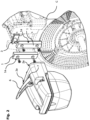
- the weft feeder ( Fig. 1 ) is equipped with an optical unit and an electromagnet unit E (hereinafter also referred to as "ELM unit”) .
- the optical unit includes one or more optical sensors and performs the function of monitoring the weft thread winding on the drum D by a winding group W which is integral with the weft feeder hollow shaft A, by retroactively controlling the weft feeder electric engine which controls the hollow shaft A rotation and therefore the deposition of new coils of weft thread on the drum D, as well as the function of counting the number of coils released from drum D to the weft insertion devices.
- the ELM unit controls the rectilinear movement of a weft thread stop pin P between an advanced position, wherein its free end is inserted into a corresponding seat provided in the drum D, thus preventing the weft thread from being released from the weft feeder drum, and a retracted position which allows instead the weft thread to be released. Thanks to the combined action of the optical unit and the ELM unit the weft thread may thus be drawn from the loom in a predefined number of coils, corresponding to the desired length of weft thread to be inserted in the shed.
- the distance between the ELM unit and the drum D shall be determined with such a precision as to allow the optical unit sensors to correctly detect the passage of the weft thread, and the stop pin P of the ELM unit to sufficiently enter the corresponding seat of the drum D to hold the weft thread coils on the drum D.
- the drum D working diameter may be modified in every single processing, in order to change the length of the weft thread section fed to the loom, and it is then necessary that the position of the whole ELM unit, mounted directly on the weft feeder base body C, is adjusted as quickly and stably as possible, to chase the new position of the drum D and then stably maintain a predetermined optimal working distance from the same.
- the ELM unit slides along a pair of guide means, respectively provided in the weft feeder base body C and in the ELM unit itself, and having a radial direction with respect to the weft feeder drum D.
- the ELM unit is then fixed in a desired position by a pawl which slides within the guide means provided in the base body.
- Said pawl is in fact secured to the ELM unit via the engagement with a screw passing through the same, in the parallel direction to the drum D axis, and may be therefore locked in position by acting on said screw to pull the pawl into abutment against said guide means. In this way, the ELM unit sliding may be stopped at any desired position along said guide means.
- the technical problem addressed by the present invention is therefore to provide a weft feeder with adjustable-diameter drum wherein the ELM unit working position may be fast adjusted and thus the ELM unit may be fixed in such a position with high precision and repeatability.
- a first object of the present invention is to provide an ELM unit equipped with an adjustment and fixing device of its working position, suitable to ensure a constant parallelism of the ELM unit lower plane with the reference sector of the weft feeder drum D, as well as a correct centering of the stop pin P with the corresponding seat provided in the drum D.
- a second object of the present invention is then to provide an ELM unit wherein said adjustment and fixing device may be quickly operated, preferably without the use of tools.
- a third object of the present invention is to provide an ELM unit, the adjustment and fixing device of which maintains a stable and unchanged ELM unit working position even during the adjustment and fixing operation.
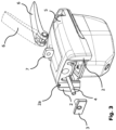
- the ELM unit When the eccentric lever 6 is in the open position, in fact, the ELM unit is free to move along the guides 1, 2 until being positioned at the desired height with respect to the weft feeder drum. Conversely, when the eccentric lever is in the closed position the ELM unit remains perfectly locked in the desired position.
- the ELM unit locking/unlocking device is imparted with a feature of automatic centering of the ELM unit position with respect to said axial plane, and is therefore able to ensure a constant repeatability of the position of the ELM unit with respect to the weft feeder base body C at each subsequent adjustment od said position, while also removing any possible rotary oscillation of the ELM unit about the axis of the locking/unlocking device consisting of the pawl 3 and the tie-rod 4.
- the ELM unit quick-release locking/unlocking device also allows a tie-rod 4 desired preload force to be set during manufacturing, by inserting a suitable elastic means, so that even in the unlocked position the ELM unit is held in position against the guides 1 by an adequate preload force.
- said elastic means is a small block 7, made of rubber or other elastic material, interposed between the eccentric lever 6 and an abutment surface of the body 5, as clearly shown in Figs. 2 and 3 .
- said preload force shall be high enough to prevent the ELM unit from moving under the sole action of its own weight, and said preload force shall be low enough to allow the ELM unit movement along the guides 1, when a suitable force is manually applied thereon in such a direction.
- This solution ensures a greater precision of the position of the ELM unit, both because the ELM unit remains stationary in the adjustment positions set from time to time while the eccentric lever 6 is in the unlocked position, and because, when acting on said eccentric lever 6 to lock the ELM unit, no change in the ELM unit position occurs as a result of the pawl 3 tightening against the guides 1, precisely thanks to the preload force exerted by the small block 7, and therefore the ELM unit adjustment position and locking position are perfectly coincident.
- the pairs of guides with opposite inclined surfaces 1a and 2a allow to maintain the ELM unit lower plane constantly parallel to the reference sector of the weft feeder drum D, and the stop pin P correctly centered on the respective seat formed on the drum D.
Landscapes
- Engineering & Computer Science (AREA)
- Textile Engineering (AREA)
- Looms (AREA)
Applications Claiming Priority (1)
| Application Number | Priority Date | Filing Date | Title |
|---|---|---|---|
| IT102023000028116A IT202300028116A1 (it) | 2023-12-27 | 2023-12-27 | Porgitrama con tamburo a diametro regolabile per telai di tessitura comprendente un gruppo elettromagnete di rilascio del filo di trama munito di un dispositivo rapido di regolazione precisa della sua posizione di lavoro |
Publications (1)
| Publication Number | Publication Date |
|---|---|
| EP4579017A1 true EP4579017A1 (de) | 2025-07-02 |
Family
ID=90363150
Family Applications (1)
| Application Number | Title | Priority Date | Filing Date |
|---|---|---|---|
| EP24218332.5A Pending EP4579017A1 (de) | 2023-12-27 | 2024-12-09 | Schussfadenliefervorrichtung mit regelbarem durchmesser für webmaschinen mit einer elektromagneteinheit zur steuerung der schussfadenfreigabe |
Country Status (4)
| Country | Link |
|---|---|
| EP (1) | EP4579017A1 (de) |
| JP (1) | JP2025104291A (de) |
| CN (1) | CN120211012A (de) |
| IT (1) | IT202300028116A1 (de) |
Citations (4)
| Publication number | Priority date | Publication date | Assignee | Title |
|---|---|---|---|---|
| WO1992003604A1 (de) * | 1990-08-21 | 1992-03-05 | Iro Ab | Verfahren zum steuern einer schussfadenliefer- und -messvorrichtung sowie schussfadenliefer- und -messvorrichtung |
| EP0540864A1 (de) * | 1991-11-06 | 1993-05-12 | SOBREVIN Société de brevets industriels-Etablissement | Liefervorrichtung zum Eintragen vorbestimmter Längen von Schussfäden in Webmaschinen oder dergleichen |
| WO2012080815A2 (en) * | 2010-12-13 | 2012-06-21 | Roj S.R.L. | Weft feeder for weaving looms |
| EP3567144B1 (de) * | 2018-05-09 | 2021-03-31 | ROJ S.r.l. | Schussfadenführer für webmaschinen mit einstellbarem trommeldurchmesser |
-
2023
- 2023-12-27 IT IT102023000028116A patent/IT202300028116A1/it unknown
-
2024
- 2024-12-09 EP EP24218332.5A patent/EP4579017A1/de active Pending
- 2024-12-16 JP JP2024219749A patent/JP2025104291A/ja active Pending
- 2024-12-26 CN CN202411934135.5A patent/CN120211012A/zh active Pending
Patent Citations (4)
| Publication number | Priority date | Publication date | Assignee | Title |
|---|---|---|---|---|
| WO1992003604A1 (de) * | 1990-08-21 | 1992-03-05 | Iro Ab | Verfahren zum steuern einer schussfadenliefer- und -messvorrichtung sowie schussfadenliefer- und -messvorrichtung |
| EP0540864A1 (de) * | 1991-11-06 | 1993-05-12 | SOBREVIN Société de brevets industriels-Etablissement | Liefervorrichtung zum Eintragen vorbestimmter Längen von Schussfäden in Webmaschinen oder dergleichen |
| WO2012080815A2 (en) * | 2010-12-13 | 2012-06-21 | Roj S.R.L. | Weft feeder for weaving looms |
| EP3567144B1 (de) * | 2018-05-09 | 2021-03-31 | ROJ S.r.l. | Schussfadenführer für webmaschinen mit einstellbarem trommeldurchmesser |
Also Published As
| Publication number | Publication date |
|---|---|
| IT202300028116A1 (it) | 2025-06-27 |
| CN120211012A (zh) | 2025-06-27 |
| JP2025104291A (ja) | 2025-07-09 |
Similar Documents
| Publication | Publication Date | Title |
|---|---|---|
| EP0475892B1 (de) | Fadenbremse für Webmaschinen | |
| JP4744488B2 (ja) | 給糸装置 | |
| EP2868609B1 (de) | Garnbereitstellungssystem | |
| DE69107536T2 (de) | Vorrichtung zur Spannungsregulierung und Rückziehen von Schussgarn in Webmaschinen. | |
| US4278112A (en) | Yarn feeder | |
| KR100307849B1 (ko) | 실이송장치 | |
| EP0164033A2 (de) | Schussfadenspeicher für Webmaschinen | |
| EP4579017A1 (de) | Schussfadenliefervorrichtung mit regelbarem durchmesser für webmaschinen mit einer elektromagneteinheit zur steuerung der schussfadenfreigabe | |
| US20260125831A1 (en) | Weft feeder with adjustable-diameter drum for weaving looms, comprising an electromagnet unit controlling the weft thread release equipped with a quick-release device to adjust and fix its working position | |
| CN100425752C (zh) | 纱线处理系统 | |
| EP0253359B1 (de) | Verfahren zum Einstellen der Schussfadenlänge | |
| US20050150564A1 (en) | Device for detecting and/or adjusting a tensile force in a yarn | |
| CZ280106B6 (cs) | Navíjecí jednotka zásoby útkové niti | |
| KR100338680B1 (ko) | 위사용 원사 이송량 측정 장치 | |
| EP1038061B1 (de) | Speichervorrichtung | |
| CS276987B6 (en) | Device for damping of vibrations and oscillations of weft threads which are fed to a loom by a feeding mechanism | |
| KR100251563B1 (ko) | 측정 실 공급장치 | |
| KR20030042472A (ko) | 공급 장치 | |
| US4290461A (en) | Yarn feed controlling device | |
| JPH0532506B2 (de) | ||
| EP0311945A1 (de) | Ein Paar Schussfadengreifer für schützenlose Webmaschinen | |
| KR200292890Y1 (ko) | 세폭직기의 경사안내용 가이드봉 | |
| GB2039547A (en) | An improved yarn feed controlling device | |
| US20260125830A1 (en) | Weft feeder for weaving looms with spaced thread coils and adjustable- diameter drum | |
| JPS6011142B2 (ja) | 無杼織機の緯糸貯留装置 |
Legal Events
| Date | Code | Title | Description |
|---|---|---|---|
| PUAI | Public reference made under article 153(3) epc to a published international application that has entered the european phase |
Free format text: ORIGINAL CODE: 0009012 |
|
| STAA | Information on the status of an ep patent application or granted ep patent |
Free format text: STATUS: THE APPLICATION HAS BEEN PUBLISHED |
|
| AK | Designated contracting states |
Kind code of ref document: A1 Designated state(s): AL AT BE BG CH CY CZ DE DK EE ES FI FR GB GR HR HU IE IS IT LI LT LU LV MC ME MK MT NL NO PL PT RO RS SE SI SK SM TR |
|
| STAA | Information on the status of an ep patent application or granted ep patent |
Free format text: STATUS: REQUEST FOR EXAMINATION WAS MADE |
|
| 17P | Request for examination filed |
Effective date: 20251219 |
|
| GRAP | Despatch of communication of intention to grant a patent |
Free format text: ORIGINAL CODE: EPIDOSNIGR1 |
|
| STAA | Information on the status of an ep patent application or granted ep patent |
Free format text: STATUS: GRANT OF PATENT IS INTENDED |