EP4578733A1 - Totwinkelanzeigeanordnung für ein kraftfahrzeug und verfahren zur montage einer totwinkelanzeigeanordnung - Google Patents
Totwinkelanzeigeanordnung für ein kraftfahrzeug und verfahren zur montage einer totwinkelanzeigeanordnung Download PDFInfo
- Publication number
- EP4578733A1 EP4578733A1 EP23383388.8A EP23383388A EP4578733A1 EP 4578733 A1 EP4578733 A1 EP 4578733A1 EP 23383388 A EP23383388 A EP 23383388A EP 4578733 A1 EP4578733 A1 EP 4578733A1
- Authority
- EP
- European Patent Office
- Prior art keywords
- assembly
- circuit board
- blind spot
- printed circuit
- housing
- Prior art date
- Legal status (The legal status is an assumption and is not a legal conclusion. Google has not performed a legal analysis and makes no representation as to the accuracy of the status listed.)
- Pending
Links
Images


Classifications
-
- B—PERFORMING OPERATIONS; TRANSPORTING
- B60—VEHICLES IN GENERAL
- B60Q—ARRANGEMENT OF SIGNALLING OR LIGHTING DEVICES, THE MOUNTING OR SUPPORTING THEREOF OR CIRCUITS THEREFOR, FOR VEHICLES IN GENERAL
- B60Q1/00—Arrangement of optical signalling or lighting devices, the mounting or supporting thereof or circuits therefor
- B60Q1/26—Arrangement of optical signalling or lighting devices, the mounting or supporting thereof or circuits therefor the devices being primarily intended to indicate the vehicle, or parts thereof, or to give signals, to other traffic
- B60Q1/2661—Arrangement of optical signalling or lighting devices, the mounting or supporting thereof or circuits therefor the devices being primarily intended to indicate the vehicle, or parts thereof, or to give signals, to other traffic mounted on parts having other functions
- B60Q1/2665—Arrangement of optical signalling or lighting devices, the mounting or supporting thereof or circuits therefor the devices being primarily intended to indicate the vehicle, or parts thereof, or to give signals, to other traffic mounted on parts having other functions on rear-view mirrors
-
- B—PERFORMING OPERATIONS; TRANSPORTING
- B60—VEHICLES IN GENERAL
- B60R—VEHICLES, VEHICLE FITTINGS, OR VEHICLE PARTS, NOT OTHERWISE PROVIDED FOR
- B60R1/00—Optical viewing arrangements; Real-time viewing arrangements for drivers or passengers using optical image capturing systems, e.g. cameras or video systems specially adapted for use in or on vehicles
- B60R1/12—Mirror assemblies combined with other articles, e.g. clocks
- B60R1/1207—Mirror assemblies combined with other articles, e.g. clocks with lamps; with turn indicators
Definitions
- the present disclosure relates to indicator assemblies intended to warn a motor vehicle driver that an object, such as another vehicle, is within a blind spot or blind area.
- a blind spot or area is a lateral zone near the motor vehicle where the driver has no suitable vision when looking in exterior rear-view mirrors.
- Blind spot indicators are known based on sensors and optical elements that identify when objects enter a blind spot or zone that are capable of alerting the driver that the blind spot is now being occupied by an object, such as for example a vehicle in the adjacent lane.
- the rear-view mirror assembly comprises a reflective element attached to a clamping plate, and a watertight illumination module attached to the reflective element.
- a printed circuit board is arranged in an inner cavity of the watertight illumination module at an angle to the clamping plate. At least one light emitting diode is provided on the printed circuit board.
- a protective case for the watertight illumination module has a metalized and textured surface in its interior. A first side of the printed circuit board rests on the watertight illumination module and a second side opposite the first side does not rest on the watertight illumination module. The light emitted by the light emitting diodes bounces on the metalized surface of the protective case emitting light indirectly passing through the surface of the reflecting element through its opening.
- US9754489 and US10614719 refer to mirror reflective element sub-assemblies for motor vehicle exterior rear-view mirrors comprising mirror reflective element, a mirror back plate, and a blind zone indication module.
- the module includes a housing, a circuit board and a light source and is disposed at an aperture formed through the back plate.
- the circuit board includes circuitry and electrically conductive terminals in electrical connection with circuitry of the circuit board.
- the electrically conductive terminals extend into a connector portion of the housing.
- the connector portion is configured to connect to a connector of a wire harness of the exterior rear-view mirror assembly.
- the module is attached at the rear side of the mirror reflective element via an aperture of the mirror back plate and it also includes a housing for receiving the circuit element and the at least one light emitting diode therein.
- the housing is received in a rear side of the mirror back plate.
- Electrically conductive terminals are provided in the circuit element connected therewith and received at a connector portion of the housing to connect to a wire harness of the rear-view mirror assembly.
- blind spot indicators enhance driving safety, it has been found that a problem exists that illumination is partially directed on directions different from the driver and the indicator assembly is costly. There still remains a need for blind spot indicators in which the illumination on users different from the driver can be efficiently avoided with reduced costs in particular assembly costs.
- the present blind spot indicator assembly has been found to address the above issues in prior art devices while, at the same time, provides further significant advantages.
- the present blind spot indicator assembly may be, for example, a visual indicator to show the driver that another vehicle or object has been detected.
- the present blind spot indicator assembly comprises a housing that includes a first side having an aperture, and an inner surface.
- the double-side adhesive tape when viewed from the lens assembly, covers a least 50% of the second side of the PCB. More preferably, the double-side adhesive tape, when viewed from the lens assembly, covers a least 90% of the second side of the PCB. Optimally, the double-side adhesive tape, when viewed from the lens assembly, covers 100% of the second side of the PCB.
- the lens assembly is arranged to receive indirect light projected from the at least one light source.
- a light control assembly may be arranged in the inner surface of the housing or between the PCB and said inner surface of the housing to receive the light projected from the at least one light source.
- light control assembly is to be understood herein as any element that could redirect the light projected from the at least one light source, for example, any additional optical element other than the housing, as well as an internal surface of the housing used for redirecting light from the at least one light source to the aperture.
- At least a great majority of a circuitry is provided on said first side than on said second side of the printed circuit board.
- the housing has a holding area for placing the first side of the PCB so that the second side is at least substantially flush with the aperture.
- Said holding area of the housing may comprise opposite walls for placing the first side of the PCB so that the second side of the PCB is at least substantially flush with the aperture. Said walls may be arranged parallel to the aperture.
- At least one of the light control assembly and the lens assembly may comprise a diffusive portion.
- a method for assembling a blind spot indicator assembly is disclosed herein. Said method may be applied to the above-mentioned blind spot indicator assembly or to any blind spot indicator assembly comprising a housing including an aperture and an inner surface, a PCB having a first side, and a second side opposite to the first side, and a lens assembly arranged to close said aperture.
- the assembling method comprises arranging the housing of the blind spot indicator assembly with the aperture of the housing perpendicular to the direction of gravity and further away to the ground than a second side of the housing opposite the first side of the housing, and with the second side of the PCB further away to the ground than the first side of the PCB.
- the method further comprises arranging the PCB in the holding area of the housing and arranging the lens assembly, including a double-side adhesive tape, such that said double-side adhesive tape is arranged between the lens assembly and both the housing and the PCB.
- a PCB may be advantageously fitted to a blind spot indicator assembly in a rear-view mirror assembly for motor vehicles without specific fixations, thus advantageously reducing complexity and costs.
- a simple and cost-effective blind spot indicator assembly is achieved with a simpler assembly process in particular in attaching the PCB, the housing and lens using the minimum possible number of parts.
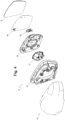
- the rear-view mirror 10 is further provided with a back plate 18 to which the blind spot indicator assembly 100 is fitted.
- a heater 19 is also provided including a heating element which in use acts as resistive heating of the mirror glass 12 as an electric current flows through.
- the heater 19 includes an adhesive for attaching the mirror glass 12 to the back plate 18.
- the blind spot indicator assembly 100 is in turn attached to the heater 19.
- the back plate 18 has a hole formed therein to allow a rear portion of the blind spot indicator assembly 100 to protrude there through.
- the blind spot indicator assembly 100 comprises a housing 110.
- the housing 110 of the blind spot indicator assembly 100 includes a first side with an aperture 120, and an inner surface.
- the light control assembly 130 is positioned to receive the light projected from the light source 150.
- the lens assembly 160 or at least a portion of the lens assembly 160 having no opaque adhesive is arranged to receive light from the light control assembly 130.
- the housing 110 of the present blind spot indicator assembly 100 has a holding area 115 for placing the first side 140a of the PCB 140 so that the second side 140b is at least substantially flush with the aperture 120.
- Said holding area 115 comprises opposite walls 115a, 115b for placing the first side 140a of the PCB 140 so that the second side 140b of the PCB 140 is at least substantially flush with the aperture 120.
- Projections 116 as shown in figure 2 may be provided in the holding area 115 to fit the PCB 140.
- the PCB 140 is fitted between said projections 116, the opposite walls 115a, 115b and the internal surface of the housing 110.
- movements of the PCB 140 with respect to the housing 110 are avoided while movements in an assembly direction D are allowed.
- a compression pressure is finally applied to the housing 110 and to the lens assembly 160 in an assembly direction D, as shown in figure 2 , perpendicular or substantially perpendicular to the lens assembly 160.
Landscapes
- Engineering & Computer Science (AREA)
- Mechanical Engineering (AREA)
- Multimedia (AREA)
- Lighting Device Outwards From Vehicle And Optical Signal (AREA)
Priority Applications (1)
| Application Number | Priority Date | Filing Date | Title |
|---|---|---|---|
| EP23383388.8A EP4578733A1 (de) | 2023-12-27 | 2023-12-27 | Totwinkelanzeigeanordnung für ein kraftfahrzeug und verfahren zur montage einer totwinkelanzeigeanordnung |
Applications Claiming Priority (1)
| Application Number | Priority Date | Filing Date | Title |
|---|---|---|---|
| EP23383388.8A EP4578733A1 (de) | 2023-12-27 | 2023-12-27 | Totwinkelanzeigeanordnung für ein kraftfahrzeug und verfahren zur montage einer totwinkelanzeigeanordnung |
Publications (1)
| Publication Number | Publication Date |
|---|---|
| EP4578733A1 true EP4578733A1 (de) | 2025-07-02 |
Family
ID=89573618
Family Applications (1)
| Application Number | Title | Priority Date | Filing Date |
|---|---|---|---|
| EP23383388.8A Pending EP4578733A1 (de) | 2023-12-27 | 2023-12-27 | Totwinkelanzeigeanordnung für ein kraftfahrzeug und verfahren zur montage einer totwinkelanzeigeanordnung |
Country Status (1)
| Country | Link |
|---|---|
| EP (1) | EP4578733A1 (de) |
Citations (9)
| Publication number | Priority date | Publication date | Assignee | Title |
|---|---|---|---|---|
| US9663027B2 (en) | 2014-02-19 | 2017-05-30 | Fico Mirrors, S.A. | Exterior rear view mirror assembly for a motor vehicle |
| US9754489B1 (en) | 2015-09-28 | 2017-09-05 | Magna Mirrors Of America, Inc. | Exterior mirror assembly with blind zone indicator |
| WO2017198491A1 (en) * | 2016-05-17 | 2017-11-23 | SMR Patents S.à.r.l. | Backing plate unit, method for producing such a backing plate unit and rear view device for a motor vehicle with such a backing plate unit |
| CN208431704U (zh) * | 2018-06-21 | 2019-01-25 | 佛山市立久光电科技有限公司 | 一种盲区警示灯 |
| CN209744281U (zh) * | 2019-04-08 | 2019-12-06 | 佛山市立久光电科技有限公司 | 一种盲区警示灯 |
| CN209776314U (zh) * | 2019-04-28 | 2019-12-13 | 上海吕巷汽车零部件有限公司 | 一种汽车盲区监测后视镜 |
| US10614719B2 (en) | 2014-09-11 | 2020-04-07 | Magna Mirrors Of America, Inc. | Exterior mirror with blind zone indicator |
| CN210822042U (zh) * | 2019-11-18 | 2020-06-23 | 重庆熠美实业发展有限公司 | 一种外后视镜盲区提示灯 |
| CN111731195A (zh) * | 2020-07-02 | 2020-10-02 | 常州九鼎车业股份有限公司 | 一种带有盲区灯的后视镜及组装方法 |
-
2023
- 2023-12-27 EP EP23383388.8A patent/EP4578733A1/de active Pending
Patent Citations (9)
| Publication number | Priority date | Publication date | Assignee | Title |
|---|---|---|---|---|
| US9663027B2 (en) | 2014-02-19 | 2017-05-30 | Fico Mirrors, S.A. | Exterior rear view mirror assembly for a motor vehicle |
| US10614719B2 (en) | 2014-09-11 | 2020-04-07 | Magna Mirrors Of America, Inc. | Exterior mirror with blind zone indicator |
| US9754489B1 (en) | 2015-09-28 | 2017-09-05 | Magna Mirrors Of America, Inc. | Exterior mirror assembly with blind zone indicator |
| WO2017198491A1 (en) * | 2016-05-17 | 2017-11-23 | SMR Patents S.à.r.l. | Backing plate unit, method for producing such a backing plate unit and rear view device for a motor vehicle with such a backing plate unit |
| CN208431704U (zh) * | 2018-06-21 | 2019-01-25 | 佛山市立久光电科技有限公司 | 一种盲区警示灯 |
| CN209744281U (zh) * | 2019-04-08 | 2019-12-06 | 佛山市立久光电科技有限公司 | 一种盲区警示灯 |
| CN209776314U (zh) * | 2019-04-28 | 2019-12-13 | 上海吕巷汽车零部件有限公司 | 一种汽车盲区监测后视镜 |
| CN210822042U (zh) * | 2019-11-18 | 2020-06-23 | 重庆熠美实业发展有限公司 | 一种外后视镜盲区提示灯 |
| CN111731195A (zh) * | 2020-07-02 | 2020-10-02 | 常州九鼎车业股份有限公司 | 一种带有盲区灯的后视镜及组装方法 |
Similar Documents
| Publication | Publication Date | Title |
|---|---|---|
| US12112638B2 (en) | Vehicular exterior rearview mirror assembly with blind zone indicator | |
| US10640047B2 (en) | Mirror reflective element sub-assembly for vehicular exterior rearview mirror assembly | |
| US7510311B2 (en) | Exterior rearview mirror for vehicles, in particular motor vehicles | |
| US6441943B1 (en) | Indicators and illuminators using a semiconductor radiation emitter package | |
| CA2367011C (en) | Indicators and illuminators using a semiconductor radiation emitter package | |
| EP4578733A1 (de) | Totwinkelanzeigeanordnung für ein kraftfahrzeug und verfahren zur montage einer totwinkelanzeigeanordnung | |
| JP2006527128A (ja) | 照明手段を内蔵したミラー組立体 | |
| US20250216051A1 (en) | Blind spot indicator assembly for a motor vehicle, method for assembling a blind spot indicator assembly, and rear-view mirror comprising said blind spot indicator assembly | |
| US12488690B2 (en) | Blind spot indicator assembly for a motor vehicle and rear-view mirror comprising said blind spot indicator assembly | |
| EP4578737A1 (de) | Rückspiegelanordnung für kraftfahrzeuge | |
| CN100522697C (zh) | 带有集成发光膜的镜子玻璃组件 | |
| US12391172B2 (en) | Blind spot indicator assembly for a motor vehicle and rear-view mirror comprising said blind spot indicator assembly | |
| CN219360937U (zh) | 防眩晕的车载后视镜 | |
| JP2020175863A (ja) | 車両用表示装置 |
Legal Events
| Date | Code | Title | Description |
|---|---|---|---|
| PUAI | Public reference made under article 153(3) epc to a published international application that has entered the european phase |
Free format text: ORIGINAL CODE: 0009012 |
|
| STAA | Information on the status of an ep patent application or granted ep patent |
Free format text: STATUS: THE APPLICATION HAS BEEN PUBLISHED |
|
| AK | Designated contracting states |
Kind code of ref document: A1 Designated state(s): AL AT BE BG CH CY CZ DE DK EE ES FI FR GB GR HR HU IE IS IT LI LT LU LV MC ME MK MT NL NO PL PT RO RS SE SI SK SM TR |
|
| RAP3 | Party data changed (applicant data changed or rights of an application transferred) |
Owner name: FICOSA AUTOMOTIVE, S.L.U. |
|
| STAA | Information on the status of an ep patent application or granted ep patent |
Free format text: STATUS: REQUEST FOR EXAMINATION WAS MADE |
|
| 17P | Request for examination filed |
Effective date: 20260102 |