EP4578722A1 - Battery charging and swapping station - Google Patents
Battery charging and swapping station Download PDFInfo
- Publication number
- EP4578722A1 EP4578722A1 EP23856312.6A EP23856312A EP4578722A1 EP 4578722 A1 EP4578722 A1 EP 4578722A1 EP 23856312 A EP23856312 A EP 23856312A EP 4578722 A1 EP4578722 A1 EP 4578722A1
- Authority
- EP
- European Patent Office
- Prior art keywords
- battery
- swap
- transfer
- battery swap
- platform
- Prior art date
- Legal status (The legal status is an assumption and is not a legal conclusion. Google has not performed a legal analysis and makes no representation as to the accuracy of the status listed.)
- Withdrawn
Links
Images


Classifications
-
- B—PERFORMING OPERATIONS; TRANSPORTING
- B60—VEHICLES IN GENERAL
- B60L—PROPULSION OF ELECTRICALLY-PROPELLED VEHICLES; SUPPLYING ELECTRIC POWER FOR AUXILIARY EQUIPMENT OF ELECTRICALLY-PROPELLED VEHICLES; ELECTRODYNAMIC BRAKE SYSTEMS FOR VEHICLES IN GENERAL; MAGNETIC SUSPENSION OR LEVITATION FOR VEHICLES; MONITORING OPERATING VARIABLES OF ELECTRICALLY-PROPELLED VEHICLES; ELECTRIC SAFETY DEVICES FOR ELECTRICALLY-PROPELLED VEHICLES
- B60L53/00—Methods of charging batteries, specially adapted for electric vehicles; Charging stations or on-board charging equipment therefor; Exchange of energy storage elements in electric vehicles
- B60L53/80—Exchanging energy storage elements, e.g. removable batteries
-
- B—PERFORMING OPERATIONS; TRANSPORTING
- B60—VEHICLES IN GENERAL
- B60L—PROPULSION OF ELECTRICALLY-PROPELLED VEHICLES; SUPPLYING ELECTRIC POWER FOR AUXILIARY EQUIPMENT OF ELECTRICALLY-PROPELLED VEHICLES; ELECTRODYNAMIC BRAKE SYSTEMS FOR VEHICLES IN GENERAL; MAGNETIC SUSPENSION OR LEVITATION FOR VEHICLES; MONITORING OPERATING VARIABLES OF ELECTRICALLY-PROPELLED VEHICLES; ELECTRIC SAFETY DEVICES FOR ELECTRICALLY-PROPELLED VEHICLES
- B60L53/00—Methods of charging batteries, specially adapted for electric vehicles; Charging stations or on-board charging equipment therefor; Exchange of energy storage elements in electric vehicles
- B60L53/30—Constructional details of charging stations
-
- B—PERFORMING OPERATIONS; TRANSPORTING
- B60—VEHICLES IN GENERAL
- B60S—SERVICING, CLEANING, REPAIRING, SUPPORTING, LIFTING, OR MANOEUVRING OF VEHICLES, NOT OTHERWISE PROVIDED FOR
- B60S5/00—Servicing, maintaining, repairing, or refitting of vehicles
- B60S5/06—Supplying batteries to, or removing batteries from, vehicles
-
- Y—GENERAL TAGGING OF NEW TECHNOLOGICAL DEVELOPMENTS; GENERAL TAGGING OF CROSS-SECTIONAL TECHNOLOGIES SPANNING OVER SEVERAL SECTIONS OF THE IPC; TECHNICAL SUBJECTS COVERED BY FORMER USPC CROSS-REFERENCE ART COLLECTIONS [XRACs] AND DIGESTS
- Y02—TECHNOLOGIES OR APPLICATIONS FOR MITIGATION OR ADAPTATION AGAINST CLIMATE CHANGE
- Y02T—CLIMATE CHANGE MITIGATION TECHNOLOGIES RELATED TO TRANSPORTATION
- Y02T10/00—Road transport of goods or passengers
- Y02T10/60—Other road transportation technologies with climate change mitigation effect
- Y02T10/70—Energy storage systems for electromobility, e.g. batteries
-
- Y—GENERAL TAGGING OF NEW TECHNOLOGICAL DEVELOPMENTS; GENERAL TAGGING OF CROSS-SECTIONAL TECHNOLOGIES SPANNING OVER SEVERAL SECTIONS OF THE IPC; TECHNICAL SUBJECTS COVERED BY FORMER USPC CROSS-REFERENCE ART COLLECTIONS [XRACs] AND DIGESTS
- Y02—TECHNOLOGIES OR APPLICATIONS FOR MITIGATION OR ADAPTATION AGAINST CLIMATE CHANGE
- Y02T—CLIMATE CHANGE MITIGATION TECHNOLOGIES RELATED TO TRANSPORTATION
- Y02T10/00—Road transport of goods or passengers
- Y02T10/60—Other road transportation technologies with climate change mitigation effect
- Y02T10/7072—Electromobility specific charging systems or methods for batteries, ultracapacitors, supercapacitors or double-layer capacitors
Definitions
- the invention relates to the technical field of battery swapping, and in particular to a battery charging and swapping station.
- Battery swapping is a rapid energy replenishment method for electric vehicles, which specifically involves removing a traction battery of an electric vehicle and immediately swapping the traction battery for another one through a battery swapping device.
- a battery charging and swapping station is a facility for implementing swapping of traction batteries of electric vehicles.
- the conveying mechanism 5 is located at a left side of the battery swap mechanism 4
- the temporary storage mechanism 6 is located at a right side of the battery swap mechanism 4
- the conveying mechanism 5 carries and conveys a fully charged battery removed from the stacker 22 to the left side of the battery swap mechanism 4 to stand by.
- the drained battery on the battery swap mechanism 4 is transferred to the temporary storage mechanism 6 located on the right side of the battery swap mechanism, and then a fully charged battery carried on the conveying mechanism 5 is transferred to the battery swap mechanism 4.
- the drained battery on the temporary storage mechanism 6 is transferred first to the battery swap mechanism 4, and then to the conveying mechanism 5.
- the conveying mechanism 5 conveys the drained battery to the stacker 22 and brings back a fully charged battery, and if a new vehicle is already parked on the battery swap platform 1 at this time, the fully charged battery on the conveying mechanism 5 can be transferred to the battery swap mechanism 4 after the battery swap mechanism 4 dismounts the drained battery from the vehicle and transfers the drained battery to the temporary storage mechanism 6.
- two battery racks 21 are arranged in the container 23 of the battery compartment 2, and the stacker 22 is located between the two battery racks 21.
- the opening 231 in communication with the battery swap channel 3 is preferably arranged below the battery rack 21 close to the battery swap platform 1.
- the battery swap mechanism 4 of the invention includes a first fixation member 41, a lifting assembly (not shown in the figures), a battery bearing platform 42 and a locking and unlocking assembly 43.
- the lifting assembly has a bottom end fixedly connected to the first fixation member 41 and a top end fixedly connected to the battery bearing platform 42, and can lift the battery bearing platform 42 to a battery swap position, the locking and unlocking assembly 43 is mounted on the battery bearing platform 42, and the locking and unlocking assembly 43 can dismount and mount a battery.
- the battery bearing platform 42 and the locking and unlocking assembly 43 mounted on the battery bearing platform 42 are lifted together by the lifting assembly to the battery swap position, the locking and unlocking assembly 43 loosens fasteners (typically bolts) used to fasten the battery, the drained battery automatically falls on the battery bearing platform 42, and the lifting assembly then lowers the battery bearing platform 42.
- fasteners typically bolts
- lifting assembly and the locking and unlocking assembly 43 are not limited in the invention, and those skilled in the art may employ any structural form of the lifting assembly and the locking and unlocking assembly 43 existing in the battery swap mechanism in the prior art.
- the battery swap mechanism 4 of the invention further includes a first driving assembly (not shown in the figures) and a first transfer member that are mounted to the first fixation member 41.
- the first transfer member can carry a battery
- the first driving assembly is connected to the first transfer member and can drive the first transfer member to move, so as to transfer a battery located on the first transfer member to the conveying mechanism 5 or the temporary storage mechanism 6.
- the first driving assembly includes an electric motor and a gear transmission system
- the first transfer member includes a plurality of first transfer rollers 44, the plurality of first transfer rollers 44 being divided into two rows and located on two sides of the battery bearing platform 42, respectively, and a plurality of first transfer rollers 44 of each row being distributed at intervals in a length direction of the battery swap channel 3.
- the electric motor is connected to the plurality of first transfer rollers 44 via the gear transmission system and can drive the plurality of first transfer rollers 44 to rotate synchronously.
- a top surface of the battery bearing platform 42 is slightly lower than top surfaces of the first transfer rollers 44, a drained battery falls on the first transfer rollers 44 as the battery bearing platform 42 descends, the electric motor can drive the plurality of first transfer rollers 44 to rotate clockwise by means of the gear transmission system so as to transfer the drained battery located on the first transfer rollers 44 to the temporary storage mechanism 6, and the electric motor can also drive the plurality of first transfer rollers 44 to rotate counterclockwise by means of the gear transmission system so as to transfer the drained battery located on the first transfer rollers 44 to the conveying mechanism 5.
- the fully charged battery can be transferred first to the first transfer rollers 44, and in the process of the lifting assembly lifting the battery bearing platform 42 upwardly, the fully charged battery located on the first transfer rollers 44 is lifted by the battery bearing platform 42.
- the first driving assembly is not limited to the above structural form of the "electric motor + gear transmission system," for example, the first driving assembly may also be configured as “an electric motor + a gear and rack transmission system", “an electric motor + a sprocket and chain transmission system” and the like.
- the first transfer member is also not limited to the above structural form of the plurality of transfer rollers, for example, the first transfer member may also be configured as a conveyor belt, a transfer plate and the like.
- the conveying mechanism 5 of the invention includes a conveying vehicle 51 and a lift (not shown in the figure) mounted to the conveying vehicle 51.
- the conveying vehicle 51 can reciprocate along the battery swap channel 3 between the battery compartment 2 and the battery swap mechanism 4.
- the lift can drive a battery to move vertically relative to the conveying vehicle 51 in a vertical direction.
- the conveying mechanism 5 of the invention further includes a horizontal rail 53 mounted in the battery swap channel 3, the horizontal rail 53 has one end extending to below the battery compartment 2, and the horizontal rail 53 has the other end extending to the battery swap mechanism 4.
- the conveying vehicle 51 is mounted on the horizontal rail 53 and can move along the horizontal rail 53.
- the third driving assembly has the same structure as the first driving assembly, and includes an electric motor and a gear transmission system
- the third transfer member includes a plurality of third transfer rollers 62, the plurality of third transfer rollers 62 being divided into two rows, and a plurality of third transfer rollers 62 on each row being distributed at intervals in a length direction of the battery swap channel 3.
- the electric motor is connected to the plurality of third transfer rollers 62 via the gear transmission system and can drive the plurality of third transfer rollers 62 to rotate synchronously.
Landscapes
- Engineering & Computer Science (AREA)
- Mechanical Engineering (AREA)
- Power Engineering (AREA)
- Transportation (AREA)
- Arrangement Or Mounting Of Propulsion Units For Vehicles (AREA)
- Charge And Discharge Circuits For Batteries Or The Like (AREA)
Abstract
Description
- The present application claims the priority to Chinese Patent Application No.
CN202222242248.1, filed on August 24, 2022 - The invention relates to the technical field of battery swapping, and in particular to a battery charging and swapping station.
- Battery swapping is a rapid energy replenishment method for electric vehicles, which specifically involves removing a traction battery of an electric vehicle and immediately swapping the traction battery for another one through a battery swapping device. A battery charging and swapping station is a facility for implementing swapping of traction batteries of electric vehicles.
- The existing battery charging and swapping stations mainly have the following arrangement forms. In a first type of battery charging and swapping station, which is of a lifting type, a lifting mechanism is mounted to a battery swap platform, and when a vehicle is parked on the battery swap platform, the vehicle is lifted by the lifting mechanism to provide a battery swap space for a battery swap device, which results in longer battery swapping time and safety hazards due to the need to lift the vehicle. In a second type of battery charging and swapping station, a support frame is mounted below a battery swap platform to raise the battery swap platform, and this type of battery charging and swapping station requires a long ramp to connect to the battery swap platform, which results in increase of the area occupied by the battery charging and swapping station and limits site selection options.
- A patent with the publication No.
CN 108216150 A discloses a battery charging and swapping station for an electric vehicle, the battery charging and swapping station including a plurality of battery swapping positions, and each battery swapping position including a positioning platform higher than a wheel travel surface and an underground compartment below the wheel travel surface, where the positioning platform is located above the underground compartment; and a battery storage area and a battery swap mechanism are provided in the underground compartment, the battery storage area being configured to store battery packs, and the battery swap mechanism being configured to dismount a first battery pack from the electric vehicle and store the first battery pack in the battery storage area, as well as to obtain a second battery pack from the battery storage area and mount the second battery pack to the aforementioned electric vehicle. - In the battery charging and swapping station disclosed in the above patent, although there is no need to lift a vehicle or provide a long ramp, the capital construction workload for the battery charging and swapping station is exceptionally large, and the construction difficulty is high, which greatly increases the construction costs of the battery charging and swapping station.
- Therefore, a new technical solution is needed in the art to solve the above problem.
- The invention aims to solve the above technical problem, that is, to solve the problem that the layout of the existing battery charging and swapping station is not ideal.
- In a first aspect, the invention provides a battery charging and swapping station, including a battery swap platform, a battery compartment and a battery swap device, the battery compartment including a battery rack and a battery transfer mechanism arranged side by side, the battery swap platform being capable of carrying a vehicle that requires a battery swap, the battery rack being configured to store batteries, the battery transfer mechanism being capable of transferring a battery between the battery rack and the battery swap device, the battery swap device being capable of dismounting, mounting and conveying a battery, where the battery swap platform and the battery rack are both located above ground, and the battery swap device is mounted within a battery swap channel located below the ground, where the battery swap channel extends from below the battery swap platform towards the battery compartment, a total length of the battery swap channel in an extension direction is less than a total length of the battery charging and swapping station in the direction, and a length of the battery swap channel extending below the battery compartment allows accommodation of one battery.
- In a preferred technical solution of the battery charging and swapping station described above, the battery swap device includes: a battery swap mechanism located below the battery swap platform, the battery swap mechanism being capable of dismounting and mounting a battery; a conveying mechanism capable of conveying a battery between the battery transfer mechanism and the battery swap mechanism; and a temporary storage mechanism located on a side of the battery swap mechanism away from the conveying mechanism, the temporary storage mechanism being configured to temporarily store a fully charged battery conveyed by the conveying mechanism from the battery transfer mechanism or temporarily store a drained battery dismounted from a vehicle by the battery swap mechanism.
- In a preferred technical solution of the battery charging and swapping station described above, the battery swap mechanism includes a first fixation member, a lifting assembly, a battery bearing platform, and a locking and unlocking assembly, where the lifting assembly has a bottom end fixedly connected to the first fixation member and a top end fixedly connected to the battery bearing platform, and is capable of lifting the battery bearing platform to a battery swap position, and the locking and unlocking assembly is mounted on the battery bearing platform, and is capable of dismounting and mounting a battery.
- In a preferred technical solution of the battery charging and swapping station described above, the battery swap mechanism further includes a first driving assembly and a first transfer member that are mounted to the first fixation member, the first transfer member being capable of carrying a battery, and the first driving assembly being connected to the first transfer member and being capable of driving the first transfer member to move, so as to transfer a battery located on the first transfer member to the conveying mechanism or the temporary storage mechanism.
- In a preferred technical solution of the battery charging and swapping station described above, the conveying mechanism includes a conveying vehicle and a lift mounted to the conveying vehicle, the conveying vehicle being capable of reciprocating along the battery swap channel between the battery transfer mechanism and the battery swap mechanism, and the lift being capable of driving a battery to move vertically relative to the conveying vehicle in a vertical direction.
- In a preferred technical solution of the battery charging and swapping station described above, the conveying mechanism further includes a second driving assembly and a second transfer member that are mounted to the lift, the second transfer member being capable of carrying a battery, and the second driving assembly being connected to the second transfer member and being capable of driving the second transfer member to move, so as to transfer a battery located on the second transfer member to the battery swap mechanism.
- In a preferred technical solution of the battery charging and swapping station described above, the conveying mechanism further includes a horizontal rail mounted in the battery swap channel, the horizontal rail having one end extending to the transfer mechanism and the other end extending to the battery swap mechanism, and the conveying vehicle is mounted on the horizontal rail and is movable along the horizontal rail.
- In a preferred technical solution of the battery charging and swapping station described above, the temporary storage mechanism includes a second fixation member, and a third driving assembly and a third transfer member that are mounted to the second fixation member, the third transfer member being capable of carrying a battery, and the third driving assembly being connected to the third transfer member and being capable of driving the third transfer member to move, so as to transfer a battery located on the third transfer member to the battery swap mechanism.
- In a preferred technical solution of the battery charging and swapping station described above, the battery compartment further includes a container in which the battery rack and the battery transfer mechanism are mounted, and an opening is provided in a bottom plate of the container and is in communication with the battery swap channel.
- In a preferred technical solution of the battery charging and swapping station described above, the battery rack is located between the battery transfer mechanism and the battery swap platform, and the battery swap channel extends to below the battery rack; or the battery transfer mechanism is located between the battery rack and the battery swap platform, and a lower portion of the battery transfer mechanism is located within the battery swap channel; or two of the battery racks are provided, the battery transfer mechanism is located between the two battery racks, and the battery swap channel extends to below the battery rack which is close to the battery swap platform.
- With the foregoing technical solutions, the design of layout of the battery charging and swapping station is optimized in the invention by providing the battery swap channel, which has an extension length less than the total length of the battery charging and swapping station, below the ground to connect the battery compartment and the battery swap platform that are located above the ground, and by mounting the battery swap device in the battery swap channel, such that the vehicle that requires a battery swap can be parked on the battery swap platform, without the need to lift the vehicle or to provide a support frame below the battery swap platform to raise the battery swap platform. In addition, compared with the battery charging and swapping station for an electric vehicle disclosed in the patent with the publication No.
CN 108216150 A , the battery charging and swapping station of the invention does not require excavating the entire area below the battery charging and swapping station, and only partial excavation is needed, resulting in a smaller capital construction workload, lower construction difficulty, and significantly reduced construction costs of the battery charging and swapping station. - Further, the battery charging and swapping station of the invention can improve the efficiency of swapping of the battery charging and swapping station and reduce the swapping time by providing a temporary storage mechanism capable of temporarily storing a battery in the battery swap channel.
- Preferred implementations of the invention will be described below with reference to the accompanying drawings, in which:
-
FIG. 1 is a schematic diagram of a battery charging and swapping station of the invention; -
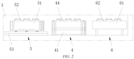
FIG. 2 is a partially enlarged schematic diagram of area A inFIG. 1 ; and -
FIG. 3 is a schematic diagram of a battery swap mechanism of the invention. - 1. Battery swap platform; 2. Battery compartment; 21. Battery rack; 22. Stacker; 23. Container; 211. Storage space; 231. Opening; 3. Battery swap channel; 4. Battery swap mechanism; 41. First fixation member; 42. Battery bearing platform; 43. Locking and unlocking assembly; 44. First transfer roller; 5. Conveying mechanism; 51. Conveying vehicle; 52. Second transfer roller; 53. Horizontal track; 6. Temporary storage mechanism; 61. Second fixation member; 62. Third transfer roller; 7. Ground.
- Preferred implementations of the invention will be described below with reference to the accompanying drawings. Those skilled in the art should understand that these implementations are merely used to explain the technical principles of the invention, and are not intended to limit the scope of protection of the invention.
- It should be noted that, in the description of the invention, the terms that indicate the direction or positional relationship, such as "left", "right", "upper", "lower", "top", and "bottom" are based on the direction or positional relationship shown in the figures, which is merely for ease of description instead of indicating or implying that the device or element must have a particular orientation and be constructed and operated in a particular orientation, and therefore, should not be construed as limiting the invention.
- In addition, it should also be noted that, in the description of the invention, the terms "arrange", "connect" and "mount" should be interpreted in a broad sense unless explicitly defined and limited otherwise. For example, a connection may be a fastened connection, a detachable connection, or an integral connection. For those skilled in the art, the specific meanings of the foregoing terms in the invention can be interpreted according to a specific situation.
- Specifically, as shown in
FIG. 1 , the invention provides a battery charging and swapping station for replacing a traction battery for a vehicle. The battery charging and swapping station of the invention mainly includes abattery swap platform 1, abattery compartment 2 and a battery swap device. Thebattery swap platform 1 can carry a vehicle that requires a battery swap, thebattery compartment 2 is mainly configured to store batteries, and the battery swap device is mainly configured to dismount, mount and convey a battery. - After entering the battery charging and swapping station, a vehicle that requires a battery swap can be guided by a working person to park at a designated position on the
battery swap platform 1, or the vehicle automatically parks at the designated position on thebattery swap platform 1, and the battery swap device dismounts a drained battery from the vehicle and conveys the drained battery to thebattery compartment 2, and then brings back a fully charged battery from thebattery compartment 2 and mounts the fully charged battery to the vehicle. - With continued reference to
FIG. 1 , the battery compartment of the invention includes abattery rack 21 and a battery transfer mechanism which, in the invention, is astacker 22. Thebattery rack 21 is configured to store batteries, and thestacker 22 is configured to transfer a battery between thebattery rack 21 and the battery swap device. - The
battery swap platform 1, thebattery rack 21 and thestacker 22 are all located aboveground 7, and the battery swap device is mounted in abattery swap channel 3 located below theground 7. Thebattery swap channel 3 extends from below thebattery swap platform 1 towards thebattery compartment 2, and a total length of thebattery swap channel 3 in an extension direction (i.e., a length of thebattery swap channel 3 in a left-right direction inFIG. 1 ) is less than a total length of the battery charging and swapping station in this direction (i.e., the sum of lengths of thebattery swap platform 1 and thebattery compartment 2 in the left-right direction inFIG. 1 ). A length of thebattery swap channel 3 extending below thebattery compartment 2 allows accommodation of one battery. - The design of layout of the battery charging and swapping station is optimized in the invention by providing the
battery swap channel 3, which has an extension length less than the total length of the battery charging and swapping station, below theground 7 to connect thebattery compartment 2 and thebattery swap platform 1 that are located above theground 7, and by mounting the battery swap device in thebattery swap channel 3, such that the vehicle that requires a battery swap can be parked on thebattery swap platform 1, without the need to lift the vehicle or to provide a support frame below thebattery swap platform 1 to raise thebattery swap platform 1. - In addition, compared with the battery charging and swapping station for an electric vehicle disclosed in the patent with the publication No.
CN 108216150 A , the battery charging and swapping station of the invention does not require excavating the entire area below the battery charging and swapping station, and only partial excavation is needed, resulting in a smaller capital construction workload, lower construction difficulty, and significantly reduced construction costs. - It should be noted that, in practical applications, those skilled in the art can configure the battery swap device as a rail guided vehicle (RGV), as an automated guided vehicle (AGV), or the like, and such adjustments and changes to the specific type of the battery swap device do not deviate from the principle and scope of the invention, and should fall into the scope of protection of the invention.
- In addition, in the implementation below, although the battery transfer mechanism is illustrated with the
stacker 22 as an example, this is not intended to limit the scope of the invention, and any mechanism that can transfer a battery between thebattery rack 21 and the battery swap device may be a substitute for thestacker 22. - Preferably, as shown in
FIGs. 1 and2 , the battery swap device of the invention includes abattery swap mechanism 4, a conveyingmechanism 5 and atemporary storage mechanism 6. - The
battery swap mechanism 4 is located below thebattery swap platform 1, and thebattery swap mechanism 4 can dismount and mount a battery. The conveyingmechanism 5 can convey the battery between thestacker 22 and thebattery swap mechanism 4. Thetemporary storage mechanism 6 is located at a side of thebattery swap mechanism 4 away from the conveyingmechanism 5, and thetemporary storage mechanism 6 is configured to temporarily store a fully charged battery conveyed by the conveyingmechanism 5 from thestacker 22 or to temporarily store a drained battery dismounted from a vehicle by thebattery swap mechanism 4. - Providing the
temporary storage mechanism 6 can improve the efficiency of the battery swap and reduce the battery swap time. - For example, the conveying
mechanism 5 is located at a left side of thebattery swap mechanism 4, thetemporary storage mechanism 6 is located at a right side of thebattery swap mechanism 4, and the conveyingmechanism 5 carries and conveys a fully charged battery removed from thestacker 22 to the left side of thebattery swap mechanism 4 to stand by. - After a drained battery of the vehicle is dismounted by the
battery swap mechanism 4, the drained battery on thebattery swap mechanism 4 is transferred to thetemporary storage mechanism 6 located on the right side of the battery swap mechanism, and then a fully charged battery carried on the conveyingmechanism 5 is transferred to thebattery swap mechanism 4. After the fully charged battery is mounted to the vehicle by thebattery swap mechanism 4, the drained battery on thetemporary storage mechanism 6 is transferred first to thebattery swap mechanism 4, and then to the conveyingmechanism 5. - The conveying
mechanism 5 conveys the drained battery to thestacker 22 and brings back a fully charged battery, and if a new vehicle is already parked on thebattery swap platform 1 at this time, the fully charged battery on the conveyingmechanism 5 can be transferred to thebattery swap mechanism 4 after thebattery swap mechanism 4 dismounts the drained battery from the vehicle and transfers the drained battery to thetemporary storage mechanism 6. - If no new vehicle is parked on the
battery swap platform 1 at this time, the fully charged battery on the conveyingmechanism 5 can be first transferred to thebattery swap mechanism 4, and then transferred to thetemporary storage mechanism 6 for temporary storage. After the drained battery on the vehicle is dismounted by thebattery swap mechanism 4 and transferred to the conveyingmechanism 5, the fully charged battery on thetemporary storage mechanism 6 is then transferred to thebattery swap mechanism 4, and the drained battery is directly conveyed by the conveyingmechanism 5 to thestacker 22. - Preferably, as shown in
FIG. 1 , thebattery compartment 2 of the invention further includes acontainer 23, and thebattery rack 21 and thestacker 22 are mounted in thecontainer 23. Anopening 231 is provided in a bottom plate of thecontainer 23, theopening 231 is in communication with thebattery swap channel 3, thebattery rack 21 is configured to store batteries, and thestacker 22 can transfer a battery between thebattery rack 21 and the conveyingmechanism 5. - For example, the
battery rack 21 has a plurality ofstorage spaces 211 for storing batteries, theopening 231 in communication with thebattery swap channel 3 is located below thebattery rack 21, the conveyingmechanism 5 can move along thebattery swap channel 3 to theopening 231, and thestacker 22 can access and transfer a fully charged battery located on thestorage space 211 to the conveyingmechanism 5 located at theopening 231, or can access and transfer a battery located on the conveyingmechanism 5 to thestorage space 211 of thebattery rack 21. - Preferably, as shown in
FIG. 1 , in the invention, twobattery racks 21 are arranged in thecontainer 23 of thebattery compartment 2, and thestacker 22 is located between the two battery racks 21. - The
opening 231 in communication with thebattery swap channel 3 is preferably arranged below thebattery rack 21 close to thebattery swap platform 1. - Preferably, as shown in
FIGs. 2 and3 , thebattery swap mechanism 4 of the invention includes afirst fixation member 41, a lifting assembly (not shown in the figures), abattery bearing platform 42 and a locking and unlockingassembly 43. - The lifting assembly has a bottom end fixedly connected to the
first fixation member 41 and a top end fixedly connected to thebattery bearing platform 42, and can lift thebattery bearing platform 42 to a battery swap position, the locking and unlockingassembly 43 is mounted on thebattery bearing platform 42, and the locking and unlockingassembly 43 can dismount and mount a battery. - When a battery is required to be dismounted, the
battery bearing platform 42 and the locking and unlockingassembly 43 mounted on thebattery bearing platform 42 are lifted together by the lifting assembly to the battery swap position, the locking and unlockingassembly 43 loosens fasteners (typically bolts) used to fasten the battery, the drained battery automatically falls on thebattery bearing platform 42, and the lifting assembly then lowers thebattery bearing platform 42. - It should be noted that, in practical applications, those skilled in the art can configure the
first fixation member 41 as a fixation housing, a fixation bracket, a fixation block or the like, and such adjustments and changes to the specific structural form of thefirst fixation member 41 do not deviate from the principle and scope of the invention, and should fall into the scope of protection of the invention. - It should be further noted that the specific structural forms of the lifting assembly and the locking and unlocking
assembly 43 are not limited in the invention, and those skilled in the art may employ any structural form of the lifting assembly and the locking and unlockingassembly 43 existing in the battery swap mechanism in the prior art. - Preferably, as shown in
FIGs. 2 and3 , thebattery swap mechanism 4 of the invention further includes a first driving assembly (not shown in the figures) and a first transfer member that are mounted to thefirst fixation member 41. The first transfer member can carry a battery, and the first driving assembly is connected to the first transfer member and can drive the first transfer member to move, so as to transfer a battery located on the first transfer member to the conveyingmechanism 5 or thetemporary storage mechanism 6. - For example, the first driving assembly includes an electric motor and a gear transmission system, and the first transfer member includes a plurality of
first transfer rollers 44, the plurality offirst transfer rollers 44 being divided into two rows and located on two sides of thebattery bearing platform 42, respectively, and a plurality offirst transfer rollers 44 of each row being distributed at intervals in a length direction of thebattery swap channel 3. The electric motor is connected to the plurality offirst transfer rollers 44 via the gear transmission system and can drive the plurality offirst transfer rollers 44 to rotate synchronously. - In a non-lifted state, a top surface of the
battery bearing platform 42 is slightly lower than top surfaces of thefirst transfer rollers 44, a drained battery falls on thefirst transfer rollers 44 as thebattery bearing platform 42 descends, the electric motor can drive the plurality offirst transfer rollers 44 to rotate clockwise by means of the gear transmission system so as to transfer the drained battery located on thefirst transfer rollers 44 to thetemporary storage mechanism 6, and the electric motor can also drive the plurality offirst transfer rollers 44 to rotate counterclockwise by means of the gear transmission system so as to transfer the drained battery located on thefirst transfer rollers 44 to the conveyingmechanism 5. - After the fully charged battery is conveyed by the conveying
mechanism 5, the fully charged battery can be transferred first to thefirst transfer rollers 44, and in the process of the lifting assembly lifting thebattery bearing platform 42 upwardly, the fully charged battery located on thefirst transfer rollers 44 is lifted by thebattery bearing platform 42. - It should be noted that the first driving assembly is not limited to the above structural form of the "electric motor + gear transmission system," for example, the first driving assembly may also be configured as "an electric motor + a gear and rack transmission system", "an electric motor + a sprocket and chain transmission system" and the like. Moreover, the first transfer member is also not limited to the above structural form of the plurality of transfer rollers, for example, the first transfer member may also be configured as a conveyor belt, a transfer plate and the like. Such adjustments and changes to the specific structural forms of the first driving assembly and the first transfer member do not deviate from the principle and scope of the invention, and should fall into the scope of protection of the invention.
- Preferably, as shown in
FIG. 2 , the conveyingmechanism 5 of the invention includes a conveyingvehicle 51 and a lift (not shown in the figure) mounted to the conveyingvehicle 51. The conveyingvehicle 51 can reciprocate along thebattery swap channel 3 between thebattery compartment 2 and thebattery swap mechanism 4. The lift can drive a battery to move vertically relative to the conveyingvehicle 51 in a vertical direction. - After the conveying
vehicle 51 carries a drained battery dismounted from a vehicle and moves to below theopening 231 of thebattery compartment 2, the lift carries the drained battery and ascends to theopening 231, thestacker 22 first removes the drained battery and places the drained battery on thestorage space 211 of thebattery rack 21, and then takes a fully charged battery from thestorage space 211 of thebattery rack 21 and places the fully charged battery on the lift, the lift carries the fully charged battery and descends, and the conveyingvehicle 51 conveys the fully charged battery to thebattery swap mechanism 4. - It should be noted that the specific structural form of the lift is not defined in the invention, for example, the lift may be configured as a structural form of a linear electric motor + a lifting plate, the linear electric motor being connected to the lifting plate and being capable of driving the lifting plate to move vertically in a vertical direction, or the lift may also be configured as an electric motor + a gear and a rack meshing with each other + a lifting plate, the electric motor being connected to the gear, the rack being fixedly connected to the lifting plate and extending in the vertical direction, the electric motor driving the gear to rotate, and the gear driving the rack and the lifting plate to move vertically, etc., as long as a battery can be lifted by the lift.
- Preferably, as shown in
FIG. 2 , the conveyingmechanism 5 of the invention further includes a second driving assembly (not shown in the figures) and a second transfer member that are mounted to the conveyingvehicle 51. The second transfer member can carry a battery, and the second driving assembly is connected to the second transfer member and can drive the second transfer member to move, so as to transfer a battery located on the second transfer member to thebattery swap mechanism 4. - For example, the second driving assembly has the same structure as the first driving assembly, and includes an electric motor and a gear transmission system, and the second transfer member includes a plurality of
second transfer rollers 52, the plurality ofsecond transfer rollers 52 being divided into two rows and located on two sides of the lift, respectively, a plurality ofsecond transfer rollers 52 on each row being distributed at intervals in a length direction of thebattery swap channel 3. The electric motor is connected to the plurality ofsecond transfer rollers 52 via the gear transmission system, and can drive the plurality ofsecond transfer rollers 52 to rotate synchronously. - In a non-lifted state, a top surface of the lift is slightly lower than top surfaces of the
second transfer rollers 52, and a fully charged battery falls on thesecond transfer rollers 52 as the lift descends, the electric motor can drive the plurality ofsecond transfer rollers 52 to rotate clockwise by means of the gear transmission system, so as to transfer the fully charged battery located on thesecond transfer rollers 52 to thebattery swap mechanism 4. - A drained battery transferred from the
battery swap mechanism 4 is placed on thesecond transfer rollers 52, and after the conveyingmechanism 5 conveys the drained battery to below thebattery compartment 2, the lift is operated, and during lifting, the lift jacks up the drained battery located on thesecond transfer rollers 52 and lifts the drained battery to theopening 231 of thebattery compartment 2. - It should be noted that, similar to the first driving assembly, the second driving assembly is also not limited to the above structural form of the "electric motor + gear transmission system," for example, the second driving assembly may also be configured as an "electric motor + gear and rack transmission system", an "electric motor + sprocket and chain transmission system" and the like. Moreover, the second transfer member is also not limited to the above structural form of the plurality of transfer rollers, for example, the second transfer member may also be configured as a conveyor belt, a transfer plate and the like. Such adjustments and changes to the specific structural forms of the second driving assembly and the second transfer member do not deviate from the principle and scope of the invention, and should fall into the scope of protection of the invention.
- Preferably, as shown in
FIGs. 1 and2 , the conveyingmechanism 5 of the invention further includes ahorizontal rail 53 mounted in thebattery swap channel 3, thehorizontal rail 53 has one end extending to below thebattery compartment 2, and thehorizontal rail 53 has the other end extending to thebattery swap mechanism 4. The conveyingvehicle 51 is mounted on thehorizontal rail 53 and can move along thehorizontal rail 53. - It should be noted that the specific form of the conveying
mechanism 5 is not limited to only one form, and those skilled in the art can adjust the configuration thereof, as long as the function of conveying a battery between thebattery compartment 2 and thebattery swap mechanism 4 can be realized. For example, the conveying mechanism may also be provided in the form of a conveyor belt + a lift, the conveyor belt being located between thebattery compartment 2 and thebattery swap mechanism 4, and the lift being located below the battery compartment. The conveyor belt may also be replaced with transfer rollers. - Preferably, as shown in
FIG. 2 , thetemporary storage mechanism 6 of the invention includes asecond fixation member 61, and a third driving assembly (not shown in the figure) and a third transfer member that are mounted to thesecond fixation member 61. The third transfer member can carry a battery, and the third driving assembly is connected to the third transfer member and can drive the third transfer member to move, so as to transfer a battery located on the third transfer member to thebattery swap mechanism 4. - For example, the third driving assembly has the same structure as the first driving assembly, and includes an electric motor and a gear transmission system, and the third transfer member includes a plurality of
third transfer rollers 62, the plurality ofthird transfer rollers 62 being divided into two rows, and a plurality ofthird transfer rollers 62 on each row being distributed at intervals in a length direction of thebattery swap channel 3. The electric motor is connected to the plurality ofthird transfer rollers 62 via the gear transmission system and can drive the plurality ofthird transfer rollers 62 to rotate synchronously. - A battery, which may be a fully charged battery or a drained battery, temporarily stored on the
temporary storage mechanism 6 is placed on thethird transfer rollers 62, and when the battery is required to be moved to thebattery swap mechanism 4, the electric motor is operated, and the electric motor can drive the plurality ofthird transfer rollers 62 to rotate counterclockwise by means of the gear transmission system, so as to transfer the battery located on thethird transfer rollers 62 to thebattery swap mechanism 4. - It should be noted that, similar to the first driving assembly, the third driving assembly is also not limited to the above structural form of the "electric motor + gear transmission system," for example, the third driving assembly may also be configured as an "electric motor + gear and rack transmission system", an "electric motor + sprocket and chain transmission system" and the like. Moreover, the third transfer member is also not limited to the above structural form of the plurality of transfer rollers, for example, the third transfer member may also be configured as a conveyor belt, a transfer plate and the like. Such adjustments and changes to the specific structural forms of the third driving assembly and the third transfer member do not deviate from the principle and scope of the invention, and should fall into the scope of protection of the invention.
- In addition, it should be noted that in practical applications, those skilled in the art can configure the
second fixation member 61 as a fixation housing, a fixation bracket, a fixation block or the like, and such adjustments and changes of the specific structural form of thesecond fixation member 61 do not deviate from the principle and scope of the invention, and should fall into the scope of protection of the invention. - It should be noted that although the above implementation is described in conjunction with two
battery racks 21 being provided in thebattery compartment 2, the arrangement is not limited to only one form, and those skilled in the art can select the number ofbattery racks 21 according to actual application scenarios and the relationship between thebattery rack 21 and thestacker 22. - For example, in an alternative implementation, one
battery rack 21 and onestacker 22 may be provided in thebattery compartment 2, thebattery rack 21 is arranged between thestacker 22 and thebattery swap platform 1, and the rest of the arrangement is the same as the above embodiment and will not be repeated herein. - In another alternative implementation, one
battery rack 21 and onestacker 22 may be provided in thebattery compartment 2, but thestacker 22 is located between thebattery rack 21 and thebattery swap platform 1. In this case, a lower portion of thestacker 22 can be arranged in thebattery swap channel 3, for example, the bottom of thestacker 22 is directly fixed in thebattery swap channel 3, or thestacker 22 is fixed in thebattery compartment 2 but a lifting rail of the stacker extends downwardly into thebattery swap channel 3. In this arrangement, the lift on the conveyingmechanism 5 may be omitted, thestacker 22 directly interfaces with thesecond transfer rollers 52, thereby simplifying the structure of the conveyingmechanism 5. - It should also be noted that, in the above implementation, although the length of the
battery swap channel 3 is described in conjunction with extending from a side edge of a side of thebattery swap platform 1 away from thebattery compartment 2 to below thebattery compartment 2, the length of thebattery swap channel 3 is not limited thereto, and can be adjusted by those skilled in the art, as long as the adjusted technical solution satisfies the condition that the total length of thebattery swap channel 3 is less than the total length of the battery charging and swapping station in this direction. - For example, when the battery swap device includes only the
battery swap mechanism 4 and the conveyingmechanism 5, without thetemporary storage mechanism 6 being provided, the length of thebattery swap channel 3 can be shortened to extend from a right side position of thebattery swap mechanism 4 to below thebattery compartment 2, thereby shortening the excavation length of thebattery swap channel 3, and further reducing the construction difficulty and construction costs. - Those skilled in the art should understand that, although some of the embodiments herein include some but not other features included in other embodiments, the combination of the features of different embodiments means being within the scope of the present application and forms different embodiments. For example, in the claims of the invention, any one of the claimed embodiments can be used in any combination.
- Heretofore, the technical solutions of the invention have been described with reference to the preferred implementations shown in the accompanying drawings. However, those skilled in the art can readily understand that the scope of protection of the invention is apparently not limited to these specific implementations. Without departing from the principles of the invention, those skilled in the art may make equivalent changes or replacements to related technical features. The technical solutions obtained after these changes or replacements fall within the scope of protection of the invention.
Claims (10)
- A battery charging and swapping station, comprising a battery swap platform, a battery compartment and a battery swap device, the battery compartment comprising a battery rack and a battery transfer mechanism arranged side by side, the battery swap platform being capable of carrying a vehicle that requires a battery swap, the battery rack being configured to store batteries, the battery transfer mechanism being capable of transferring a battery between the battery rack and the battery swap device, the battery swap device being capable of dismounting, mounting and conveying a battery, wherein
the battery swap platform and the battery rack are both located above ground, and the battery swap device is mounted within a battery swap channel located below the ground, wherein the battery swap channel extends from below the battery swap platform towards the battery compartment, a total length of the battery swap channel in an extension direction is less than a total length of the battery charging and swapping station in the direction, and a length of the battery swap channel extending below the battery compartment allows accommodation of one battery. - The battery charging and swapping station according to claim 1, wherein the battery swap device comprises:a battery swap mechanism located below the battery swap platform, the battery swap mechanism being capable of dismounting and mounting a battery;a conveying mechanism capable of conveying a battery between the battery transfer mechanism and the battery swap mechanism; anda temporary storage mechanism located on a side of the battery swap mechanism away from the conveying mechanism, the temporary storage mechanism being configured to temporarily store a fully charged battery conveyed by the conveying mechanism from the battery transfer mechanism or temporarily store a drained battery dismounted from a vehicle by the battery swap mechanism.
- The battery charging and swapping station according to claim 2, wherein the battery swap mechanism comprises a first fixation member, a lifting assembly, a battery bearing platform, and a locking and unlocking assembly, wherein the lifting assembly has a bottom end fixedly connected to the first fixation member and a top end fixedly connected to the battery bearing platform, and is capable of lifting the battery bearing platform to a battery swap position, and the locking and unlocking assembly is mounted on the battery bearing platform, and is capable of dismounting and mounting a battery.
- The battery charging and swapping station according to claim 3, wherein the battery swap mechanism further comprises a first driving assembly and a first transfer member that are mounted to the first fixation member, the first transfer member being capable of carrying a battery, and the first driving assembly being connected to the first transfer member and being capable of driving the first transfer member to move, so as to transfer a battery located on the first transfer member to the conveying mechanism or the temporary storage mechanism.
- The battery charging and swapping station according to claim 2, wherein the conveying mechanism comprises a conveying vehicle and a lift mounted to the conveying vehicle, the conveying vehicle being capable of reciprocating along the battery swap channel between the battery transfer mechanism and the battery swap mechanism, and the lift being capable of driving a battery to move vertically relative to the conveying vehicle in a vertical direction.
- The battery charging and swapping station according to claim 5, wherein the conveying mechanism further comprises a second driving assembly and a second transfer member that are mounted to the conveying vehicle, the second transfer member being capable of carrying a battery, and the second driving assembly being connected to the second transfer member and being capable of driving the second transfer member to move, so as to transfer a battery located on the second transfer member to the battery swap mechanism.
- The battery charging and swapping station according to claim 5, wherein the conveying mechanism further comprises a horizontal rail mounted in the battery swap channel, the horizontal rail having one end extending to the battery transfer mechanism and the other end extending to the battery swap mechanism, and the conveying vehicle is mounted on the horizontal rail and is movable along the horizontal rail.
- The battery charging and swapping station according to claim 2, wherein the temporary storage mechanism comprises a second fixation member, and a third driving assembly and a third transfer member that are mounted to the second fixation member, the third transfer member being capable of carrying a battery, and the third driving assembly being connected to the third transfer member and being capable of driving the third transfer member to move, so as to transfer a battery located on the third transfer member to the battery swap mechanism.
- The battery charging and swapping station according to any one of claims 2 to 8, wherein the battery compartment further comprises a container in which the battery rack and the battery transfer mechanism are mounted, and an opening is provided in a bottom plate of the container and is in communication with the battery swap channel.
- The battery charging and swapping station according to claim 1, wherein the battery rack is located between the battery transfer mechanism and the battery swap platform, and the battery swap channel extends to below the battery rack; orthe battery transfer mechanism is located between the battery rack and the battery swap platform, and a lower portion of the battery transfer mechanism is located within the battery swap channel; ortwo of the battery racks are provided, the battery transfer mechanism is located between the two battery racks, and the battery swap channel extends to below the battery rack which is close to the battery swap platform.
Applications Claiming Priority (2)
| Application Number | Priority Date | Filing Date | Title |
|---|---|---|---|
| CN202222242248.1U CN218085167U (en) | 2022-08-24 | 2022-08-24 | Charging and battery-replacing station |
| PCT/CN2023/105204 WO2024041222A1 (en) | 2022-08-24 | 2023-06-30 | Battery charging and swapping station |
Publications (2)
| Publication Number | Publication Date |
|---|---|
| EP4578722A1 true EP4578722A1 (en) | 2025-07-02 |
| EP4578722A4 EP4578722A4 (en) | 2025-12-10 |
Family
ID=84448585
Family Applications (1)
| Application Number | Title | Priority Date | Filing Date |
|---|---|---|---|
| EP23856312.6A Withdrawn EP4578722A4 (en) | 2022-08-24 | 2023-06-30 | BATTERY CHARGING AND CHANGE STATION |
Country Status (3)
| Country | Link |
|---|---|
| EP (1) | EP4578722A4 (en) |
| CN (1) | CN218085167U (en) |
| WO (1) | WO2024041222A1 (en) |
Families Citing this family (9)
| Publication number | Priority date | Publication date | Assignee | Title |
|---|---|---|---|---|
| CN218085167U (en) * | 2022-08-24 | 2022-12-20 | 蔚来汽车科技(安徽)有限公司 | Charging and battery-replacing station |
| CN116409199A (en) * | 2023-03-28 | 2023-07-11 | 蔚来汽车科技(安徽)有限公司 | Battery swapping control method, device, medium, and charging and swapping station |
| CN116588043B (en) * | 2023-04-25 | 2026-01-30 | 浙江智点数字技术有限公司 | A battery swapping device for new energy vehicles |
| CN117895053B (en) * | 2024-03-14 | 2024-07-16 | 宁德时代新能源科技股份有限公司 | Assembling device, assembling production line and assembling method |
| CN120756417A (en) * | 2024-03-29 | 2025-10-10 | 奥动新能源股份有限公司 | A battery replacement device |
| CN223224217U (en) * | 2024-08-29 | 2025-08-15 | 青岛科捷机器人有限公司 | Battery replacement system and battery rack assembly of electric vehicle |
| CN119611274A (en) * | 2024-11-28 | 2025-03-14 | 东风汽车集团股份有限公司 | Electric vehicle battery replacement device and battery replacement method |
| CN120473640A (en) * | 2025-06-05 | 2025-08-12 | 南京创源动力科技有限公司 | Protective box and reusable energy storage battery pack |
| CN121375699A (en) * | 2025-12-09 | 2026-01-23 | 上海玖行能源科技股份有限公司 | Power conversion method and system of transport tool and transport tool |
Family Cites Families (11)
| Publication number | Priority date | Publication date | Assignee | Title |
|---|---|---|---|---|
| DE4229687A1 (en) * | 1992-09-05 | 1994-03-10 | Dieter Kitto Werkzeug Und Masc | Battery exchange station for electrically driven road vehicle - enables discharged batteries to be replaced without waiting by charged batteries and functions automatically |
| US5612606A (en) * | 1994-09-15 | 1997-03-18 | David C. Guimarin | Battery exchange system for electric vehicles |
| US8006793B2 (en) * | 2008-09-19 | 2011-08-30 | Better Place GmbH | Electric vehicle battery system |
| FR2946305A1 (en) * | 2009-06-05 | 2010-12-10 | Julien Armand Bouvard | Battery changing device for electric propulsion vehicle, has tower to store charged batteries or charging batteries, underground zone to convey and change batteries, and tracks permit vehicles to carryout changing of discharged batteries |
| CN202089041U (en) * | 2011-03-10 | 2011-12-28 | 团国兴 | Bottom-advancing moving type battery pack changing device for electric automobile |
| CN102774356B (en) * | 2012-08-10 | 2015-04-01 | 梅声 | Device for changing batteries or battery pack of through electric vehicle quickly |
| CN108248426A (en) * | 2018-01-05 | 2018-07-06 | 佛山杰致信息科技有限公司 | A kind of electric vehicle photovoltaic charge station |
| CN108216150B (en) | 2018-01-30 | 2019-09-10 | 湖南工学院 | Electric automobile charging station and battery change method |
| CN212921204U (en) * | 2020-06-24 | 2021-04-09 | 武汉蔚来能源有限公司 | Swap Platforms and Swap Stations |
| CN218085167U (en) * | 2022-08-24 | 2022-12-20 | 蔚来汽车科技(安徽)有限公司 | Charging and battery-replacing station |
| CN116409199A (en) * | 2023-03-28 | 2023-07-11 | 蔚来汽车科技(安徽)有限公司 | Battery swapping control method, device, medium, and charging and swapping station |
-
2022
- 2022-08-24 CN CN202222242248.1U patent/CN218085167U/en active Active
-
2023
- 2023-06-30 WO PCT/CN2023/105204 patent/WO2024041222A1/en not_active Ceased
- 2023-06-30 EP EP23856312.6A patent/EP4578722A4/en not_active Withdrawn
Also Published As
| Publication number | Publication date |
|---|---|
| CN218085167U (en) | 2022-12-20 |
| EP4578722A4 (en) | 2025-12-10 |
| WO2024041222A1 (en) | 2024-02-29 |
Similar Documents
| Publication | Publication Date | Title |
|---|---|---|
| CN218085167U (en) | Charging and battery-replacing station | |
| US12319168B2 (en) | Battery swapping station and control method therefor | |
| EP3725606A1 (en) | Battery charging and swapping station | |
| CN106043247B (en) | Modular extensible power station switching equipment and charging rack | |
| EP3725605A1 (en) | Battery charging and replacement station | |
| CN219769838U (en) | Miniature power exchange station | |
| EP3760500A1 (en) | Battery compartment, new energy automobile battery swap station and battery storage and transfer method | |
| EP3730359B1 (en) | Battery swapping actuating mechanism | |
| CN215663040U (en) | Battery changing station | |
| CN114590165B (en) | Battery buffer device for power exchange station and power exchange station | |
| CN206254979U (en) | Modular and expandable power station equipment and charging rack | |
| CN111873847B (en) | Battery conversion assembly, method for replacing power battery and battery replacement station | |
| EP3705354A1 (en) | Battery pack storage system and automatic battery swapping station for electric car | |
| CN113500931A (en) | Charging and battery-replacing station | |
| CN223072465U (en) | Power exchange equipment and power exchange station | |
| CN115158245A (en) | New energy automobile adds power station | |
| CN115246376A (en) | Battery interaction device, interaction method and battery replacement station | |
| CN114590162A (en) | Battery rotating device for battery replacing station and battery replacing station | |
| CN114590163B (en) | Battery turnover method of power exchange station | |
| CN219856873U (en) | Change electric platform and trade power station | |
| CN220764338U (en) | Bridge plate mechanism | |
| HK40077059A (en) | Container handling vehicle with cantilever construction and automated storage and retrieval system comprising a plurality of the container handling vehicles | |
| CN118205527A (en) | Battery turnover system and power exchange station | |
| HK40032161A (en) | Battery swapping station and control method therefor | |
| HK1240185A1 (en) | Chassis battery swap station and method for electric vehicles |
Legal Events
| Date | Code | Title | Description |
|---|---|---|---|
| STAA | Information on the status of an ep patent application or granted ep patent |
Free format text: STATUS: THE INTERNATIONAL PUBLICATION HAS BEEN MADE |
|
| PUAI | Public reference made under article 153(3) epc to a published international application that has entered the european phase |
Free format text: ORIGINAL CODE: 0009012 |
|
| STAA | Information on the status of an ep patent application or granted ep patent |
Free format text: STATUS: REQUEST FOR EXAMINATION WAS MADE |
|
| 17P | Request for examination filed |
Effective date: 20250127 |
|
| AK | Designated contracting states |
Kind code of ref document: A1 Designated state(s): AL AT BE BG CH CY CZ DE DK EE ES FI FR GB GR HR HU IE IS IT LI LT LU LV MC ME MK MT NL NO PL PT RO RS SE SI SK SM TR |
|
| STAA | Information on the status of an ep patent application or granted ep patent |
Free format text: STATUS: EXAMINATION IS IN PROGRESS |
|
| DAV | Request for validation of the european patent (deleted) | ||
| DAX | Request for extension of the european patent (deleted) | ||
| A4 | Supplementary search report drawn up and despatched |
Effective date: 20251110 |
|
| RIC1 | Information provided on ipc code assigned before grant |
Ipc: B60L 53/80 20190101AFI20251104BHEP Ipc: B60S 5/06 20190101ALI20251104BHEP Ipc: B60L 53/30 20190101ALI20251104BHEP |
|
| 17Q | First examination report despatched |
Effective date: 20251121 |
|
| STAA | Information on the status of an ep patent application or granted ep patent |
Free format text: STATUS: THE APPLICATION HAS BEEN WITHDRAWN |
|
| 18W | Application withdrawn |
Effective date: 20260109 |