EP4578490A2 - Intravaskulärer neuromodulator mit stentelektrode - Google Patents
Intravaskulärer neuromodulator mit stentelektrode Download PDFInfo
- Publication number
- EP4578490A2 EP4578490A2 EP25176189.6A EP25176189A EP4578490A2 EP 4578490 A2 EP4578490 A2 EP 4578490A2 EP 25176189 A EP25176189 A EP 25176189A EP 4578490 A2 EP4578490 A2 EP 4578490A2
- Authority
- EP
- European Patent Office
- Prior art keywords
- annular portion
- scaffold
- stent
- substantially annular
- optionally
- Prior art date
- Legal status (The legal status is an assumption and is not a legal conclusion. Google has not performed a legal analysis and makes no representation as to the accuracy of the status listed.)
- Pending
Links
Images


Classifications
-
- A—HUMAN NECESSITIES
- A61—MEDICAL OR VETERINARY SCIENCE; HYGIENE
- A61N—ELECTROTHERAPY; MAGNETOTHERAPY; RADIATION THERAPY; ULTRASOUND THERAPY
- A61N1/00—Electrotherapy; Circuits therefor
- A61N1/02—Details
- A61N1/04—Electrodes
- A61N1/05—Electrodes for implantation or insertion into the body, e.g. heart electrode
- A61N1/0551—Spinal or peripheral nerve electrodes
- A61N1/0558—Anchoring or fixation means therefor
-
- A—HUMAN NECESSITIES
- A61—MEDICAL OR VETERINARY SCIENCE; HYGIENE
- A61N—ELECTROTHERAPY; MAGNETOTHERAPY; RADIATION THERAPY; ULTRASOUND THERAPY
- A61N1/00—Electrotherapy; Circuits therefor
- A61N1/18—Applying electric currents by contact electrodes
- A61N1/32—Applying electric currents by contact electrodes alternating or intermittent currents
- A61N1/36—Applying electric currents by contact electrodes alternating or intermittent currents for stimulation
- A61N1/372—Arrangements in connection with the implantation of stimulators
- A61N1/375—Constructional arrangements, e.g. casings
- A61N1/37516—Intravascular implants
-
- A—HUMAN NECESSITIES
- A61—MEDICAL OR VETERINARY SCIENCE; HYGIENE
- A61N—ELECTROTHERAPY; MAGNETOTHERAPY; RADIATION THERAPY; ULTRASOUND THERAPY
- A61N1/00—Electrotherapy; Circuits therefor
- A61N1/02—Details
- A61N1/04—Electrodes
- A61N1/05—Electrodes for implantation or insertion into the body, e.g. heart electrode
-
- A—HUMAN NECESSITIES
- A61—MEDICAL OR VETERINARY SCIENCE; HYGIENE
- A61N—ELECTROTHERAPY; MAGNETOTHERAPY; RADIATION THERAPY; ULTRASOUND THERAPY
- A61N1/00—Electrotherapy; Circuits therefor
- A61N1/18—Applying electric currents by contact electrodes
- A61N1/32—Applying electric currents by contact electrodes alternating or intermittent currents
- A61N1/36—Applying electric currents by contact electrodes alternating or intermittent currents for stimulation
- A61N1/372—Arrangements in connection with the implantation of stimulators
- A61N1/37205—Microstimulators, e.g. implantable through a cannula
-
- A—HUMAN NECESSITIES
- A61—MEDICAL OR VETERINARY SCIENCE; HYGIENE
- A61N—ELECTROTHERAPY; MAGNETOTHERAPY; RADIATION THERAPY; ULTRASOUND THERAPY
- A61N1/00—Electrotherapy; Circuits therefor
- A61N1/18—Applying electric currents by contact electrodes
- A61N1/32—Applying electric currents by contact electrodes alternating or intermittent currents
- A61N1/36—Applying electric currents by contact electrodes alternating or intermittent currents for stimulation
- A61N1/372—Arrangements in connection with the implantation of stimulators
- A61N1/375—Constructional arrangements, e.g. casings
- A61N1/37518—Anchoring of the implants, e.g. fixation
-
- A—HUMAN NECESSITIES
- A61—MEDICAL OR VETERINARY SCIENCE; HYGIENE
- A61N—ELECTROTHERAPY; MAGNETOTHERAPY; RADIATION THERAPY; ULTRASOUND THERAPY
- A61N1/00—Electrotherapy; Circuits therefor
- A61N1/18—Applying electric currents by contact electrodes
- A61N1/32—Applying electric currents by contact electrodes alternating or intermittent currents
- A61N1/36—Applying electric currents by contact electrodes alternating or intermittent currents for stimulation
- A61N1/372—Arrangements in connection with the implantation of stimulators
- A61N1/378—Electrical supply
- A61N1/3787—Electrical supply from an external energy source
-
- H—ELECTRICITY
- H02—GENERATION; CONVERSION OR DISTRIBUTION OF ELECTRIC POWER
- H02J—CIRCUIT ARRANGEMENTS OR SYSTEMS FOR SUPPLYING OR DISTRIBUTING ELECTRIC POWER; SYSTEMS FOR STORING ELECTRIC ENERGY
- H02J50/00—Circuit arrangements or systems for wireless supply or distribution of electric power
- H02J50/20—Circuit arrangements or systems for wireless supply or distribution of electric power using microwaves or radio frequency waves
Definitions
- the cathodal electrode (or the stimulating electrode) may have a surface area of between 0.1 cm 2 and 0.01 cm 2 , optionally between 0.04 cm 2 and 0.08 cm 2 , further optionally between 0.05 cm 2 and 0.075 cm 2 , still further optionally between 0.06 cm 2 and 0.07 cm 2 , and further optionally 0.067 cm 2 .
- electrical contact to each exposed electrode can be achieved by welding or crimping a conductive insulated wire assembly directly onto the stent scaffold and not to each individual electrodes, thereby minimizing the number of welding points to improve the overall robustness of the stent-electrode design.
- a plurality of implantable pulse generators may be provided to electrically connect the scaffold structures at a single or multiple points.
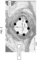
- the stent-electrode chronic intravascular stimulators may comprise multiple electrode contacts per anode and cathode.
- FIG 2 six electrode contacts per anode and cathode are shown, but the number of contacts can vary between 4 and 12 depending of the target vessel size.
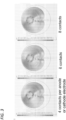
- Figure 3 shows alternative embodiments where 4, 6 and 8 electrodes are used.
- 4, 6, 8, 10 or 12 electrode contacts per anode and cathode are used, but 5, 7, 9 or 11 electrode contacts per anode and cathode may be used instead. It is possible for different numbers of electrode contacts to be used for the anode and the cathode, but it is preferred to use the same number for both the anode and the cathode.
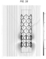
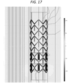
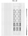
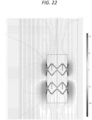
- Figures 16 to 21 are examples of an asymmetric configuration wherein one of the sets of electrode contacts (in this case the anode, with blue indication corresponding to the more negative of the two values indicated on the accompanying measurement scale) is closer to one end of the scaffold and sleeve of insulating material than the other of the sets (in this case the cathode, with red indication corresponding to the more positive of the two values indicated on the accompanying measurement scale) is to the other end.
- Symmetric and asymmetric embodiments may also exist with a unitary body.
- the symmetric scaffolding configuration described above may exist as an asymmetric embodiment, and the asymmetric scaffolding configuration described above may exist as a symmetric embodiment.
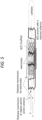
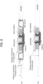
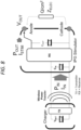
- Figures 4 to 8 show an embodiment of a split-stent-electrode chronic intravascular stimulator comprising a miniature implantable pulse generator (IPG) with wireless antenna for receiving power and communication from a transmitter (described elsewhere herein).
- Figures 4 to 8 show a split-stent, though the embodiment would be just as applicable to a non-conductive type.
- IPG implantable pulse generator
- the embodiments comprises two scaffold structures each including contact electrode(s) as described elsewhere herein.
- One scaffold structure provides an anode and the other provides a cathode.
- Each contact electrode is coupled to a miniature IPG in any manner as described elsewhere herein.
- the energizer (and optionally its charger) may be a wearable device, or may be implanted in a subcutaneous pocket of a patient.
- a wearable device may be advantageous for ad-hoc stimulation and/or where the charger requires frequent recharging.
- an implantable device may be advantageous to deliver continuous stimulation, or deliver a scheduled therapy on a program, wherein the powering modality between the implanted charger and the IPG stimulator can be near-field, mid-field or ultrasound.
- Figure 10 shows an alternative energy transfer schedule applicable to the system of figures 7 and 8 .
- energy supplied from a wireless charger is stored in capacitors until the charge required to deliver a micro-burst is accumulated.
- this is the charge required to deliver an 'active period' dose comprising of a burst of pulses in one active period.
- the required charge is accumulated, it is used to apply therapy.
- this system requires smaller capacitors, and less time to accumulate the charge for stimulation.
- the system requires slightly higher input energy to charge the capacitor or other storage elements to the desired output voltage level. Moreover, it requires energy supplied continuously through the duration of the therapy.
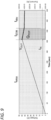
- Figure 11 shows eCAP amplitude (in percentage of first responses) over number N of pulses for different signal parameters, specifically 1Hz, 10Hz, 30Hz continuous, and a burst pattern of 10Hz comprising 5 pulses every 5 seconds.
- preferred parameters of stent-electrode stimulation systems described elsewhere herein are 10Hz pulses with 0.5sec ON time and 5sec OFF time at current amplitudes ranging from 10mA to 40mA and pulse widths ranging from 1ms to 4ms, for a total duration of 60sec up to 300sec.
- preferred parameters of stent-electrode stimulation systems described elsewhere herein are 1Hz pulses delivered continuously at current amplitudes ranging from 10mA to 40mA and pulse widths ranging from 1ms to 4ms, for a total duration of 60sec up to 300sec. This will achieve the same therapeutic effect as 10Hz, 0.5sec/5sec ON/OFF parameters but with less peak input energy demands.
- the CP connects to the charger via BLE to program therapy parameters in non-volatile memory. Therapy parameters may also be programmed into the stent IPG non-volatile memory.
- the CP & PR are used to monitor therapy by communicatively coupling with the charger while the charger energizes the IPG stent implant to deliver therapy.
- the charger energizes the stent-IPG through wireless powering scheme based on 6.78MHz or 13.56MHz ISM bands, ultrasound or mid-field powering. It supports BLE with the CP/PR and NFC with the stent IPG. It will be appreciated that other wireless powering schemes may be used, and other communication protocols may be used for communication.
- the stent-IPG stimulator is energized by the charger while therapy is being delivered. It may also link to external devices such as the charger and CP/PR over the NFC protocol.
- the stent-IPG is a single-fault safe device since it does not contain a battery and is not intended to be explanted in the event of failure.
- the charger of the system of figure 12A energizes the stent-IPG stimulator via NFC to deliver therapy and links to the CP/PR via BLE.
- the CP/PR of figure 12 provides patient app gateway to the cloud in order to download/upload therapy parameters, track compliance and sends reminders.
- the CP/PR also links to the charger via BLE to monitor progress during therapy and links to the stent-IPG stimulator via NFC for diagnostics and monitoring.
- the stent-IPG stimulator is energized by charger while therapy is delivered and links to Charger or CP/PR via NFC. It is a single-fault safe device, by which it is meant that it does not comprise a battery.
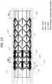
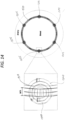
- each substantially annular portion of the stent-electrode 1300 is equally spaced circumferentially around the perimeter of each substantially annular portion of the stent-electrode 1300, though more or fewer electrodes can be provided, and the spacing can be adjusted depending on the particular application.
- two substantially annular portions 1308a, 1308b are provided, resulting in a total of twelve electrodes.
- the stent-electrode 1300 of figures 13 and 14 has features and concepts in common with the devices described above in connection with figures 1 to 12 .
- the stent-electrode 1300 of figures 13 and 14 is provided with hooks or projections 1310 that, in the illustrated embodiment, extend from the or each substantially annular portion 1308 of the scaffold 1320, and extend along the longitudinal axis of the stent.
- These hooks or projections 1310 can be any suitable shape, and are for the purpose of attaching or forming the electrodes 1305.
- each hook or projection 1310 of the relevant substantially annular portion 1308a, 1308b carries a respective electrode 1305, though it is not necessary for every hook or projection 1310 of the scaffold 1320 to carry an electrode.
- the stent of this application could be used in conjunction with any suitable blood vessel in order to apply an electrical signal to any corresponding nerve.
- Other examples include: the carotid artery and the vagus nerve and the cervical sympathetic ganglion; the aorta and the phrenic nerve, the vagus nerve, the superior mesenteric ganglion, and the inferior mesenteric ganglion; the renal artery and the renal nerves; and the subclavian artery and the brachial plexus; and common hepatic artery and its associated nerves; and gastroduodenal artery and its associated nerves; iliac artery and splanchnic nerves.
- the invention may be useful for treating subjects who are suffering from, or who are at risk of developing, diseases, disorders or conditions associated with inflammation, e.g. inflammatory disorders, e.g., autoimmune disorders.
- the invention may treat or ameliorate the effects of such diseases, disorders or conditions by reducing inflammation. This may be achieved by decreasing the production and release of pro-inflammatory cytokines, and/or by increasing the production and release of anti-inflammatory cytokines and pro-resolving molecules, from the spleen, by electrically stimulating the splenic arterial nerve as described herein.
- systemic or local inflammatory diseases and conditions such as asthma, allergy, anaphylactic shock, immune complex disease, sepsis, septicemia, endotoxic shock, eosinophilic granuloma, granulomatosis, organ ischemia, reperfusion injury, organ necrosis, hay fever, cachexia, hyperexia, septic abortion, HIV infection, herpes infection, organ transplant rejection, disseminated bacteremia, Dengue fever, malaria and sarcoidosis.
- systemic or local inflammatory diseases and conditions such as asthma, allergy, anaphylactic shock, immune complex disease, sepsis, septicemia, endotoxic shock, eosinophilic granuloma, granulomatosis, organ ischemia, reperfusion injury, organ necrosis, hay fever, cachexia, hyperexia, septic abortion, HIV infection, herpes infection, organ transplant rejection, disseminated bacteremia, Dengue fever, malaria and sarcoidosis.
- Inflammatory disorders also include conditions associated with immune or inflammatory response (i.e. acute inflammatory episodes) include injury to nerves or other tissue and pain associated with nerve or other tissue. Injury may be due to a physical, chemical or mechanical trauma.
- Non- limiting examples of injury include acute trauma, burn, whiplash, musculoskeletal strains, and post-operative surgery complications, such as DVT, cardiac dysrhythmia, ventilator associated lung injury, and post-operative ileus.
- Stimulation of the splenic arterial nerve may result in: (a) a decrease in the level of a pro-inflammatory cytokine in the plasma or serum by ⁇ 5%, ⁇ 10%, ⁇ 15%, ⁇ 20%, ⁇ 25%, ⁇ 30%, ⁇ 35%, ⁇ 40%, ⁇ 45%, ⁇ 50%, ⁇ 60%, ⁇ 70%, ⁇ 80%, ⁇ 90%, or ⁇ 95%; and/or (b) an increase in the level of an anti-inflammatory cytokine in the plasma or serum by ⁇ 5%, ⁇ 10%, ⁇ 15%, ⁇ 20%, ⁇ 25%, ⁇ 30%, ⁇ 35%, ⁇ 40%, ⁇ 45%, ⁇ 50%, ⁇ 60%, ⁇ 70%, ⁇ 80%, ⁇ 90%, ⁇ 95%, ⁇ 100%, ⁇ 150% or ⁇ 200%.
- the level in the serum is measured.
- the level of catecholamine e.g. norepinephrine or epinephrine
- the level of catecholamine may increase, for example, by: ⁇ 5%, ⁇ 10%, ⁇ 15%, ⁇ 20%, ⁇ 25%, ⁇ 30%, ⁇ 35%, ⁇ 40%, ⁇ 45%, ⁇ 50%, ⁇ 60%, ⁇ 70%, ⁇ 80%, ⁇ 90%, ⁇ 95%, ⁇ 100%, ⁇ 150% or ⁇ 200%.
- Pro-inflammatory cytokines are known in the art. Examples of these include tumor necrosis factor (TNF; also known as TNF ⁇ or cachectin), interleukin (IL)-1 ⁇ , IL-1 ⁇ , IL-2; IL-5, IL-6, IL-8, IL-15, IL 18, interferon ⁇ (IFN- ⁇ ); platelet-activating factor (PAF), thromboxane; soluble adhesion molecules; vasoactive neuropeptides; phospholipase A2; plasminogen activator inhibitor (PAI-1); free radical generation; neopterin; CD14; prostacyclin; neutrophil elastase; protein kinase; monocyte chemotactic proteins 1 and 2 (MCP-1, MCP-2); macrophage migration inhibitory factor (MIF), high mobility group box protein 1 (HMGB-1), and other known factors.
- TNF tumor necrosis factor
- IL-1 ⁇ interleukin-1 ⁇
- IL-2 interleukin
- cytokines may act as anti-inflammatory cytokines in certain circumstances, and vice-versa.
- cytokines are typically referred to as pleiotropic cytokines.
- the invention may be useful for increasing an immune response in a subject.
- increasing an immune response or a pro-inflammatory response may be beneficial in a subject who is immunocompromised and thus in need of increasing pro-inflammatory cytokines for inducing beneficial pro-inflammatory responses.
- This may be particularly beneficial in immunocompromised subjects who are particularly vulnerable to infections.
- immunocompromised subjects in which this embodiment of the invention may be useful include, but are not limited to, subjects undergoing chemotherapy, subjects with HIV or AIDS, subjects taking a course of steroids, and subjects with immunosenescence, for example, subjects with age-associated immunodeficiency.
- the invention may be used to increase a pro-inflammatory response in a subject wherein that subject is undergoing or is about to undergo a therapy in which immunocompromisation is an undesired side effect of that therapy.
- the invention is useful for inducing a pro-inflammatory response to boost the acquisition of resistance provided by a vaccine.
- the neurostimulation device of the invention may be used in a method of vaccination, e.g. to boost the efficacy of a vaccine.
- Factors involved in the inflammatory cascade may also be useful measurable parameters in the context of the invention.
- the signal transduction cascades include factors such as NF ⁇ -B, Egr-1, Smads, toll-like receptors, and MAP kinases.
- cytokine, chemokine, or a catecholamine may be directly detected, e.g. by ELISA.
- the presence or amount of a nucleic acid, such as a polyribonucleotide, encoding a polypeptide described herein may serve as a measure of the presence or amount of the polypeptide.
- detecting the presence or amount of a polypeptide will include detecting the presence or amount of a polynucleotide encoding the polypeptide.
- Quantitative changes of the biological molecules can be measured in a living body sample such as urine or plasma. Detection of the biological molecules may be performed directly on a sample taken from a subject, or the sample may be treated between being taken from a subject and being analyzed.
- a blood sample may be treated by adding anti-coagulants (e.g. EDTA), followed by removing cells and cellular debris, leaving plasma containing the relevant molecules (e.g. cytokines) for analysis.
- a blood sample may be allowed to coagulate, followed by removing cells and various clotting factors, leaving serum containing the relevant molecules (e.g. cytokines) for analysis.
- the invention may involve determining the subject's circadian rhythm phase markers, such as the level of cortisol (or its metabolites thereof), the level of melatonin (or its metabolites thereof) or core body temperature.
- Cortisol or melatonin levels can be measured in the blood (e.g. plasma or serum), saliva or urine. Methods of determining the levels of these markers are known in the art, e.g. by enzyme-linked immunosorbent assay (ELISA) or radioimmunoassay.
- rhythm phase markers indicate circadian oscillations of inflammatory markers which may beneficially be regulated by application of a signal with a neurostimulation device or system of the invention, then application of the signal at night at a suitable periodicity according to the subject's circadian rhythm may be appropriate.
- the baseline for any neural activity in a subject need not be a fixed or specific value, but rather can fluctuate within a normal range or may be an average value with associated error and confidence intervals. Suitable methods for determining baseline values are well known to the skilled person.
- the physiological parameter is an action potential or pattern of action potentials in a nerve of the subject, wherein the action potential or pattern of action potentials is associated with the disease, disorder or condition to be treated.
- a predefined threshold value for a physiological parameter is defined elsewhere herein.
- a subject of the invention may, in addition to being treated with a neurostimulation device or system according to the invention, receive medicine for their disease, disorder or condition, as discussed elsewhere herein.
- anticoagulant therapy e.g. with heparin
- the neurostimulation device applies an electrical signal via at least one electrode which is placed in proximity to, i.e. in a signalling relationship with, a splenic arterial nerve when the distal end of the catheter or stent of the neurostimulation device is inserted into a blood vessel, for example a splenic artery.
- the electrode may be said to be placed in signalling contact with the splenic arterial nerve.
- signalling contact is where at least part of the electrical signal applied via the at least one electrode is received at the nerve.
- Non-destructive signal is a signal that, when applied, does not irreversibly damage the underlying neural signal conduction ability of the nerve. That is, application of a non-destructive signal maintains the ability of the nerve or fibers thereof, or other nerve tissue to which the signal is applied, to conduct action potentials when application of the signal ceases, even if that conduction is in practice artificially stimulated as a result of application of the non-destructive signal.
- Electrical signals applied according to the invention may be a voltage or a current waveform (e.g. constant voltage or a constant current waveform).
- the electrical signal may be characterized by one or more electrical signal parameters.
- the electrical signal parameters include waveform, frequency, and amplitude.
- the electrical signal may be characterized by the pattern of application of the electrical signal to the nerve.
- the pattern of application refers to the timing of the application of the electrical signal to the nerve.
- the pattern of application may be continuous application or periodic application.
- Periodic application refers to where the electrical signal is applied to the nerve in a repeating pattern (e.g. an on-off pattern).
- a pulse train comprises a plurality of sequential pulses, where each pulse may be characterized by pulse width, pulse height and/or interphase delay.
- Pulse width refers to a width (or time duration) of a primary phase of the waveform.
- the pulse width refers to a width (or duration) of the first phase.
- a pulse duration refers to the time duration during which the pulse is applied or delivered for. This may also be referred to as a stimulation time.
- the inclusion of an interphase delay may reduce the threshold of pulse height required to stimulate neural activity in a human splenic nerve. Therefore, in some examples, the pulse train may have an interphase delay.
- the pulses may be biphasic in nature.
- the term "biphasic" refers to a pulse which applies to the nerve over time both a positive and negative charge (anodic and cathodic phases).
- the pulse width includes the time duration of a primary phase of the waveform, for example the anodic phase or the cathodic phase.
- the primary phase may also be referred to herein as the stimulation phase.
- the biphasic pulse is asymmetric, but remains charged balanced, then the areas of the opposing phases must equal. Amplitude (see below) can be reduced, but the pulse width would need to be extended to ensure the area under the curve is matched.
- the electrical signal applied to the nerve would be within clinical safety margins (e.g. suitable for maintaining nerve signaling function, suitable for maintaining nerve integrity, and suitable for maintaining the safety of the subject).
- the table below demonstrates example electrical signal parameters for each corresponding recruitment level of human splenic nerve using computational models. These are example values only, where a different current amplitude or pulse width may be used depending on the electrode surface area or electrode configuration of a device to achieve a corresponding charge density. In the examples given below, the electrode area is assumed to be 0.067cm 2 . A range around the example values provided may also be used.
- Periodic application refers to where the electrical signal is applied to the nerve in a repeating pattern.
- the preferred repeating pattern is an on-off pattern, where the signal is applied in a sequence of pulse trains for a first duration, referred to herein as an 'on' duration, then stopped for a second duration, referred to herein as an 'off' duration, then applied again for the first duration, then stopped again for the second duration, etc.
- the periodic on-off pattern may have an on duration of between 0.1 and 10 s and an off duration of between 0.5 and 30 s.
- the on duration may be ⁇ 0.2 s, ⁇ 0.5 s, ⁇ 1 s, ⁇ 2 s, ⁇ 5 s, or ⁇ 10 s.
- the on duration may be ⁇ 0.1 s, ⁇ 0.2 s, ⁇ 0.5 s, ⁇ 1 s, ⁇ 2 s, or ⁇ 5 s. Any combination of the upper and lower limits above for the on duration is also possible.
- the off duration may be ⁇ 1 s, ⁇ 3 s, ⁇ 5 s, ⁇ 10 s, ⁇ 15 s, ⁇ 20 s, ⁇ 25 s, or ⁇ 30 s.
- the off duration may be ⁇ 0.5 s , ⁇ 1 s, ⁇ 2 s, ⁇ 5 s, ⁇ 10 s, ⁇ 15 s, ⁇ 20 s, or ⁇ 25 s. Any combination of the upper and lower limits above for the off duration is also possible.
- the periodic on-off pattern has an on duration of 0.5 s on, and an off duration of 4.5 sec off.
- Periodic application may also be referred to as a duty cycled application.
- a duty cycle represents the percentage of time that the signal is applied to the nerve for a cycle of the periodic pattern.
- a duty cycle of 20% may represent a periodic pattern having an on duration of 2 s, and an off duration of 10 s.
- a duty cycle of 20% may represent a periodic pattern having a on duration of 1 s, and an off duration of 5 s.
- Duty cycles suitable for the present invention are between 0.1% and 100%.
- the duty cycle may be 10%.
- Episodic application refers to where the electrical signal is applied to the nerve for a discrete number of episodes throughout a day.
- the electrical signal according to the invention may be applied for up to a maximum of twenty six episodes per day.
- the number of episodes of signal application per day may be one, two, three, four, five, six, seven, eight, nine, ten, eleven, twelve or another number up to twenty six.
- the electrical signal may be applied episodically every 2 to 3 hours.
- the electrical signal may be applied episodically once every 2 hours, 2 hour 15 min, 2 hour 30 min, 2 hour 45 min, or 3 hours.
- Each episode may be defined by a set duration or a set number of iterations of the electrical signal.
- each episode comprises applying to the nerve between 10 and 2400 pulses of the electrical signal, optionally between 100 and 2400 pulses of the electrical signal, further optionally between 50 and 2400 pulses, e.g. between 200 and 1200 pulses of the electrical signal, between 400 and 600 pulses of the electrical signal, etc.
- each episode may comprise applying ⁇ 10, ⁇ 50, ⁇ 60, ⁇ 100, ⁇ 400, ⁇ 600, ⁇ 800, ⁇ 1200, ⁇ 1600, ⁇ 2000, or ⁇ 2400 pulses of the electrical signal.
- each episode may comprise applying ⁇ 200, ⁇ 400, ⁇ 600, ⁇ 800, ⁇ 1000, or ⁇ 1200 pulses of the electrical signal.
- each episode may comprise applying ⁇ 400, ⁇ 425, ⁇ 450, ⁇ 475, ⁇ 500, ⁇ 525, ⁇ 550, ⁇ 575, or ⁇ 600 pulses of the electrical signal.
- each episode comprises between 20 and 40 iterations of the periodic pattern.
- each episode comprises applying 20, 25, 30, 35, or 40 iterations of the periodic pattern, or any number therebetween. The higher the frequency, the lower the number of iterations.
- the episodes may be based on the subject's sleep-wake cycle, in particular the episodes may be whilst the subject is asleep. In some such embodiments, the episodes may be applied between 10 pm and 6 am. This may also be incluenced by the surgery times.
- the sleep-wake cycle may be measured via known methods by detecting the subject's circadian rhythm phase markers (e.g. cortisol level, melatonin level or core body temperature), and/or a detector for detecting the subject's movements.
- the inventors have found preferred frequencies for stimulating a splenic arterial nerve when using the device of the invention.
- the inventors have found preferred frequencies for embodiments where the electrical signal is applied periodically and for embodiments where the electrical signal is applied continuously.
- the electrical signal has a frequency of ⁇ 300 Hz, preferably ⁇ 50 Hz, more preferably ⁇ 10 Hz.
- the frequency of the electrical signal may be ⁇ 50 Hz, ⁇ 100 Hz, ⁇ 150 Hz, ⁇ 200 Hz, ⁇ 250 Hz or ⁇ 300 Hz.
- the frequency of the electrical signal may be ⁇ 10 Hz, ⁇ 15 Hz, ⁇ 20 Hz, ⁇ 25 Hz, ⁇ 30 Hz, ⁇ 35 Hz, ⁇ 40 Hz, ⁇ 45 Hz, or ⁇ 50 Hz.
- the frequency may be ⁇ 1 Hz, ⁇ 2 Hz, ⁇ 5 Hz, or ⁇ 10 Hz.
- the frequency of the electrical signal may be ⁇ 10 Hz, ⁇ 15 Hz, ⁇ 20 Hz, ⁇ 25 Hz, ⁇ 30 Hz, ⁇ 35 Hz ⁇ 40 Hz, ⁇ 45 Hz, or ⁇ 50 Hz.
- the frequency of the electrical signal may be ⁇ 0.1 Hz, ⁇ 0.2 Hz, ⁇ 0.5 Hz, ⁇ 1 Hz, ⁇ 2 Hz, or ⁇ 5 Hz. Any combination of the upper and lower limits above is also possible.
- the electrical signal has a frequency of ⁇ 50 Hz, preferably ⁇ 10 Hz, more preferably ⁇ 2 Hz, even more preferably ⁇ 1 Hz.
- the frequency may be ⁇ 1 Hz, ⁇ 2 Hz, ⁇ 5 Hz, or ⁇ 10 Hz.
- the frequency may be ⁇ 0.1 Hz, ⁇ 0.2 Hz, ⁇ 0.3 Hz, ⁇ 0.4 Hz ⁇ 0.5 Hz, ⁇ 0.6 Hz ⁇ 0.7 Hz, ⁇ 0.8 Hz, or ⁇ 0.9 Hz.
- the pulses are applied to the nerve at intervals according to the above-mentioned frequencies. For example, a frequency of 50 Hz results in 50 pulses being applied to the nerve per second.
Landscapes
- Health & Medical Sciences (AREA)
- Engineering & Computer Science (AREA)
- Biomedical Technology (AREA)
- Nuclear Medicine, Radiotherapy & Molecular Imaging (AREA)
- Radiology & Medical Imaging (AREA)
- Life Sciences & Earth Sciences (AREA)
- Animal Behavior & Ethology (AREA)
- General Health & Medical Sciences (AREA)
- Public Health (AREA)
- Veterinary Medicine (AREA)
- Cardiology (AREA)
- Heart & Thoracic Surgery (AREA)
- Computer Networks & Wireless Communication (AREA)
- Power Engineering (AREA)
- Vascular Medicine (AREA)
- Neurology (AREA)
- Neurosurgery (AREA)
- Orthopedic Medicine & Surgery (AREA)
- Electrotherapy Devices (AREA)
Applications Claiming Priority (3)
| Application Number | Priority Date | Filing Date | Title |
|---|---|---|---|
| US201962948593P | 2019-12-16 | 2019-12-16 | |
| EP20838159.0A EP4076624A1 (de) | 2019-12-16 | 2020-12-15 | Intravaskulärer neuromodulator mit stent-elektrode und zugehörige verfahren zur aktivierung eines nervs |
| PCT/GB2020/053223 WO2021123757A1 (en) | 2019-12-16 | 2020-12-15 | Stent-electrode intravascular neuromodulator and associated methods for activation of a nerve |
Related Parent Applications (1)
| Application Number | Title | Priority Date | Filing Date |
|---|---|---|---|
| EP20838159.0A Division EP4076624A1 (de) | 2019-12-16 | 2020-12-15 | Intravaskulärer neuromodulator mit stent-elektrode und zugehörige verfahren zur aktivierung eines nervs |
Publications (2)
| Publication Number | Publication Date |
|---|---|
| EP4578490A2 true EP4578490A2 (de) | 2025-07-02 |
| EP4578490A3 EP4578490A3 (de) | 2025-07-30 |
Family
ID=74130256
Family Applications (2)
| Application Number | Title | Priority Date | Filing Date |
|---|---|---|---|
| EP20838159.0A Pending EP4076624A1 (de) | 2019-12-16 | 2020-12-15 | Intravaskulärer neuromodulator mit stent-elektrode und zugehörige verfahren zur aktivierung eines nervs |
| EP25176189.6A Pending EP4578490A3 (de) | 2019-12-16 | 2020-12-15 | Intravaskulärer neuromodulator mit stentelektrode |
Family Applications Before (1)
| Application Number | Title | Priority Date | Filing Date |
|---|---|---|---|
| EP20838159.0A Pending EP4076624A1 (de) | 2019-12-16 | 2020-12-15 | Intravaskulärer neuromodulator mit stent-elektrode und zugehörige verfahren zur aktivierung eines nervs |
Country Status (3)
| Country | Link |
|---|---|
| US (1) | US20230010306A1 (de) |
| EP (2) | EP4076624A1 (de) |
| WO (1) | WO2021123757A1 (de) |
Families Citing this family (3)
| Publication number | Priority date | Publication date | Assignee | Title |
|---|---|---|---|---|
| WO2020142613A1 (en) | 2019-01-04 | 2020-07-09 | Shifamed Holdings, Llc | Internal recharging systems and methods of use |
| WO2021217059A1 (en) | 2020-04-23 | 2021-10-28 | Shifamed Holdings, Llc | Power management for interatrial shunts and associated systems and methods |
| WO2022269278A1 (en) * | 2021-06-23 | 2022-12-29 | Galvani Bioelectronics Limited | A stent-electrode intravascular neuromodulator and associated methods for activation of a nerve |
Family Cites Families (11)
| Publication number | Priority date | Publication date | Assignee | Title |
|---|---|---|---|---|
| US20080167699A1 (en) * | 2000-09-27 | 2008-07-10 | Cvrx, Inc. | Method and Apparatus for Providing Complex Tissue Stimulation Parameters |
| US8140170B2 (en) * | 2005-09-12 | 2012-03-20 | The Cleveland Clinic Foundation | Method and apparatus for renal neuromodulation |
| US20080039904A1 (en) * | 2006-08-08 | 2008-02-14 | Cherik Bulkes | Intravascular implant system |
| US8923970B2 (en) * | 2008-12-09 | 2014-12-30 | Nephera Ltd. | Stimulation of the urinary system |
| AU2013337780B2 (en) * | 2012-10-31 | 2018-04-05 | The Board Of Trustees Of The Leland Stanford Junior University | Wireless implantable sensing devices |
| US10779965B2 (en) * | 2013-11-06 | 2020-09-22 | Enopace Biomedical Ltd. | Posts with compliant junctions |
| US20160000590A1 (en) * | 2014-04-07 | 2016-01-07 | Washington University | Intravascular Device |
| EP3454937A1 (de) * | 2016-05-10 | 2019-03-20 | Cardiac Pacemakers, Inc. | Implantierbare medizinische vorrichtung für den vaskulären einsatz |
| EP3338853A1 (de) * | 2016-12-23 | 2018-06-27 | Sanofi-Aventis Deutschland GmbH | Medikamentenverabreichungsvorrichtung |
| KR102118837B1 (ko) * | 2017-07-31 | 2020-06-03 | 엑스케이스 인코포레이티드 | 편조 구조물을 가진 조향가능한 의료 디바이스 및 그 제조 방법 |
| KR102857889B1 (ko) * | 2018-05-30 | 2025-09-09 | 파운드리 이노베이션 앤드 리서치 1 리미티드 | 무선 공진 회로와 가변 인덕턴스 혈관 모니터링 이식체와 그를 위한 정착 구조 |
-
2020
- 2020-12-15 US US17/785,374 patent/US20230010306A1/en active Pending
- 2020-12-15 EP EP20838159.0A patent/EP4076624A1/de active Pending
- 2020-12-15 EP EP25176189.6A patent/EP4578490A3/de active Pending
- 2020-12-15 WO PCT/GB2020/053223 patent/WO2021123757A1/en not_active Ceased
Also Published As
| Publication number | Publication date |
|---|---|
| WO2021123757A1 (en) | 2021-06-24 |
| EP4076624A1 (de) | 2022-10-26 |
| EP4578490A3 (de) | 2025-07-30 |
| US20230010306A1 (en) | 2023-01-12 |
Similar Documents
| Publication | Publication Date | Title |
|---|---|---|
| US11259732B2 (en) | Method and device for acquiring physiological data during tissue stimulation procedure | |
| AU2017254363B2 (en) | Pulse generator system for promoting desynchronized firing of recruited neural populations | |
| EP1981584B1 (de) | Intravaskuläre vorrichtung zur neuromodulation | |
| EP4578490A2 (de) | Intravaskulärer neuromodulator mit stentelektrode | |
| US8527064B2 (en) | System for stimulating autonomic targets from pulmonary artery | |
| JP6400028B2 (ja) | 複合パルス列を生成するために柔軟性の増大した神経刺激システム | |
| US20070106357A1 (en) | Intravascular Electronics Carrier Electrode for a Transvascular Tissue Stimulation System | |
| US20030216789A1 (en) | Method and system for treating sleep apnea | |
| EP2766086A2 (de) | System und verfahren zur neuromodulation | |
| US20160331975A1 (en) | Active implantable medical device with automatic optimization of the configuration of a multi-electrode stimulation lead | |
| JP2010532700A (ja) | 埋込み可能な医療デバイスのためのテレメトリ聴取ウィンドウ管理 | |
| US20220387785A1 (en) | Stimulation systems with user-specified routines and methods of making and using | |
| JP2018537236A (ja) | 医療装置システムにおける伝導通信 | |
| US20240299737A1 (en) | A stent-electrode intravascular neuromodulator and associated methods for activation of a nerve | |
| EP3727563A1 (de) | Nervenstimulationsvorrichtung zur unidirektionalen stimulation und stromsteuerung | |
| WO2020254794A1 (en) | System for the treatment of disorders associated with inflammation | |
| JP2013529508A (ja) | 除細動から患者の不快感を低減するためのパルスパラメータおよび電極構成 | |
| US12447343B2 (en) | Neurostimulation device for blocking blood flow between electrodes | |
| US12434063B2 (en) | Leadfree multi-site bioelectronic stimulator system | |
| WO2020260859A1 (en) | Neurostimulation device for blocking blood flow between electrodes |
Legal Events
| Date | Code | Title | Description |
|---|---|---|---|
| PUAI | Public reference made under article 153(3) epc to a published international application that has entered the european phase |
Free format text: ORIGINAL CODE: 0009012 |
|
| STAA | Information on the status of an ep patent application or granted ep patent |
Free format text: STATUS: THE APPLICATION HAS BEEN PUBLISHED |
|
| REG | Reference to a national code |
Ref country code: DE Ref legal event code: R079 Free format text: PREVIOUS MAIN CLASS: A61N0001378000 Ipc: A61N0001050000 |
|
| PUAL | Search report despatched |
Free format text: ORIGINAL CODE: 0009013 |
|
| AC | Divisional application: reference to earlier application |
Ref document number: 4076624 Country of ref document: EP Kind code of ref document: P |
|
| AK | Designated contracting states |
Kind code of ref document: A2 Designated state(s): AL AT BE BG CH CY CZ DE DK EE ES FI FR GB GR HR HU IE IS IT LI LT LU LV MC MK MT NL NO PL PT RO RS SE SI SK SM TR |
|
| AK | Designated contracting states |
Kind code of ref document: A3 Designated state(s): AL AT BE BG CH CY CZ DE DK EE ES FI FR GB GR HR HU IE IS IT LI LT LU LV MC MK MT NL NO PL PT RO RS SE SI SK SM TR |
|
| RIC1 | Information provided on ipc code assigned before grant |
Ipc: A61N 1/05 20060101AFI20250625BHEP Ipc: A61N 1/372 20060101ALI20250625BHEP Ipc: A61N 1/375 20060101ALI20250625BHEP Ipc: A61N 1/378 20060101ALI20250625BHEP |