EP4578368A1 - A dishwasher comprising a mounting member - Google Patents
A dishwasher comprising a mounting member Download PDFInfo
- Publication number
- EP4578368A1 EP4578368A1 EP24208668.4A EP24208668A EP4578368A1 EP 4578368 A1 EP4578368 A1 EP 4578368A1 EP 24208668 A EP24208668 A EP 24208668A EP 4578368 A1 EP4578368 A1 EP 4578368A1
- Authority
- EP
- European Patent Office
- Prior art keywords
- washing tub
- dishwasher
- rail
- hole
- mounting member
- Prior art date
- Legal status (The legal status is an assumption and is not a legal conclusion. Google has not performed a legal analysis and makes no representation as to the accuracy of the status listed.)
- Pending
Links
Images


Classifications
-
- A—HUMAN NECESSITIES
- A47—FURNITURE; DOMESTIC ARTICLES OR APPLIANCES; COFFEE MILLS; SPICE MILLS; SUCTION CLEANERS IN GENERAL
- A47L—DOMESTIC WASHING OR CLEANING; SUCTION CLEANERS IN GENERAL
- A47L15/00—Washing or rinsing machines for crockery or tableware
- A47L15/42—Details
- A47L15/50—Racks ; Baskets
- A47L15/507—Arrangements for extracting racks, e.g. roller supports
Definitions
- the present invention relates to a dishwasher comprising a mounting member.
- the washing tubs are usually manufactured from metal. The placement is performed by means of the racks in the washing tub.
- the racks are generally detachably attached to the washing tub. There are various methods for attaching the racks into the washing tub.
- the rack rails are placed on the wheels on the washing tub wall so as to enable the rack to move forward and backward.
- the racks are attached to a rail and the rails are fixed to the washing tub wall since it facilitates the movement of the rack and it is safer.
- the use of telescopic rails is also common due to ease of use. While the rails are being mounted to the washing tub wall, a screw is passed through the washing tub wall and screwed from behind by an operator. However, during the assembly, the operator must hold the rail from inside the washing tub and screw the same from outside. This causes difficulty in the assembly and even causes the rails to be mounted in a crooked manner or deformed.
- a dishwasher comprising a mounting member which enables the rails to be mounted to the washing tub.
- the aim of the present invention is the realization of a dishwasher comprising rails with facilitated mounting.
- the dishwasher realized in order to attain the aim of the present invention, explicated in the first claim and the respective claims thereof, comprises a body; a washing tub which is disposed in the body and wherein the washing process is performed; at least one rail which is mounted to the washing tub walls; at least one rack which is attached to the rails; at least one mounting member which enables the rail to be mounted to the washing tub wall; and a hole which is provided on the washing tub wall and through which the mounting member passes.
- the mounting member is a threaded screw screwed through the rail. By passing the screw through the hole, the rail is mounted to the washing tub wall.
- the dishwasher of the present invention comprises a holding member having at least one counter hole which is positioned on the back of the washing tub so as to align with the hole while the rail is being mounted on the washing tub and a clamping member located on the counter hole.
- the dishwasher comprises the clamping member which can be gradually expanded to compress the mounting member.
- a clamping member and a holding member compatible with different mounting members are provided.
- the dishwasher comprises the clamping member which can be attached to and detached from on the holding member.
- the clamping member can be mounted by being adhered or attached onto the holding member.
- the clamping member is enabled to be attached onto the currently used plates. Double-sided tape can be also preferred to attach the clamping member.
- the rack (5) can be attached by means of a pair of rails (4) located opposite each other in the washing tub (3).
- the rails (4) are fixed to the wall of the washing tub (3) by passing the mounting members (6) thereon through the hole (7) provided on the washing tub (3).
- the dishwasher (1) comprises the clamping member (9) which can be attached to and detached from the holding member (10).
- the clamping member (9) can be mounted by being adhered or attached onto the holding member (10).
- the clamping member (9) is enabled to be attached onto the currently used plates.
- Double-sided tape can be also preferred to attach the clamping member (9).
Landscapes
- Washing And Drying Of Tableware (AREA)
Abstract
The present invention relates to a dishwasher (1) comprising a body (2); a washing tub (3) which is disposed in the body (2) and wherein the washing process is performed; at least one rail (4) which is mounted on the walls of the washing tub (3); at least one rack (5) which is supported by at least two rails (4) opposite each other and whereon the kitchen items are placed; at least one mounting member (6) which has threads thereon and which extends from the rail (4) towards the washing tub (3) when the rail (4) is mounted on the wall of the washing tub (3); and at least one hole (7) which is provided on the side wall of the washing tub (3) and through which the mounting member (6) passes.
Description
- The present invention relates to a dishwasher comprising a mounting member.
- In dishwashers, the kitchen items are placed into the washing tub to be cleaned. The washing tubs are usually manufactured from metal. The placement is performed by means of the racks in the washing tub. The racks are generally detachably attached to the washing tub. There are various methods for attaching the racks into the washing tub. Usually, the rack rails are placed on the wheels on the washing tub wall so as to enable the rack to move forward and backward. However, the racks are attached to a rail and the rails are fixed to the washing tub wall since it facilitates the movement of the rack and it is safer. Moreover, the use of telescopic rails is also common due to ease of use. While the rails are being mounted to the washing tub wall, a screw is passed through the washing tub wall and screwed from behind by an operator. However, during the assembly, the operator must hold the rail from inside the washing tub and screw the same from outside. This causes difficulty in the assembly and even causes the rails to be mounted in a crooked manner or deformed.
- In the state of the art Patent Document No.
EP3338614 , a dishwasher is disclosed, comprising a mounting member which enables the rails to be mounted to the washing tub. - The aim of the present invention is the realization of a dishwasher comprising rails with facilitated mounting.
- The dishwasher realized in order to attain the aim of the present invention, explicated in the first claim and the respective claims thereof, comprises a body; a washing tub which is disposed in the body and wherein the washing process is performed; at least one rail which is mounted to the washing tub walls; at least one rack which is attached to the rails; at least one mounting member which enables the rail to be mounted to the washing tub wall; and a hole which is provided on the washing tub wall and through which the mounting member passes. The mounting member is a threaded screw screwed through the rail. By passing the screw through the hole, the rail is mounted to the washing tub wall.
- The dishwasher of the present invention comprises a holding member having at least one counter hole which is positioned on the back of the washing tub so as to align with the hole while the rail is being mounted on the washing tub and a clamping member located on the counter hole. By means of the counter hole and the clamping member located in the counter hole arranged so as to align with the mounting member, namely the screw, when the same is passed through the hole and comes out of the back surface of the washing tub wall, the rail is enabled to be mounted without being held by the operator.
- In an embodiment of the present invention, the dishwasher comprises a plurality of flexible claws which are provided on the holding member. The flexible claws are positioned around the counter hole. The flexible claws have an angular and flexible form. Thus, the flexible claws engage with the threads of the mounting member so as to ensure fixing.
- In an embodiment of the present invention, the dishwasher comprises the clamping member having at least three flexible claws. By using at least three flexible claws, the mounting member passing through the center is fully held.
- In an embodiment of the present invention, the dishwasher comprises the holding member which is mounted from behind the washing tub wall as the mounting member passes through the hole. The holding member is fixed behind the washing tub wall by means of the flexible claws engaging with the mounting member.
- In an embodiment of the present invention, the dishwasher comprises the clamping member which can be gradually expanded to compress the mounting member. Thus, a clamping member and a holding member compatible with different mounting members are provided.
- In an embodiment of the present invention, the dishwasher comprises the clamping member which can be attached to and detached from on the holding member. The clamping member can be mounted by being adhered or attached onto the holding member. Thus, the clamping member is enabled to be attached onto the currently used plates. Double-sided tape can be also preferred to attach the clamping member.
- By means of the present invention, a dishwasher is realized, comprising the holding member which facilitates the mounting of the rails into the washing tub.
- The dishwasher realized in order to attain the aim of the present invention is illustrated in the attached figures, where:
-
Figure 1 - is the perspective view of the dishwasher. -
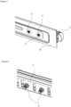
Figure 2 - is the perspective view of the rail and the holding member. -
Figure 3 - is the perspective view of the rail and the mounting member. -
Figure 4 - is the perspective view of the holding member and the clamping member. - The elements illustrated in the figures are numbered as follows:
- 1- Dishwasher
- 2- Body
- 3- Washing tub
- 4- Rail
- 5- Rack
- 6- Mounting member
- 7- Hole
- 8- Counter hole
- 9- Clamping member
- 10- Holding member
- 11- Flexible claw
- The dishwasher (1) comprises a body (2); a washing tub (3) which is disposed in the body (2) and wherein the washing process is performed; at least one rail (4) which is mounted on the walls of the washing tub (3); at least one rack (5) which is supported by at least two rails (4) opposite each other and whereon the kitchen items are placed; at least one mounting member (6) which has threads thereon and which extends from the rail (4) towards the washing tub (3) when the rail (4) is mounted on the wall of the washing tub (3); and at least one hole (7) which is provided on the side wall of the washing tub (3) and through which the mounting member (6) passes. The racks (5) whereon the kitchen items are placed are placed in the washing tub (3). The rack (5) can be attached by means of a pair of rails (4) located opposite each other in the washing tub (3). The rails (4) are fixed to the wall of the washing tub (3) by passing the mounting members (6) thereon through the hole (7) provided on the washing tub (3).
- The dishwasher (1) of the present invention comprises a holding member (10) having at least one counter hole (8) which is positioned on the back of the washing tub (3) wall so as to align with the hole (7) while the rail (4) is being mounted on the washing tub (3) wall and a clamping member (9) located on the counter hole (8). When the mounting member (6), preferably the screw, is passed through the hole (7), the holder member (10) is attached to the mounting member (6) from behind the wall of the washing tub (3) by means of the counter hole (8). The counter hole (8) comprises the clamping member (9) thereon which engages with the threads of the screw so as to enable the screw to be fixed on the washing tub (3) by tight fit. Thus, the need for the operator holding the rail (4) while mounting the same on the washing tub (3) is eliminated. The assembly process becomes easier and safer.
- In an embodiment of the present invention, the dishwasher (1) comprises the clamping member (9) which has a plurality of flexible claws (11) in an angular form provided on the holding member (10) and extending towards the counter holes (8). The clamping member (9) comprises a plurality of flexible claws (11) extending from the edges of the counter hole (8) to the center thereof. The said flexible claws (11) engage with the threads of the mounting member (6) so as to enable the mounting member (6) to be fixed.
- In an embodiment of the present invention, the dishwasher (1) comprises the clamping member (9) having at least three flexible claws (11). The clamping member (9) has at least three flexible claws (11). Preferably, the use of four flexible claws (11) enables the mounting member (6) to be circumferentially fixed in a rigid manner.
- In an embodiment of the present invention, the dishwasher (1) comprises the holding member (10) which is attached from behind the wall of the washing tub (3) when the mounting member (6) passes through the hole (7) and enable the mounting member (6) to be passed through the counter hole (8) and fixed by means of the clamping member (9). After the mounting member (6) passes through the hole (7), a holding plate is attached thereon. There may be a plurality of counter holes (8) on the holding plate for a plurality of mounting members (6). Thus, the rail (4) is enabled to be fixed planarly.
- In an embodiment of the present invention, the dishwasher (1) comprises the clamping member (9) which can be gradually expanded so as to compress the mounting member (6). The clamping member (9) has a stepped structure which expands from the center. This structure can be obtained by means of the circumferential distance between the claws (11). When the clamping member (9) is attached to the mounting member (6), the flexible claws (11) are separated from each other from the center. Thus, the mounting members (6) of various sizes are enabled to be fixed.
- In an embodiment of the present invention, the dishwasher (1) comprises the clamping member (9) which can be attached to and detached from the holding member (10). The clamping member (9) can be mounted by being adhered or attached onto the holding member (10). Thus, the clamping member (9) is enabled to be attached onto the currently used plates. Double-sided tape can be also preferred to attach the clamping member (9).
- By means of the present invention, a dishwasher (1) is realized, comprising a rail (4) which is more easily mounted to the washing tub (3) by means of the holding member (10) and the clamping member (9) provided thereon. Thus, ease of production and safety are provided.
Claims (6)
- A dishwasher (1) comprising a body (2); a washing tub (3) which is disposed in the body (2) and wherein the washing process is performed; at least one rail (4) which is mounted on the walls of the washing tub (3); at least one rack (5) which is supported by at least two rails (4) opposite each other and whereon the kitchen items are placed; at least one mounting member (6) which has threads thereon and which extends from the rail (4) towards the washing tub (3) when the rail (4) is mounted on the wall of the washing tub (3); and at least one hole (7) which is provided on the side wall of the washing tub (3) and through which the mounting member (6) passes, characterized by a holding member (10) having at least one counter hole (8) which is positioned on the back of the washing tub (3) wall so as to align with the hole (7) while the rail (4) is being mounted on the washing tub (3) wall and a clamping member (9) located on the counter hole (8).
- A dishwasher (1) as in Claim 1, characterized by the clamping member (9) which has a plurality of flexible claws (11) in an angular form provided on the holding member (10) and extending towards the counter holes (8).
- A dishwasher (1) as in Claim 2, characterized by the clamping member (9) having at least three flexible claws (11).
- A dishwasher (1) as in Claim 1 or Claim 2, characterized by the holding member (10) which is attached from behind the wall of the washing tub (3) when the mounting member (6) passes through the hole (7) and enable the mounting member (6) to be passed through the counter hole (8) and fixed by means of the clamping member (9).
- A dishwasher (1) as in any one of the above claims, characterized by the clamping member (9) which can be gradually expanded so as to compress the mounting member (6).
- A dishwasher (1) as in any one of the above claims, characterized by the clamping member (9) which can be attached to and detached from the holding member (10).
Applications Claiming Priority (1)
| Application Number | Priority Date | Filing Date | Title |
|---|---|---|---|
| TR202318816 | 2023-12-27 |
Publications (1)
| Publication Number | Publication Date |
|---|---|
| EP4578368A1 true EP4578368A1 (en) | 2025-07-02 |
Family
ID=93284426
Family Applications (1)
| Application Number | Title | Priority Date | Filing Date |
|---|---|---|---|
| EP24208668.4A Pending EP4578368A1 (en) | 2023-12-27 | 2024-10-24 | A dishwasher comprising a mounting member |
Country Status (1)
| Country | Link |
|---|---|
| EP (1) | EP4578368A1 (en) |
Citations (7)
| Publication number | Priority date | Publication date | Assignee | Title |
|---|---|---|---|---|
| DE1923548U (en) * | 1963-02-28 | 1965-09-16 | Bosch Gmbh Robert | DISHWASHER. |
| DE7303193U (en) * | 1972-03-18 | 1973-05-17 | Zanussi A Industrie S P A | Roller pin unit as a sliding guide in dishwashers, spot washing machines, etc. |
| DE29902915U1 (en) * | 1999-02-19 | 2000-07-13 | AEG Hausgeräte GmbH, 90429 Nürnberg | Dishwasher that can be loaded from the front |
| US20040256333A1 (en) * | 2001-11-07 | 2004-12-23 | Bsh Bosch Und Siemens Hausgerate Gmbh | Roller retainer for dishwashers |
| EP3338614A1 (en) | 2016-12-08 | 2018-06-27 | Whirlpool Corporation | Dishwasher |
| US20180368651A1 (en) * | 2015-12-21 | 2018-12-27 | Electrolux Appliances Aktiebolag | Bracket, dishwasher and method of attaching a structure to a wall of a dishwasher |
| CN106377213B (en) * | 2016-10-14 | 2023-07-14 | 佛山市顺德区美的洗涤电器制造有限公司 | Rail components and water household appliances |
-
2024
- 2024-10-24 EP EP24208668.4A patent/EP4578368A1/en active Pending
Patent Citations (7)
| Publication number | Priority date | Publication date | Assignee | Title |
|---|---|---|---|---|
| DE1923548U (en) * | 1963-02-28 | 1965-09-16 | Bosch Gmbh Robert | DISHWASHER. |
| DE7303193U (en) * | 1972-03-18 | 1973-05-17 | Zanussi A Industrie S P A | Roller pin unit as a sliding guide in dishwashers, spot washing machines, etc. |
| DE29902915U1 (en) * | 1999-02-19 | 2000-07-13 | AEG Hausgeräte GmbH, 90429 Nürnberg | Dishwasher that can be loaded from the front |
| US20040256333A1 (en) * | 2001-11-07 | 2004-12-23 | Bsh Bosch Und Siemens Hausgerate Gmbh | Roller retainer for dishwashers |
| US20180368651A1 (en) * | 2015-12-21 | 2018-12-27 | Electrolux Appliances Aktiebolag | Bracket, dishwasher and method of attaching a structure to a wall of a dishwasher |
| CN106377213B (en) * | 2016-10-14 | 2023-07-14 | 佛山市顺德区美的洗涤电器制造有限公司 | Rail components and water household appliances |
| EP3338614A1 (en) | 2016-12-08 | 2018-06-27 | Whirlpool Corporation | Dishwasher |
Similar Documents
| Publication | Publication Date | Title |
|---|---|---|
| CN107401028B (en) | Table top board assembly structure and washing machine | |
| US8657523B2 (en) | Fixed structure for faucets and bathroom accessories | |
| WO2009067157A1 (en) | Arrangement for attaching an exercise device to a ladder-like frame of an exercise machine | |
| CN106959495B (en) | Installation device of easy dismouting optic fibre distribution system adapter | |
| CN106647955B (en) | Hard disk rack and hard disk fixing device | |
| CN220460749U (en) | Test tube rack | |
| CN210835489U (en) | Jig and cassette module | |
| KR101818835B1 (en) | Shelf for Dishes | |
| GB2480120A (en) | Clips for hand tools mounted on rails | |
| TR2023018816A2 (en) | A DISHWASHER WITH MOUNTING FIXTURES | |
| CN217525047U (en) | Heating pipe fixing assembly, heating pipe and dish washing machine | |
| CN208250695U (en) | Fixed line card and device for clothing processing | |
| US20130334154A1 (en) | Modular pegs for drying rack | |
| EP3695769B1 (en) | Sliding structure, dish drainer, and dishwasher | |
| CN215959442U (en) | Kitchen utensils and appliances display screen mounting structure and kitchen utensils and appliances | |
| RU184762U1 (en) | Cleaning nozzle holder | |
| JP3110720U (en) | Shelf mounting bracket for electric washing machine and shelf unit for electric washing machine | |
| CN110820282B (en) | A casing structure and clothes dryer | |
| CN218552110U (en) | Door body structure of cooking device and cooking device | |
| EP4108152B1 (en) | A dishwasher comprising an additional wire mechanism | |
| CN108366709B (en) | Rack, dishwasher and method of attaching a structure to a wall of a dishwasher | |
| CN209091302U (en) | A basket assembly for a dishwasher | |
| RU2592766C2 (en) | Positioning and supporting unit and method for use thereof | |
| CN209951397U (en) | A fixing device for uropoiesis surgical instrument | |
| CN216372058U (en) | Clamping table for machining of mechanical equipment parts |
Legal Events
| Date | Code | Title | Description |
|---|---|---|---|
| PUAI | Public reference made under article 153(3) epc to a published international application that has entered the european phase |
Free format text: ORIGINAL CODE: 0009012 |
|
| STAA | Information on the status of an ep patent application or granted ep patent |
Free format text: STATUS: REQUEST FOR EXAMINATION WAS MADE |
|
| 17P | Request for examination filed |
Effective date: 20241024 |
|
| AK | Designated contracting states |
Kind code of ref document: A1 Designated state(s): AL AT BE BG CH CY CZ DE DK EE ES FI FR GB GR HR HU IE IS IT LI LT LU LV MC ME MK MT NL NO PL PT RO RS SE SI SK SM TR |