EP4576832A2 - Schutzelement für einen elektroakustischen wandler eines hörgerätes oder für einen schallschlauch in einem hörgerät - Google Patents
Schutzelement für einen elektroakustischen wandler eines hörgerätes oder für einen schallschlauch in einem hörgerät Download PDFInfo
- Publication number
- EP4576832A2 EP4576832A2 EP25174552.7A EP25174552A EP4576832A2 EP 4576832 A2 EP4576832 A2 EP 4576832A2 EP 25174552 A EP25174552 A EP 25174552A EP 4576832 A2 EP4576832 A2 EP 4576832A2
- Authority
- EP
- European Patent Office
- Prior art keywords
- protective element
- membrane
- lateral wall
- portions
- thinner portions
- Prior art date
- Legal status (The legal status is an assumption and is not a legal conclusion. Google has not performed a legal analysis and makes no representation as to the accuracy of the status listed.)
- Pending
Links
Images


Classifications
-
- H—ELECTRICITY
- H04—ELECTRIC COMMUNICATION TECHNIQUE
- H04R—LOUDSPEAKERS, MICROPHONES, GRAMOPHONE PICK-UPS OR LIKE ACOUSTIC ELECTROMECHANICAL TRANSDUCERS; DEAF-AID SETS; PUBLIC ADDRESS SYSTEMS
- H04R25/00—Deaf-aid sets, i.e. electro-acoustic or electro-mechanical hearing aids; Electric tinnitus maskers providing an auditory perception
- H04R25/60—Mounting or interconnection of hearing aid parts, e.g. inside tips, housings or to ossicles
-
- H—ELECTRICITY
- H04—ELECTRIC COMMUNICATION TECHNIQUE
- H04R—LOUDSPEAKERS, MICROPHONES, GRAMOPHONE PICK-UPS OR LIKE ACOUSTIC ELECTROMECHANICAL TRANSDUCERS; DEAF-AID SETS; PUBLIC ADDRESS SYSTEMS
- H04R25/00—Deaf-aid sets, i.e. electro-acoustic or electro-mechanical hearing aids; Electric tinnitus maskers providing an auditory perception
- H04R25/65—Housing parts, e.g. shells, tips or moulds, or their manufacture
- H04R25/652—Ear tips; Ear moulds
- H04R25/654—Ear wax retarders
-
- H—ELECTRICITY
- H04—ELECTRIC COMMUNICATION TECHNIQUE
- H04R—LOUDSPEAKERS, MICROPHONES, GRAMOPHONE PICK-UPS OR LIKE ACOUSTIC ELECTROMECHANICAL TRANSDUCERS; DEAF-AID SETS; PUBLIC ADDRESS SYSTEMS
- H04R1/00—Details of transducers, loudspeakers or microphones
- H04R1/10—Earpieces; Attachments therefor ; Earphones; Monophonic headphones
- H04R1/1016—Earpieces of the intra-aural type
-
- H—ELECTRICITY
- H04—ELECTRIC COMMUNICATION TECHNIQUE
- H04R—LOUDSPEAKERS, MICROPHONES, GRAMOPHONE PICK-UPS OR LIKE ACOUSTIC ELECTROMECHANICAL TRANSDUCERS; DEAF-AID SETS; PUBLIC ADDRESS SYSTEMS
- H04R25/00—Deaf-aid sets, i.e. electro-acoustic or electro-mechanical hearing aids; Electric tinnitus maskers providing an auditory perception
- H04R25/65—Housing parts, e.g. shells, tips or moulds, or their manufacture
- H04R25/652—Ear tips; Ear moulds
- H04R25/656—Non-customized, universal ear tips, i.e. ear tips which are not specifically adapted to the size or shape of the ear or ear canal
-
- H—ELECTRICITY
- H04—ELECTRIC COMMUNICATION TECHNIQUE
- H04R—LOUDSPEAKERS, MICROPHONES, GRAMOPHONE PICK-UPS OR LIKE ACOUSTIC ELECTROMECHANICAL TRANSDUCERS; DEAF-AID SETS; PUBLIC ADDRESS SYSTEMS
- H04R2225/00—Details of deaf aids covered by H04R25/00, not provided for in any of its subgroups
- H04R2225/023—Completely in the canal [CIC] hearing aids
-
- H—ELECTRICITY
- H04—ELECTRIC COMMUNICATION TECHNIQUE
- H04R—LOUDSPEAKERS, MICROPHONES, GRAMOPHONE PICK-UPS OR LIKE ACOUSTIC ELECTROMECHANICAL TRANSDUCERS; DEAF-AID SETS; PUBLIC ADDRESS SYSTEMS
- H04R2225/00—Details of deaf aids covered by H04R25/00, not provided for in any of its subgroups
- H04R2225/025—In the ear hearing aids [ITE] hearing aids
-
- H—ELECTRICITY
- H04—ELECTRIC COMMUNICATION TECHNIQUE
- H04R—LOUDSPEAKERS, MICROPHONES, GRAMOPHONE PICK-UPS OR LIKE ACOUSTIC ELECTROMECHANICAL TRANSDUCERS; DEAF-AID SETS; PUBLIC ADDRESS SYSTEMS
- H04R2225/00—Details of deaf aids covered by H04R25/00, not provided for in any of its subgroups
- H04R2225/77—Design aspects, e.g. CAD, of hearing aid tips, moulds or housings
-
- H—ELECTRICITY
- H04—ELECTRIC COMMUNICATION TECHNIQUE
- H04R—LOUDSPEAKERS, MICROPHONES, GRAMOPHONE PICK-UPS OR LIKE ACOUSTIC ELECTROMECHANICAL TRANSDUCERS; DEAF-AID SETS; PUBLIC ADDRESS SYSTEMS
- H04R2460/00—Details of hearing devices, i.e. of ear- or headphones covered by H04R1/10 or H04R5/033 but not provided for in any of their subgroups, or of hearing aids covered by H04R25/00 but not provided for in any of its subgroups
- H04R2460/11—Aspects relating to vents, e.g. shape, orientation, acoustic properties in ear tips of hearing devices to prevent occlusion
Definitions
- the invention relates to a membrane for a receiver of a hearing device.
- transducer In hearing instruments, a notorious issue is that substances such as liquids, cerumen or dirt may enter a transducer, e.g. a receiver, or a receiver tube, which could lead to transducer malfunctioning and deterioration in hearing performance. This can range from slightly distorted acoustic signals to a total failure of the transducer. Transducer failure is the most frequent reason for servicing of hearing instruments.
- cerumen filters are available, mostly in the form of so-called wax filters or cerumen filters.
- the open ones typically comprise a fine and dense mesh that blocks cerumen, for instance at the medial side in front of a receiver or at another side such as the lateral side, e.g., in front of a microphone.
- cerumen has a certain ability to stick to such a filter and cause partial or complete clogging of the filter. In case the level of clogging is too high, the hearing device wearer will perceive reduced and possibly distorted acoustic signals. When replacing such filters, the cerumen may be pushed further inside the transducer during the filter exchange process.
- An example of an acoustically closed transducer protection system might be a flat membrane.
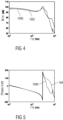
- the use of such a small flat membrane has the disadvantage that at large sound levels, the membrane displacement becomes a nonlinear function of the acoustic pressure, leading to nonlinearities in the reproduced sound (measurable as total harmonic distortion - THD) in the ear canal.
- Another disadvantage is, because the membrane needs to be very compliant, that the membrane can easily get damaged or punctured. Alleviation of this issue requires an increase of the membrane's bending stiffness (either by changing the material properties, or by thickening it) or its pretension. Both aspects will lead to a substantial sound transmission loss - leading to a lower fit-rate as, on average, larger receivers will be required to compensate for the induced acoustic loss.
- a protective element configured to be connected to an electroacoustic transducer or a sound tube included in a hearing device, the protective element comprising a 3D-shaped membrane enclosing a cavity with an opening at which the membrane is configured to connect to the transducer or sound tube, wherein the membrane has one or more thinner portions configured to transmit sound and one or more thicker portions at which a rigidity of the membrane is greater than at the thinner portions.
- the electroacoustic transducer may be any transducer configured to convert electrical signals to sound, or vice versa.
- the transducer is a loudspeaker, for instance a receiver.
- the transducer is a microphone, for instance an ear canal microphone, or a microphone array.
- the thinner portions may more easily be stimulated to vibrate during sound transmission, e.g., with a smaller mechanical damping and/or a larger vibration amplitude, as compared to the thicker portions due to a smaller mass and/or stiffness of the thinner portions.
- a much larger surface can be realized by the 3D-shaped membrane, resulting in improved sound transmission.
- the required acoustic transmission performance may be achieved by the combination of several thinner portions, whereas the mechanical stability is provided by different, thicker portions.
- Further parts may be provided to prevent irritations of the ear canal skin in the case of contact and yet further parts (e.g. a dome) may be provided to ensure a good fit in the ear canal.
- the thinner portions have a thickness of less than 0.2 mm.
- one or more of the thinner portions comprise a region with a thickness of at most 0.1 mm, in particular at most 0.07 mm.
- the thicker portions have a thickness exceeding a thickness of one or more of the thinner portions by at least 0.1 mm.
- one or more of the thicker portions have a thickness of at least 0.3 mm.
- the membrane comprises at least two thinner portions which are angled relative to one another.
- a direction in which one of the at least two thinner portions vibrates may thus be angled relative to a direction in which another one of the at least two thinner portions vibrates when sound is transmitted through the at least two thinner portions.
- a first virtual plane may be defined as a plane extending through a perimeter of one of the at least two thinner portions
- a second virtual plane may be defined as a plane extending through a perimeter of another one of the at least two thinner portions, wherein the first virtual plane and the second virtual plane are angled relative to one another.
- a normal vector of the first virtual plane may be angled relative to a normal vector of the second virtual plane.
- an angle between at least two of the thinner portions is smaller than 180°.
- an angle between at least two of the thinner portions is at most 150°.
- one or more of the thinner portions have a curved shape. In an embodiment, one or more of the thinner portions have a planar shape. E.g., when one or more of the thinner portions have a planar shape, a virtual plane extending through a perimeter of the respective thinner portion may correspond to a surface of the thinner portion. In an embodiment, one or more of the thicker portions are arranged between two or more of the thinner portions. In an embodiment, two or more of the thinner portions are adjoining each other. E.g., two or more of the thinner portions may adjoin each other at an angle at which they are angled relative to one another, e.g., at a corner of the membrane. In an embodiment, one or more of the thicker portions protrude from at least two of the thinner portions at a region of the membrane at which the at least two thinner portions are angled relative to one another, e.g., at a corner of the membrane.
- the lateral wall surrounds the cavity, e.g., along a circumference of the lateral wall.
- the lateral wall and/or the front wall may comprise an inner surface delimiting the cavity and an outer surface opposing the inner surface.
- the outer surface of the lateral wall may define a lateral area of the membrane.
- the outer surface of the front wall may define a bottom of the membrane.
- a central axis of the lateral wall may be defined as an axis extending through the cavity surrounded by the lateral wall between the opening, in particular a center of the opening, and the front wall, in particular a center of the front wall.
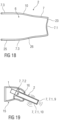
- the membrane is shaped similar to a cup, e.g., beaker-like, with a bottom provided at the front wall and a lateral area provided at the lateral wall.
- the front wall is a thinner portion while the lateral wall near the opening is a thicker portion.
- the lateral wall adjacent the front wall is also a thinner portion.
- the front wall is a thinner portion. In an embodiment, the front wall is planar. In an embodiment, the front wall is curved. In an embodiment, the front wall is curved toward the cavity.
- the lateral wall comprises one or more of the thinner portions.
- one or more of the thinner portions of the lateral wall is planar.
- one or more of the thinner portions of the lateral wall is curved.
- one or more of the thinner portions of the lateral wall is curved away from the cavity, e.g., has a convex curvature.
- one or more of the thinner portions of the lateral wall is curved toward the cavity, e.g., has a concave curvature.
- the lateral wall comprises a portion in which the lateral wall tapers toward the front end. In an embodiment, the lateral wall comprises a portion in which a cross section of the lateral wall remains substantially constant, in particular along a direction of extension in parallel to a central axis.
- the lateral wall comprises one or more of the thinner portions from which one or more of the thicker portions protrude at an outer surface and/or at an inner surface of the lateral wall.
- one or more of the thicker portions may protrude from the thinner portions at a corner region of the lateral wall at which the thinner portions are angled relative to one another and/or one or more of thicker portions may protrude from the thinner portions at a continuous region of the lateral wall at which the thinner portions are continuously joined.
- the one or more thinner portions of the lateral wall define a cylindrical outer surface of the lateral wall, e.g., by disregarding the one or more thicker portions of the lateral wall. In an embodiment, the one or more thinner portions of the lateral wall define a conical outer surface of the lateral wall.
- a stiffness of the membrane can be increased between the thinner portions due to the larger rigidity of thicker portion forming the stiffener in between.
- one or more of the stiffeners are rod-shaped.
- one or more of the stiffeners are provided as fins. Fins may serve for reinforcement and/or for increasing the total sound radiating surface area and/or to obtain certain acoustic-mechanical vibration modes.
- one or more of the stiffeners are formed by one or more of the thicker portions of the lateral wall.
- one or more thicker portions at the lateral wall may constitute stiffeners, in particular to stabilize the lateral wall with regard to a lower stability of the one or more of the thinner portions at the lateral wall as compared to the thicker portions.
- one or more of the stiffeners are formed such that the membrane is configured to contact an ear canal wall at the stiffeners when connected to the electroacoustic transducer or sound tube, and when inserted into an ear canal.
- the stiffeners may thus provide a spacing of the one or more thinner portions at the lateral wall from the surrounding environment, e.g., the ear canal wall, in particular to ensure that vibrations of the thinner portions, e.g., during a sound transmission, are not hindered by the surrounding environment.
- the one or more thicker portions leading to the opening have a different thickness as compared to the thickness of the one or more thicker portions forming the stiffeners.
- the thicker portions leading to the opening may be thicker than at least one of the thicker portions forming the stiffeners.
- the thicker portions leading to the opening and the thicker portions forming the stiffeners have an equal thickness.
- At least two of the stiffeners are spaced from one another along a circumference of the lateral wall.
- a plurality of the stiffeners e.g., at least three of the stiffeners, are distributed around the circumference of the lateral wall.
- the stiffeners are equidistantly spaced from one another around the circumference of the lateral wall.
- the membrane has a star-like cross section due to a plurality of the stiffeners being arranged on the outside of the lateral wall.
- the membrane has a cross section approximating a polygon with edges joined at corners, wherein the corners are formed by at least part of the thicker portions, e.g., the stiffeners, and the edges comprise at least part of the thinner portions.
- the edges may be formed by at least part of the thinner portions and/or the edges may comprise at least one thicker portion in addition to one or more thinner portions.
- the polygon is equilateral such that the edges have an equal length.
- the polygon is equiangular such that the angles at the corners are equal.
- the angles at two or more of the corners are different.
- an angle at one or more of the corners may be larger than 90°, and an angle at one or more other corners may be smaller than 90°.
- one or more of the edges are curved. In an embodiment, one or more of the edges are planar.
- the membrane has a cross section approximating a rhombus with four corners formed by respective stiffeners.
- the cross section may be a four lobe cross section.
- the diameter across two opposing ones of the corners is greater than the diameter across the two other opposing corners.
- at least part of the edges between the corners are concave. In an embodiment, at least part of the edges between the corners are convex.
- the membrane is formed by injection molding of liquid silicone rubber (LSR).
- LSR liquid silicone rubber
- one or more reinforcement parts made out of a different material than the membrane are arranged on the outside and/or on the inside of the membrane.
- one or more of the reinforcement parts extend between the thinner portions on the outside and/or on the inside of the membrane.
- a stiffness of the membrane can be increased between the thinner portions due to the larger rigidity provided by a support of the reinforcement parts. In this way, an overall stability of the membrane can be enhanced.
- the different material is a thermoplastic.
- the one or more reinforcement parts may be applied by overmolding the different material on the membrane.
- one or more reinforcement parts are arranged on one or more of the stiffeners, e.g. in the shape of an additional rib on the fins. In an embodiment, a respective reinforcement part is arranged on two opposite ones of the stiffeners. In an embodiment, the one or more reinforcement parts may be provided by overmolding the different material on one or more of the stiffeners, e.g., by a thermoplastic overmolding.
- one or more of the reinforcement parts are arranged on the lateral wall, e.g., at the outer surface and/or at the inner surface of the lateral wall. In this way, the lateral wall may be stabilized with regard to a lower stability of the one or more of the thinner portions at the lateral wall as compared to the thicker portions.
- one or more of the reinforcement parts are formed such that the membrane is configured to contact an ear canal wall at the reinforcement parts when connected to the electroacoustic transducer or sound tube, and when inserted into an ear canal.
- the reinforcement parts may thus provide a spacing of the one or more thinner portions at the lateral wall from the surrounding environment, e.g., the ear canal wall.
- one or more of the reinforcement parts extend in parallel to a central axis of the lateral wall. In an embodiment, one or more of the reinforcement parts are rod-shaped, in particular in the shape of a rib. In an embodiment, one or more of the reinforcement parts extend at least partially around a circumference of the lateral wall.
- At least one reinforcement part made out of a different material than the membrane is arranged within the cavity to internally support the membrane.
- the reinforcement part is arranged within the cavity to internally support the membrane at a position of one or more of the stiffeners.
- the reinforcement part is configured as a structure extending between two supported stiffeners.
- the reinforcement part has a planar structure.
- the reinforcement part has a rectangular shape.
- the reinforcement part is provided with a cut out facing the front wall and/or a cut out facing the opening. E.g., the cut out may be a circular sector cut out.
- the membrane is made of a single material or multiple materials, e.g. silicone rubber and/or another polymer with Young's modulus less than 10 MPa, in particular less than 5 MPa, e.g., less than 3 MPa, and/or being provided with a coating repellent to cerumen.
- a length of the thinner portions of the lateral wall is at least 2 mm and/or at most 10 mm.
- a diameter of the membrane, in particular of the front wall is at most 7 mm.
- a thickness of the thinner portions is 0.05 mm or below, at least for the thinnest parts.
- a perimeter of a front wall of the membrane has a rounded shape.
- the rounded shape of the perimeter of the front wall may facilitate an insertion of the protective element into an ear canal and/or ensure a good wearing comfort inside the ear canal, e.g., when the perimeter contacts the ear canal wall.
- the rounded shape may be provided as a rounded structure arranged circumferentially around the perimeter.
- the thinner portions constitute a surface of the membrane of at least 30 mm 2 .
- the thinner portions constitute a surface of the membrane, e.g. a portion of the outer surface of the membrane, of at least 40 mm 2 , in particular at least 50 mm 2 .
- a sound transmission through the protective element may be effectively increased, in particular by exploiting the 3D shape of the membrane.
- the membrane further comprises at least one dome configured for sealing against an ear canal, wherein the at least one dome is integrally formed with the membrane.
- the hearing device is configured to be worn at an ear of a user.
- the hearing device is configured to be at least partially inserted into an ear canal of a user.
- the hearing device may include an earpiece configured for at least partial insertion into the ear canal.
- the earpiece may comprise a shell customized to a shape of an individual ear canal of the user.
- the earpiece may comprise a flexible member, e.g., a dome, which can conform its shape to the shape of the individual ear canal.
- the electroacoustic transducer and/or the sound tube is included in the earpiece.
- the hearing device comprises a housing configured to be worn behind an ear of a user.
- the electroacoustic transducer is included in the housing configured to be worn behind the ear.
Landscapes
- Engineering & Computer Science (AREA)
- Physics & Mathematics (AREA)
- Acoustics & Sound (AREA)
- Signal Processing (AREA)
- Health & Medical Sciences (AREA)
- General Health & Medical Sciences (AREA)
- Neurosurgery (AREA)
- Otolaryngology (AREA)
- Manufacturing & Machinery (AREA)
- Headphones And Earphones (AREA)
- Diaphragms For Electromechanical Transducers (AREA)
- Obtaining Desirable Characteristics In Audible-Bandwidth Transducers (AREA)
Priority Applications (1)
| Application Number | Priority Date | Filing Date | Title |
|---|---|---|---|
| EP25174552.7A EP4576832A3 (de) | 2022-08-22 | 2022-08-22 | Schutzelement für einen elektroakustischen wandler eines hörgerätes oder für einen schallschlauch in einem hörgerät |
Applications Claiming Priority (2)
| Application Number | Priority Date | Filing Date | Title |
|---|---|---|---|
| EP22191488.0A EP4329334B1 (de) | 2022-08-22 | 2022-08-22 | Schutzelement für einen elektroakustischen wandler eines hörgerätes oder für einen schallschlauch in einem hörgerät |
| EP25174552.7A EP4576832A3 (de) | 2022-08-22 | 2022-08-22 | Schutzelement für einen elektroakustischen wandler eines hörgerätes oder für einen schallschlauch in einem hörgerät |
Related Parent Applications (2)
| Application Number | Title | Priority Date | Filing Date |
|---|---|---|---|
| EP22191488.0A Division EP4329334B1 (de) | 2022-08-22 | 2022-08-22 | Schutzelement für einen elektroakustischen wandler eines hörgerätes oder für einen schallschlauch in einem hörgerät |
| EP22191488.0A Division-Into EP4329334B1 (de) | 2022-08-22 | 2022-08-22 | Schutzelement für einen elektroakustischen wandler eines hörgerätes oder für einen schallschlauch in einem hörgerät |
Publications (2)
| Publication Number | Publication Date |
|---|---|
| EP4576832A2 true EP4576832A2 (de) | 2025-06-25 |
| EP4576832A3 EP4576832A3 (de) | 2025-09-24 |
Family
ID=83005974
Family Applications (2)
| Application Number | Title | Priority Date | Filing Date |
|---|---|---|---|
| EP25174552.7A Pending EP4576832A3 (de) | 2022-08-22 | 2022-08-22 | Schutzelement für einen elektroakustischen wandler eines hörgerätes oder für einen schallschlauch in einem hörgerät |
| EP22191488.0A Active EP4329334B1 (de) | 2022-08-22 | 2022-08-22 | Schutzelement für einen elektroakustischen wandler eines hörgerätes oder für einen schallschlauch in einem hörgerät |
Family Applications After (1)
| Application Number | Title | Priority Date | Filing Date |
|---|---|---|---|
| EP22191488.0A Active EP4329334B1 (de) | 2022-08-22 | 2022-08-22 | Schutzelement für einen elektroakustischen wandler eines hörgerätes oder für einen schallschlauch in einem hörgerät |
Country Status (3)
| Country | Link |
|---|---|
| US (3) | US12389176B2 (de) |
| EP (2) | EP4576832A3 (de) |
| CN (1) | CN117615289A (de) |
Family Cites Families (12)
| Publication number | Priority date | Publication date | Assignee | Title |
|---|---|---|---|---|
| US4953215A (en) | 1989-10-05 | 1990-08-28 | Siemens Aktiengesellschaft | Arrangement to prevent the intrusion of foreign matter into an electro-acoustical transducer |
| DE19640796A1 (de) * | 1996-10-02 | 1998-04-16 | Siemens Audiologische Technik | Schutzvorrichtung für die Schallein- und/oder Schallaustrittsöffnung an Gehäusen oder Ohrpaßstücken von Hörhilfegeräten |
| US6473513B1 (en) | 1999-06-08 | 2002-10-29 | Insonus Medical, Inc. | Extended wear canal hearing device |
| US7664282B2 (en) | 1998-11-25 | 2010-02-16 | Insound Medical, Inc. | Sealing retainer for extended wear hearing devices |
| WO2009056167A1 (en) | 2007-10-30 | 2009-05-07 | 3Win N.V. | Body-worn wireless transducer module |
| EP2944096B1 (de) * | 2013-01-11 | 2021-08-04 | Sonova AG | Schale für eine hörvorrichtung |
| DK3025511T3 (da) | 2013-07-22 | 2020-03-23 | Sonova Ag | Høreapparat med forbedret lav frekvensrespons samt metoden for fremstillingen af sagte høreapparat |
| DK3142386T3 (da) | 2015-09-08 | 2019-07-08 | Oticon As | Tætningsørestykke |
| WO2018228988A1 (en) | 2017-06-16 | 2018-12-20 | Widex A/S | Flexible ear piece for a hearing aid |
| US11228851B2 (en) | 2017-11-28 | 2022-01-18 | Sonova Ag | Cerumen protection plug |
| DE102018107195B3 (de) | 2018-02-05 | 2019-02-14 | Paul Gregor Junke | Universal Silikon-Softadapter für Hörgeräte |
| CN112823533B (zh) * | 2018-10-03 | 2022-06-21 | 纱帝股份公司 | 用于音频设备的透声保护器及音频设备 |
-
2022
- 2022-08-22 EP EP25174552.7A patent/EP4576832A3/de active Pending
- 2022-08-22 EP EP22191488.0A patent/EP4329334B1/de active Active
-
2023
- 2023-07-20 CN CN202310897974.3A patent/CN117615289A/zh active Pending
- 2023-08-14 US US18/233,491 patent/US12389176B2/en active Active
-
2024
- 2024-10-09 US US18/910,219 patent/US12231855B1/en active Active
-
2025
- 2025-05-28 US US19/220,596 patent/US20250294301A1/en active Pending
Also Published As
| Publication number | Publication date |
|---|---|
| US12389176B2 (en) | 2025-08-12 |
| US20240064481A1 (en) | 2024-02-22 |
| EP4576832A3 (de) | 2025-09-24 |
| US12231855B1 (en) | 2025-02-18 |
| EP4329334A1 (de) | 2024-02-28 |
| US20250294301A1 (en) | 2025-09-18 |
| US20250039619A1 (en) | 2025-01-30 |
| CN117615289A (zh) | 2024-02-27 |
| EP4329334C0 (de) | 2025-07-02 |
| EP4329334B1 (de) | 2025-07-02 |
Similar Documents
| Publication | Publication Date | Title |
|---|---|---|
| US7113611B2 (en) | Disposable modular hearing aid | |
| US7403629B1 (en) | Disposable modular hearing aid | |
| JP4839016B2 (ja) | 補聴器用柔軟性耳当て | |
| US20070071265A1 (en) | Disposable modular hearing aid | |
| CN105705119B (zh) | 外耳配合式电子听力保护装置 | |
| US7082206B2 (en) | Flexible hearing aid tip with an integral receiver | |
| EP2076064B1 (de) | Hörvorrichtung mit Hörgeräte-Otoplastik und Ausgangsmodul | |
| US12413919B2 (en) | Wax protection for in-canal hearing device | |
| EP1175811B1 (de) | Wegwerfbares modulares hörhilfegerät | |
| US12231855B1 (en) | Protective element for an electroacoustic transducer of a hearing device or for a sound tube included in a hearing device | |
| US11178497B2 (en) | In-ear receiver | |
| KR20140068629A (ko) | 무통증 이어폰 | |
| WO2001069973A2 (en) | Disposable modular hearing aid | |
| US20250211921A1 (en) | Hearing device comprising a mechanical element for sound transmission | |
| US20250287162A1 (en) | Hearing device comprising a mechanical element for sound transmission | |
| CN114640915A (zh) | 入耳式声学装置 | |
| CN121128191A (zh) | 用于听力设备的耳塞和听力设备 | |
| CN101180918A (zh) | 用于助听器的钩状物 | |
| HK1208111B (en) | An earphone having a controlled acoustic leak port | |
| HK1171891B (en) | Earphones | |
| HK1208111A1 (en) | An earphone having a controlled acoustic leak port |
Legal Events
| Date | Code | Title | Description |
|---|---|---|---|
| PUAI | Public reference made under article 153(3) epc to a published international application that has entered the european phase |
Free format text: ORIGINAL CODE: 0009012 |
|
| STAA | Information on the status of an ep patent application or granted ep patent |
Free format text: STATUS: THE APPLICATION HAS BEEN PUBLISHED |
|
| AC | Divisional application: reference to earlier application |
Ref document number: 4329334 Country of ref document: EP Kind code of ref document: P |
|
| AK | Designated contracting states |
Kind code of ref document: A2 Designated state(s): AL AT BE BG CH CY CZ DE DK EE ES FI FR GB GR HR HU IE IS IT LI LT LU LV MC MK MT NL NO PL PT RO RS SE SI SK SM TR |
|
| PUAL | Search report despatched |
Free format text: ORIGINAL CODE: 0009013 |
|
| AK | Designated contracting states |
Kind code of ref document: A3 Designated state(s): AL AT BE BG CH CY CZ DE DK EE ES FI FR GB GR HR HU IE IS IT LI LT LU LV MC MK MT NL NO PL PT RO RS SE SI SK SM TR |
|
| RIC1 | Information provided on ipc code assigned before grant |
Ipc: H04R 25/00 20060101AFI20250820BHEP Ipc: H04R 1/10 20060101ALI20250820BHEP |