EP4329334B1 - Schutzelement für einen elektroakustischen wandler eines hörgerätes oder für einen schallschlauch in einem hörgerät - Google Patents
Schutzelement für einen elektroakustischen wandler eines hörgerätes oder für einen schallschlauch in einem hörgerät Download PDFInfo
- Publication number
- EP4329334B1 EP4329334B1 EP22191488.0A EP22191488A EP4329334B1 EP 4329334 B1 EP4329334 B1 EP 4329334B1 EP 22191488 A EP22191488 A EP 22191488A EP 4329334 B1 EP4329334 B1 EP 4329334B1
- Authority
- EP
- European Patent Office
- Prior art keywords
- membrane
- protective element
- portions
- lateral wall
- thinner portions
- Prior art date
- Legal status (The legal status is an assumption and is not a legal conclusion. Google has not performed a legal analysis and makes no representation as to the accuracy of the status listed.)
- Active
Links
Images


Classifications
-
- H—ELECTRICITY
- H04—ELECTRIC COMMUNICATION TECHNIQUE
- H04R—LOUDSPEAKERS, MICROPHONES, GRAMOPHONE PICK-UPS OR LIKE ACOUSTIC ELECTROMECHANICAL TRANSDUCERS; DEAF-AID SETS; PUBLIC ADDRESS SYSTEMS
- H04R25/00—Deaf-aid sets, i.e. electro-acoustic or electro-mechanical hearing aids; Electric tinnitus maskers providing an auditory perception
- H04R25/60—Mounting or interconnection of hearing aid parts, e.g. inside tips, housings or to ossicles
-
- H—ELECTRICITY
- H04—ELECTRIC COMMUNICATION TECHNIQUE
- H04R—LOUDSPEAKERS, MICROPHONES, GRAMOPHONE PICK-UPS OR LIKE ACOUSTIC ELECTROMECHANICAL TRANSDUCERS; DEAF-AID SETS; PUBLIC ADDRESS SYSTEMS
- H04R25/00—Deaf-aid sets, i.e. electro-acoustic or electro-mechanical hearing aids; Electric tinnitus maskers providing an auditory perception
- H04R25/65—Housing parts, e.g. shells, tips or moulds, or their manufacture
- H04R25/652—Ear tips; Ear moulds
- H04R25/654—Ear wax retarders
-
- H—ELECTRICITY
- H04—ELECTRIC COMMUNICATION TECHNIQUE
- H04R—LOUDSPEAKERS, MICROPHONES, GRAMOPHONE PICK-UPS OR LIKE ACOUSTIC ELECTROMECHANICAL TRANSDUCERS; DEAF-AID SETS; PUBLIC ADDRESS SYSTEMS
- H04R1/00—Details of transducers, loudspeakers or microphones
- H04R1/10—Earpieces; Attachments therefor ; Earphones; Monophonic headphones
- H04R1/1016—Earpieces of the intra-aural type
-
- H—ELECTRICITY
- H04—ELECTRIC COMMUNICATION TECHNIQUE
- H04R—LOUDSPEAKERS, MICROPHONES, GRAMOPHONE PICK-UPS OR LIKE ACOUSTIC ELECTROMECHANICAL TRANSDUCERS; DEAF-AID SETS; PUBLIC ADDRESS SYSTEMS
- H04R25/00—Deaf-aid sets, i.e. electro-acoustic or electro-mechanical hearing aids; Electric tinnitus maskers providing an auditory perception
- H04R25/65—Housing parts, e.g. shells, tips or moulds, or their manufacture
- H04R25/652—Ear tips; Ear moulds
- H04R25/656—Non-customized, universal ear tips, i.e. ear tips which are not specifically adapted to the size or shape of the ear or ear canal
-
- H—ELECTRICITY
- H04—ELECTRIC COMMUNICATION TECHNIQUE
- H04R—LOUDSPEAKERS, MICROPHONES, GRAMOPHONE PICK-UPS OR LIKE ACOUSTIC ELECTROMECHANICAL TRANSDUCERS; DEAF-AID SETS; PUBLIC ADDRESS SYSTEMS
- H04R2225/00—Details of deaf aids covered by H04R25/00, not provided for in any of its subgroups
- H04R2225/023—Completely in the canal [CIC] hearing aids
-
- H—ELECTRICITY
- H04—ELECTRIC COMMUNICATION TECHNIQUE
- H04R—LOUDSPEAKERS, MICROPHONES, GRAMOPHONE PICK-UPS OR LIKE ACOUSTIC ELECTROMECHANICAL TRANSDUCERS; DEAF-AID SETS; PUBLIC ADDRESS SYSTEMS
- H04R2225/00—Details of deaf aids covered by H04R25/00, not provided for in any of its subgroups
- H04R2225/025—In the ear hearing aids [ITE] hearing aids
-
- H—ELECTRICITY
- H04—ELECTRIC COMMUNICATION TECHNIQUE
- H04R—LOUDSPEAKERS, MICROPHONES, GRAMOPHONE PICK-UPS OR LIKE ACOUSTIC ELECTROMECHANICAL TRANSDUCERS; DEAF-AID SETS; PUBLIC ADDRESS SYSTEMS
- H04R2225/00—Details of deaf aids covered by H04R25/00, not provided for in any of its subgroups
- H04R2225/77—Design aspects, e.g. CAD, of hearing aid tips, moulds or housings
-
- H—ELECTRICITY
- H04—ELECTRIC COMMUNICATION TECHNIQUE
- H04R—LOUDSPEAKERS, MICROPHONES, GRAMOPHONE PICK-UPS OR LIKE ACOUSTIC ELECTROMECHANICAL TRANSDUCERS; DEAF-AID SETS; PUBLIC ADDRESS SYSTEMS
- H04R2460/00—Details of hearing devices, i.e. of ear- or headphones covered by H04R1/10 or H04R5/033 but not provided for in any of their subgroups, or of hearing aids covered by H04R25/00 but not provided for in any of its subgroups
- H04R2460/11—Aspects relating to vents, e.g. shape, orientation, acoustic properties in ear tips of hearing devices to prevent occlusion
Definitions
- the invention relates to a membrane for a receiver of a hearing device.
- transducer In hearing instruments, a notorious issue is that substances such as liquids, cerumen or dirt may enter a transducer, e.g. a receiver, or a receiver tube, which could lead to transducer malfunctioning and deterioration in hearing performance. This can range from slightly distorted acoustic signals to a total failure of the transducer. Transducer failure is the most frequent reason for servicing of hearing instruments.
- An example of an acoustically closed transducer protection system might be a flat membrane.
- the use of such a small flat membrane has the disadvantage that at large sound levels, the membrane displacement becomes a nonlinear function of the acoustic pressure, leading to nonlinearities in the reproduced sound (measurable as total harmonic distortion - THD) in the ear canal.
- Another disadvantage is, because the membrane needs to be very compliant, that the membrane can easily get damaged or punctured. Alleviation of this issue requires an increase of the membrane's bending stiffness (either by changing the material properties, or by thickening it) or its pre-tension. Both aspects will lead to a substantial sound transmission loss - leading to a lower fit-rate as, on average, larger receivers will be required to compensate for the induced acoustic loss.
- US 2021/0258705 A1 describes an acoustically transparent protector for an audio device provided with a sound generating transducer having a sound port covered by said protector for use with a human ear for the reproduction of sound which allows sound to pass through with little attenuation or distortion but does not allow foreign material such as ear wax. dust, debris, or water to pass into the sound port.
- the protector is provided with a sound radiating element having at least a curve portion and a suspension part. The protector realizes a barrier that attenuates the sound entering the audio device as little as possible and does not suffer from significant sound distortions.
- EP 0 835 042 A2 describes a protective device including a membrane which covers an aperture in a casing or ear piece of a hearing aid, which is provided for an entry or output of sound.
- a closed, thin-walled membrane of a same wall thickness is provided, which consists of an inert material suitable for sound transmission.
- the membrane is preferably a thin titanium membrane with a wall thickness of 0.01 mm.
- the membrane may be arranged in a cap, a sheath, or a ring, and may have a concave, convex or flat form.
- the membrane preferably includes a surface engraving, formed of concentric rings or a spiral.
- a protective element configured to be connected to an electroacoustic transducer or a sound tube included in a hearing device, the protective element comprising a 3D-shaped membrane enclosing a cavity with an opening at which the membrane is configured to connect to the transducer or sound tube, wherein the membrane has one or more thinner portions configured to transmit sound and one or more thicker portions at which a rigidity of the membrane is greater than at the thinner portions.
- the electroacoustic transducer may be any transducer configured to convert electrical signals to sound, or vice versa.
- the transducer is a loudspeaker, for instance a receiver.
- the transducer is a microphone, for instance an ear canal microphone, or a microphone array.
- the thinner portions are predominantly configured to transmit sound
- the thicker portions are predominantly configured to provide for a mechanical stabilization of the membrane and/or an attachment of the membrane to the transducer or sound tube and/or portions configured to align with the ear canal.
- the attachment may be provided by at least one of the thicker portions positioned at the opening.
- the membrane may be configured such that an intensity of sound transmitted through the membrane is larger at the thinner portions as compared to the thicker portions.
- the thinner portions may more easily be stimulated to vibrate during sound transmission, e.g., with a smaller mechanical damping and/or a larger vibration amplitude, as compared to the thicker portions due to a smaller mass and/or stiffness of the thinner portions.
- the thinner portions have a thickness of less than 0.2 mm.
- one or more of the thinner portions comprise a region with a thickness of at most 0.1 mm, in particular at most 0.07 mm.
- the thicker portions have a thickness exceeding a thickness of one or more of the thinner portions by at least 0.1 mm.
- one or more of the thicker portions have a thickness of at least 0.3 mm.
- the membrane comprises at least two thinner portions which are angled relative to one another.
- a direction in which one of the at least two thinner portions vibrates may thus be angled relative to a direction in which another one of the at least two thinner portions vibrates when sound is transmitted through the at least two thinner portions.
- a first virtual plane may be defined as a plane extending through a perimeter of one of the at least two thinner portions
- a second virtual plane may be defined as a plane extending through a perimeter of another one of the at least two thinner portions, wherein the first virtual plane and the second virtual plane are angled relative to one another.
- a normal vector of the first virtual plane may be angled relative to a normal vector of the second virtual plane.
- an angle between at least two of the thinner portions is smaller than 180°.
- an angle between at least two of the thinner portions is at most 150°.
- one or more of the thinner portions have a curved shape. In an embodiment, one or more of the thinner portions have a planar shape. E.g., when one or more of the thinner portions have a planar shape, a virtual plane extending through a perimeter of the respective thinner portion may correspond to a surface of the thinner portion. In an embodiment, one or more of the thicker portions are arranged between two or more of the thinner portions. In an embodiment, two or more of the thinner portions are adjoining each other. E.g., two or more of the thinner portions may adjoin each other at an angle at which they are angled relative to one another, e.g., at a corner of the membrane. In an embodiment, one or more of the thicker portions protrude from at least two of the thinner portions at a region of the membrane at which the at least two thinner portions are angled relative to one another, e.g., at a corner of the membrane.
- the membrane comprises a front wall at a front end opposing a rear end at which the opening is provided, and a lateral wall extending between the front wall and the opening, wherein the lateral wall comprises at least one of the thicker portions and one or more of the thinner portions.
- the lateral wall surrounds the cavity, e.g., along a circumference of the lateral wall.
- the lateral wall and/or the front wall may comprise an inner surface delimiting the cavity and an outer surface opposing the inner surface.
- the outer surface of the lateral wall may define a lateral area of the membrane.
- the outer surface of the front wall may define a bottom of the membrane.
- a central axis of the lateral wall may be defined as an axis extending through the cavity surrounded by the lateral wall between the opening, in particular a center of the opening, and the front wall, in particular a center of the front wall.
- the front wall is a thinner portion. In an embodiment, the front wall is planar. In an embodiment, the front wall is curved. In an embodiment, the front wall is curved toward the cavity.
- the lateral wall comprises one or more of the thinner portions.
- one or more of the thinner portions of the lateral wall is planar.
- one or more of the thinner portions of the lateral wall is curved.
- one or more of the thinner portions of the lateral wall is curved away from the cavity, e.g., has a convex curvature.
- one or more of the thinner portions of the lateral wall is curved toward the cavity, e.g., has a concave curvature.
- an angle between one or more thinner portions of the front end and one or more thinner portions of the lateral wall is at least 90°. In an embodiment, an angle in between two or more thinner portions of the lateral wall is at most 150°. In an embodiment, an angle in between two or more thinner portions of the lateral wall is larger than 90°. In an embodiment, an angle in between two or more other thinner portions of the lateral wall is smaller than 90°.
- the one or more thinner portions at the lateral wall are predominantly configured to provide for a transmission of sound.
- an area of the membrane which is predominantly configured for sound transmission may be provided by one or more thinner portions at the lateral wall and/or by one or more thinner portions at the front wall.
- the predominantly sound transmissible area may be increased by one or more thinner portions at the front wall and at the lateral wall as compared to when the one or more thinner portions are solely provided at the front wall or at the lateral wall.
- the thicker portions may also be configured for sound transmission, e.g., to a lesser extent than the thinner portions. A sound transmissible area of the membrane may thus be provided by one or more thinner portions and one or more thicker portions.
- the lateral wall comprises one or more of the thinner portions from which one or more of the thicker portions protrude at an outer surface and/or at an inner surface of the lateral wall.
- one or more of the thicker portions protrude from the thinner portions at a corner region of the lateral wall at which the thinner portions are angled relative to one another and/or one or more of thicker portions protrude from the thinner portions at a continuous region of the lateral wall at which the thinner portions are continuously joined.
- At least one of the thinner portions of the lateral wall has a different thickness as compared to the thickness of at least one of the thinner portions of the front wall.
- the front wall may be thinner than at least one of the thinner portions of the lateral wall.
- at least one of the thinner portions of the lateral wall and at least one of the thinner portions of the front wall have an equal thickness.
- the one or more thinner portions of the lateral wall define a cylindrical outer surface of the lateral wall, e.g., by disregarding the one or more thicker portions of the lateral wall. In an embodiment, the one or more thinner portions of the lateral wall define a conical outer surface of the lateral wall.
- the thicker portion leading to the opening may be configured to provide for an attachment of the membrane to the transducer or sound tube.
- the rigidity of the membrane may be enhanced at the opening by the thicker portion leading to the opening such that a stable attachment can be achieved, e.g., without risking damaging of the membrane.
- the thicker portion leading to the opening extends around a circumference of the lateral wall. In particular, when the thicker portion leading to the opening extends around a circumference of the lateral wall, a uniform stability of the attachment and/or a minimum risk of damaging the membrane may be realized.
- one or more stiffeners are formed by one or more of the thicker portions extending between the thinner portions on the outside and/or on the inside of the membrane.
- a stiffness of the membrane can be increased between the thinner portions due to the larger rigidity of thicker portion forming the stiffener in between.
- one or more of the stiffeners are rod-shaped.
- one or more of the stiffeners are provided as fins. Fins may serve for reinforcement and/or for increasing the total sound radiating surface area and/or to obtain certain acoustic-mechanical vibration modes.
- the membrane has a star-like cross section due to a plurality of the stiffeners being arranged on the outside of the lateral wall.
- the membrane has a cross section approximating a rhombus with four corners formed by respective stiffeners.
- the cross section may be a four lobe cross section.
- the diameter across two opposing ones of the corners is greater than the diameter across the two other opposing corners.
- at least part of the edges between the corners are concave. In an embodiment, at least part of the edges between the corners are convex.
- the membrane is formed by injection molding of liquid silicone rubber (LSR).
- LSR liquid silicone rubber
- one or more reinforcement parts made out of a different material than the membrane are arranged on the outside and/or on the inside of the membrane.
- one or more of the reinforcement parts extend between the thinner portions on the outside and/or on the inside of the membrane.
- a stiffness of the membrane can be increased between the thinner portions due to the larger rigidity provided by a support of the reinforcement parts. In this way, an overall stability of the membrane can be enhanced.
- the different material is a thermoplastic.
- the one or more reinforcement parts may be applied by overmolding the different material on the membrane.
- one or more reinforcement parts are arranged on one or more of the stiffeners, e.g. in the shape of an additional rib on the fins. In an embodiment, a respective reinforcement part is arranged on two opposite ones of the stiffeners. In an embodiment, the one or more reinforcement parts may be provided by overmolding the different material on one or more of the stiffeners, e.g., by a thermoplastic overmolding.
- one or more of the reinforcement parts are arranged on the lateral wall, e.g., at the outer surface and/or at the inner surface of the lateral wall. In this way, the lateral wall may be stabilized with regard to a lower stability of the one or more of the thinner portions at the lateral wall as compared to the thicker portions.
- one or more of the reinforcement parts are formed such that the membrane is configured to contact an ear canal wall at the reinforcement parts when connected to the electroacoustic transducer or sound tube, and when inserted into an ear canal.
- the reinforcement parts may thus provide a spacing of the one or more thinner portions at the lateral wall from the surrounding environment, e.g., the ear canal wall.
- one or more of the reinforcement parts extend in parallel to a central axis of the lateral wall. In an embodiment, one or more of the reinforcement parts are rod-shaped, in particular in the shape of a rib. In an embodiment, one or more of the reinforcement parts extend at least partially around a circumference of the lateral wall.
- At least one reinforcement part made out of a different material than the membrane is arranged within the cavity to internally support the membrane.
- the reinforcement part is arranged within the cavity to internally support the membrane at a position of one or more of the stiffeners.
- the reinforcement part is configured as a structure extending between two supported stiffeners.
- the reinforcement part has a planar structure.
- the reinforcement part has a rectangular shape.
- the reinforcement part is provided with a cut out facing the front wall and/or a cut out facing the opening. E.g., the cut out may be a circular sector cut out.
- the membrane is made of a single material or multiple materials, e.g. silicone rubber and/or another polymer with Young's modulus less than 10 MPa, in particular less than 5 MPa, e.g., less than 3 MPa, and/or being provided with a coating repellent to cerumen.
- a length of the thinner portions of the lateral wall is at least 2 mm and/or at most 10 mm.
- a diameter of the membrane, in particular of the front wall is at most 7 mm.
- a thickness of the thinner portions is 0.05 mm or below, at least for the thinnest parts.
- a perimeter of a front wall of the membrane has a rounded shape.
- the rounded shape of the perimeter of the front wall may facilitate an insertion of the protective element into an ear canal and/or ensure a good wearing comfort inside the ear canal, e.g., when the perimeter contacts the ear canal wall.
- the rounded shape may be provided as a rounded structure arranged circumferentially around the perimeter.
- the hearing device is configured to be worn at an ear of a user.
- the hearing device is configured to be at least partially inserted into an ear canal of a user.
- the hearing device may include an earpiece configured for at least partial insertion into the ear canal.
- the earpiece may comprise a shell customized to a shape of an individual ear canal of the user.
- the earpiece may comprise a flexible member, e.g., a dome, which can conform its shape to the shape of the individual ear canal.
- the electroacoustic transducer and/or the sound tube is included in the earpiece.
- the hearing device comprises a housing configured to be worn behind an ear of a user.
- the electroacoustic transducer is included in the housing configured to be worn behind the ear.
- the membrane comprises one or more recesses arranged along an inner surface of the membrane, wherein the one or more recesses are configured to engage a corresponding number of protrusions on an outer surface of the electroacoustic transducer or the sound tube.
- the recess and the protrusion may be ring-shaped.
- the protrusion may extend around an outer circumference of the electroacoustic transducer or the sound tube.
- the recess may be arranged closed to the opening of the membrane.
- the hearing device comprises the protective element as described above, in particular the one having the at least one reinforcement part made out of a different material than the membrane arranged within the cavity to internally support the membrane, wherein the at least one reinforcement part comprises a portion of the electroacoustic transducer or the sound tube extending into the cavity.
- the protection element may be pulled over the portion extending into the cavity.
- one or more of the thicker portions protruding at an inner surface of the lateral wall, in particular at least one of the stiffeners, may contact an outer surface of the electroacoustic transducer or the sound tube constituting the reinforcement part.
- the one or more thinner portions of the lateral wall may be configured to vibrate during sound transmission without being blocked or damped by the outer surface of the electroacoustic transducer or the sound tube which is contacting the membrane at the one or more of the thicker portions.
- the protective element may be mounted to the transducer or sound tube by means of screwing and/or clamping.
- the shape of the protection element may be such that the corners of the protection element protect the thinner portions to be in contact with the ear canal wall so that their vibration is not hindered.
- the protection element may be located fully inside a shell, instead of protruding into the ear canal.
- the transducer used with the protection element may be a microphone.
- the protective element may be a 2K overmolded part, in particular having a hard core and a softer portion, wherein the core may serve for pressure equalization.
- Figure 1 is a schematic view of a transducer 1 for a hearing device.
- the protective element 2 can be mounted to the transducer 1, e.g., on a sound outlet port or sound tube 3 thereof.
- the mounting may be achieved by a recess 4, e.g. a circular recess 4, along an inner surface of the 3D-shaped protective element 2 which engages with a corresponding protrusion 5, e.g. a ring-shaped protrusion 5, on an outer circumference of the sound tube 3 of the transducer 1.
- the transducer 1 or sound tube 3 may extend into the cavity 6, wherein a portion of the electroacoustic transducer 1 or the sound tube 3 extending into the cavity 6 may constitute a reinforcement part to internally support the membrane 7.
- the membrane 7 of the 3D-shaped protective element 2 may have a varying thickness, with thinner portions 7.1 being predominantly employed to transmit sound and thicker portions 7.2 predominantly providing a different functionality, e.g., stabilizing the structure and/or maintaining a desired shape of the 3D-shaped protective element 2, also during sound transmission.
- the thinner portions 7.1 may more easily be stimulated to vibrate during sound transmission, e.g., with a smaller mechanical damping and/or a larger vibration amplitude, as compared to the thicker portions 7.2 due to a smaller mass of the thinner portions 7.1.
- the required acoustic transmission performance may be achieved by the combination of several thinner portions 7.1, whereas the mechanical stability is provided by different, thicker portions 7.2. Further parts may be provided to prevent irritations of the ear canal skin in the case of contact and yet further parts (e.g. a dome) may be provided to ensure a good fit in the ear canal.
- An advantage of the present invention is the possibility to adapt the geometry of the acoustically active elements of the protective element 2.
- the designers have the freedom to place an additional resonance in the acoustic chain, something that is desired to obtain improved acoustic signal output in a certain frequency band.
- the exact geometry may be optimized to match the required acoustic performance. If necessary, a mesh or a foam with open cells may be included in the inside, e.g. in the cavity 6, to enhance the performance.
- mechanical stability may be improved by stiffeners 7.3, e.g. fins 7.3, either on the outside or the inside of the protective element 2.
- a second component e.g. a mechanical element inside the protection element, e.g. included by overmolding a thermoplastic component, can as well be added to meet the stability criteria.
- the transducer tube or sound tube 3 may also be prolonged, e.g. protrude into the cavity 6 and/or the protective element 2 may be mounted at a distance from the end of the sound tube 3, and used as an additional mechanical support.
- the outside of the protective element 2 may be designed without sharp edges that cause irritations when brought in contact with the skin of the ear canal., e.g., during insertion of an earpiece.
- the edges may have a shape such that corner regions of the membrane protect the thinner portions to be in contact with the ear canal wall so that their vibration is not hindered.
- the edges may be rounded edges.
- Figure 4 is a schematic diagram of the magnitude M over the frequency f, wherein a curve 1MC relates to the medium transducer equipped with a conventional filter and a curve 1MN relates to the medium transducer equipped with the protective element 2 according to the invention.
- Figure 5 is a schematic diagram of the phase P over the frequency f, wherein a curve 1MC relates to the medium transducer equipped with a conventional filter and a curve 1MN relates to the medium transducer equipped with the protective element 2 according to the invention.
- Figure 6 is a schematic diagram of the magnitude M over the frequency f, wherein a curve 1LC relates to the large transducer equipped with a conventional filter and a curve 1LN relates to the large transducer equipped with the protective element 2 according to the invention.
- the magnitude plot may be divided in three ranges, one for low frequencies below 1.7 kHz, one starting at 1.7 kHz up to 5.5 kHz and one for high frequencies above 5.5 kHz.
- the measurements show a loss of output of approximately 1.5 dB compared to the conventional filter.
- the use of the protective element 2 according to the invention results in a gain of output of up to 5 dB, followed by a loss of output in the high frequency range.
- the loss in the high frequency range gets more pronounced at higher frequencies. Due to the coupling of the transducer 1 to the small system volume, the first resonance (of the transducer 1) is shifted down slightly, and also the second resonance is shifted down significantly.
- the protective element 2 yields a gain in output.
- the second resonance frequency may be tuned by means of Finite Element Methods.
- Figure 8 is a schematic view of an exemplary embodiment of the protective element 2 having a cross section approximating a polygon with edges joined at corners, wherein the corners are formed by thicker portions 7.3 and the edges comprise thinner portions 7.4.
- the thicker portions 7.3 are stiffeners, in particular fins, spaced from one another along a circumference of the lateral wall 10.
- the cross section is a star-like cross section due to a plurality of fins 7.3, e.g. six fins 7.3, arranged on the outside of the thinner portion 7.1 adjacent the front wall 9 of the cup shape, wherein the fins 7.3 are uniformly distributed around the circumference of the cup shape.
- the resulting shape may be similar to a hexalobular external key (e.g. Torx TM ).
- the fins 7.3 improve mechanical stability while the thinner portions 7.1 between the fins 7.3 and the front wall 9 provide for the acoustic performance.
- Figure 9 is a schematic view of an exemplary embodiment of the protective element 2 similar to the one of figure 8 .
- a respective reinforcement part 11 is arranged on two opposite ones of the fins 7.3 in the shape of an additional rib on the fins 7.3.
- the reinforcement part 11 is configured to provide mechanical stability without impact on the acoustic performance.
- the reinforcement parts 11 on the outside of the protective element 2 can easily be added in a manufacturing process of the protective element 2, but they increase the overall size of the protective element 2.
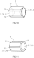
- Figure 10 is a schematic view of an exemplary embodiment of the protective element 2 similar to the one of figure 8 .
- a reinforcement part 11 is arranged within the cavity 6 of the protective element 2 to internally support two opposite ones of the fins 7.3.
- the reinforcement part 11 may be configured as a planar structure extending between the two supported fins 7.3.
- the planar structure of the reinforcement part 11 may be based on a rectangular shape with a cut-out, e.g. a circular sector, in particular a half circle, cut out respectively on two opposing sides, one facing the front wall 9 and the other facing the opening 8.
- the reinforcement part 11 is configured to provide mechanical stability without impact on the acoustic performance.
- the cut-out serves for providing the same acoustic pressure everywhere in the cavity 6.
- the cut-out does not necessarily have to be circular.
- Figure 11 is a schematic view of an exemplary embodiment of the protective element 2 similar to the one of figure 8 .
- a frontside of the protective element 2 may be provided with a rounded structure 12 to prevent irritations in case of contact with the ear canal skin.
- the rounded structure 12 may be arranged circumferentially around a perimeter of the front wall 9.
- Figure 12 is a schematic view of an exemplary embodiment of the protective element 2 having an alternative shape with a cross section of membrane 7 approximating a polygon with corners formed by thicker portions 7.3 and edges comprising thinner portions 7.4.
- the protective element 2 of figure 12 has a four lobe cross section approximating a rhombus, wherein the diameter across two of the opposing corners is greater than the diameter across the two other opposing corners.
- the edges between the corners may be slightly concave.
- the front wall 9 or front surface and the lateral wall 10 adjacent the front wall 9 are thinner portions 7.1.
- One or more stiffeners 7.3 e.g. fins 7.3, may be arranged along the lateral wall 10 and extend in parallel to a longitudinal axis L. In particular, the fins 7.3 form the corners of the four lobe cross section.
- Figure 13 is a schematic view of an exemplary embodiment of the protective element 2, e.g. similar to the one of figure 8 with an additional dome 13, e.g. for sealing against the ear canal of the user. This may be particularly useful for RIC (receiver in the canal) type hearing aids.
- the dome 13 may be integrally formed with the protective element 2.
- the dome 13 may be attached to the protective element 2 at the thicker portion 7.2 of the lateral wall 10 near the opening 8, in particular adjacent the thinner portion 7.1 of the lateral wall 10.
- Figure 14 is a schematic view of an exemplary embodiment of the protective element 2, e.g. similar to the one of figure 13 .
- a further dome 14 is arranged on the protective element 2, e.g. at the frontside of the protective element 2.
- the further dome 14 should be an open one to maintain the desired functionality.
- An open dome is a dome with a relatively large acoustically open cross-section. I.e. a large amount of direct sound enters the residual ear canal.
- the further dome 14 may be provided with one or more venting channels.
- the membrane 7 comprises a plurality of thinner portions 7.1, 7.4 angled relative to one another, in particular at an angle smaller than 180°.
- the thinner portions 7.1, 7.4 may be associated with a respective virtual plane extending through a perimeter of the thinner portion 7.1, 7.4, wherein respective normal vectors of the planes are angled relative to one another.
- Each of the thinner portions 7.1, 7.4 can thus be configured to vibrate in a different direction, e.g., in the direction of the normal vector, in order to transmit sound.
- an effective area of the membrane 7, which is predominantly configured for sound transmission can be effectively increased, e.g., within a restricted space such as inside an ear canal, for instance as compared to a single flat-shaped membrane.
- the membrane 7 may include at least part of the thinner portions 7.1, 7.4 in a polyhedric arrangement.
- An angle at which the thinner portions 7.1, 7.4 are angled relative to one another may be defined as an angle in between the respective virtual planes extending through the perimeter of the thinner portions 7.1, 7.4.
- the front wall 9 at a front end 23 of the membrane 7 is formed by the thinner portion 7.1.
- the front end 23 is opposing a rear end 24 of the membrane 7 at which the opening 8 is provided.
- the lateral wall 10 extends between the front wall 9 at the front end and the opening 8 at the rear end 24.
- the lateral wall 10 comprises a plurality of the thinner portions 7.4 surrounding the cavity 6, e.g., as illustrated, four thinner portions 7.4.
- the front wall 9 and the lateral wall 10 comprise an inner surface delimiting the cavity 6 and an outer surface opposing the inner surface.
- the outer surface of the lateral wall 10 may define a lateral area of the membrane 7.
- the outer surface of the front wall 9 may define a bottom of the membrane 7.
- the membrane 7 may have a cup-like or beaker-like shape with a bottom provided at the front wall 9 and a lateral area provided at the lateral wall 10.
- a central axis 22 extends through the cavity 6 surrounded by the lateral wall 10 between the front end 23 of the membrane 7, at which the front wall 9 is provided, and a rear end 24 of the membrane 7, at which the opening 8 is provided, in particular between a center of the opening 8 and a center of the front wall 9.
- Cutting plane XVI extends through the central axis 22.
- the central axis 22 is normal to cutting plane XVII.
- the lateral wall 10 further comprises thicker portions 7.2, 7.3. At least part of the thicker portions 7.2, 7.3 protrude from at least part of the thinner portions 7.4 at the inner surface of the lateral wall 10. In other examples, as described above, lateral wall 10 may also comprise thicker portions 7.2, 7.3 protruding from at least part of the thinner portions 7.4 at the outer surface of the lateral wall 10.
- the thicker portion 7.2 of the lateral wall 10 extends around a circumference of the lateral wall 10 and leads to the opening 8 at the rear end 24.
- the membrane 7 can thus be configured to be attached to the transducer 1 or sound tube 3 at the opening 8 by means of the thicker portion 7.2.
- the dome 13, which is integrally formed with the membrane 7, is attached to the thicker portion 7.2 at a distance from the rear end 24.
- Figure 22 is a schematic view of a shell 15 or housing of an earpiece configured to be inserted into an ear of a user, similar to the one of figure 21 . While in figure 21 the second part 15.2 comprises a dome shape 18 for radiating sound partially in touch with the ear canal wall 19, the dome shape 18 for radiating sound in figure 22 extends from the thicker portion 7.2 so as to be radially spaced from the ear canal wall 19 thus providing an improved radiating surface area.
- Figure 23 is a schematic view of a medial end of an exemplary embodiment of the protective element 2.
- Figure 24 is a schematic cross sectional view of the protective element 2 of figure 23 .
- the protective element 2 comprises an inversion 20 in the bottom 9 or front end, thus increasing the radiation surface area and the bending stiffness.
- Figure 25 is a variant of the embodiment of figure 23 , in which a vent 21 is integrated into the protective element 2, wherein a channel of the vent 21 opens out into the inversion 20.
- the 3D-shaped protective element 2 may be generated by using several different components, e.g. a stiff (metal and/or polymer) housing and multiple acoustically active (e.g. flat) membranes. It may also be possible to integrate the 3D-shaped protective element 2 in a dome 13 or in other receiver housing components.
- a stiff (metal and/or polymer) housing and multiple acoustically active (e.g. flat) membranes.
- acoustically active membranes e.g. flat
Landscapes
- Engineering & Computer Science (AREA)
- Physics & Mathematics (AREA)
- Acoustics & Sound (AREA)
- Signal Processing (AREA)
- Health & Medical Sciences (AREA)
- General Health & Medical Sciences (AREA)
- Neurosurgery (AREA)
- Otolaryngology (AREA)
- Manufacturing & Machinery (AREA)
- Headphones And Earphones (AREA)
- Diaphragms For Electromechanical Transducers (AREA)
- Obtaining Desirable Characteristics In Audible-Bandwidth Transducers (AREA)
Claims (13)
- Schutzelement (2), gestaltet zur Verbindung mit einem elektroakustischen Wandler (1) oder einem Schallschlauch (3), die in einem Hörgerät enthalten sind, wobei das Schutzelement (2) eine 3D-förmige Membran (7) umfasst, die einen Hohlraum (6) mit einer Öffnung (8) umschließt, an der die Membran (7) zur Verbindung mit dem Wandler (1) oder dem Schallschlauch (3) konfiguriert ist, wobei die Membran (7) einen oder mehrere dünnere (7.1, 7.4) Abschnitte aufweist, die dazu konfiguriert sind, Schall zu übertragen, und einen oder mehrere dickere Abschnitte (7.2, 7.3), an denen die Steifigkeit der Membran (7) größer ist als an dem einen oder den mehreren dünneren Abschnitten (7.1, 7.4), wobei die Membran (7) eine Vorderwand (9) an einem vorderen Ende aufweist, das einem hinteren Ende gegenüberliegt, an dem die Öffnung (8) bereitgestellt ist, und eine Seitenwand (10), die zwischen der Vorderwand (9) und der Öffnung (8) verläuft, wobei die Seitenwand (10) wenigstens einen der dickeren Abschnitte (7.2, 7.3) und einen oder mehrere der dünneren Abschnitte (7.1, 7.4) umfasst, wobei einer oder mehrere der dickeren Abschnitte (7.2, 7.3) aus dem einen oder den mehreren dünneren Abschnitten (7.1, 7.4) an einem Eckenbereich der Seitenwand (10) vorstehen, an dem der eine oder die mehreren dünneren Abschnitte (7.1, 7.4) relativ zueinander gewinkelt sind, und/oder einer oder mehrere der dickeren Abschnitte (7.2, 7.3) aus dem einen oder den mehreren dünneren Abschnitten (7.1, 7.4) an einem durchgehenden Bereich der Seitenwand (10) vorstehen, an dem der eine oder die mehreren dünneren Abschnitte (7.1, 7.4) kontinuierlich verbunden sind, wobei der eine oder die mehreren dünneren Abschnitte (7.1, 7.4) eine Dicke von weniger als 0,2 mm aufweisen.
- Schutzelement (2) nach Anspruch 1, wobei die Membran (7) wenigstens zwei dünnere Abschnitte (7.1, 7.4) aufweist, die relativ zueinander gewinkelt sind.
- Schutzelement (2) nach einem der vorstehenden Ansprüche, wobei die Membran (7) ähnlich einem Becher oder Becherglas mit einem Boden an der Vorderwand (9) und einem Seitenbereich an der Seitenwand (10) geformt ist.
- Schutzelement (2) nach einem der vorstehenden Ansprüche, wobei wenigstens einer der dickeren Abschnitte (7.2, 7.3) der Seitenwand (10) zu der Öffnung (8) führt.
- Schutzelement (2) nach einem der vorstehenden Ansprüche, wobei ein oder mehrere Versteifungselemente (7.3) durch einen oder mehrere der dickeren Abschnitte (7.2, 7.3) gebildet sind, die zwischen den dünneren Abschnitten (7.1, 7.4) an der Außenseite und/oder an der Innenseite der Membran (7) verlaufen.
- Schutzelement (2) nach einem der Ansprüche 1 bis 4 und Anspruch 5, wobei wenigstens zwei der Versteifungselemente (7.3) entlang eines Umfangs der Seitenwand (10) voneinander beabstandet sind.
- Schutzelement (2) nach einem der vorstehenden Ansprüche, wobei die Membran (7) einen Querschnitt aufweist, der näherungsweise ein Polygon ist, dessen Kanten an Ecken verbunden sind, wobei die Ecken wenigstens von einem Teil der dickeren Abschnitte (7.2, 7.3) gebildet sind und die Kanten wenigstens einen Teil der dünneren Abschnitte (7.1, 7.4) umfassen.
- Schutzelement (2) nach einem der vorstehenden Ansprüche, wobei die Membran (7) durch Spritzguss gebildet ist.
- Schutzelement (2) nach einem der vorstehenden Ansprüche, ferner umfassend ein oder mehrere Verstärkungsteile (11) aus einem anderen Material als die Membran (7) und an der Außenseite und/oder an der Innenseite der Membran (7) angeordnet.
- Schutzelement (2) nach einem der vorstehenden Ansprüche, ferner umfassend wenigstens ein Verstärkungsteil (11) aus einem anderen Material als die Membran (7) und innerhalb des Hohlraums (6) angeordnet, um die Membran (7) innenseitig zu stützen.
- Schutzelement (2) nach einem der vorstehenden Ansprüche, wobei der eine oder die mehreren dünnere Abschnitte (7.1, 7.4) eine Oberfläche der Membran (7) von wenigstens 30 mm2 darstellen.
- Schutzelement (2) nach einem der vorstehenden Ansprüche, ferner umfassend wenigstens eine Kuppel (13, 14), die zur Abdichtung gegen einen Gehörgang gestaltet ist, wobei die wenigstens eine Kuppel (13, 14) integral mit der Membran (7) gebildet ist.
- Hörgerät, umfassend einen elektroakustischen Wandler (1) und/oder einen Schallschlauch (3) und ein Schutzelement (2) nach einem der vorstehenden Ansprüche, wobei die Membran (7) mit dem elektroakustischen Wandler (1) oder dem Schallschlauch (3) verbunden ist.
Priority Applications (6)
| Application Number | Priority Date | Filing Date | Title |
|---|---|---|---|
| EP22191488.0A EP4329334B1 (de) | 2022-08-22 | 2022-08-22 | Schutzelement für einen elektroakustischen wandler eines hörgerätes oder für einen schallschlauch in einem hörgerät |
| EP25174552.7A EP4576832A3 (de) | 2022-08-22 | 2022-08-22 | Schutzelement für einen elektroakustischen wandler eines hörgerätes oder für einen schallschlauch in einem hörgerät |
| CN202310897974.3A CN117615289A (zh) | 2022-08-22 | 2023-07-20 | 用于听力装置的电声换能器或包括在听力装置中的声管的保护元件 |
| US18/233,491 US12389176B2 (en) | 2022-08-22 | 2023-08-14 | Protective element for an electroacoustic transducer of a hearing device or for a sound tube included in a hearing device |
| US18/910,219 US12231855B1 (en) | 2022-08-22 | 2024-10-09 | Protective element for an electroacoustic transducer of a hearing device or for a sound tube included in a hearing device |
| US19/220,596 US20250294301A1 (en) | 2022-08-22 | 2025-05-28 | Protective element for an electroacoustic transducer of a hearing device or for a sound tube included in a hearing device |
Applications Claiming Priority (1)
| Application Number | Priority Date | Filing Date | Title |
|---|---|---|---|
| EP22191488.0A EP4329334B1 (de) | 2022-08-22 | 2022-08-22 | Schutzelement für einen elektroakustischen wandler eines hörgerätes oder für einen schallschlauch in einem hörgerät |
Related Child Applications (2)
| Application Number | Title | Priority Date | Filing Date |
|---|---|---|---|
| EP25174552.7A Division EP4576832A3 (de) | 2022-08-22 | 2022-08-22 | Schutzelement für einen elektroakustischen wandler eines hörgerätes oder für einen schallschlauch in einem hörgerät |
| EP25174552.7A Division-Into EP4576832A3 (de) | 2022-08-22 | 2022-08-22 | Schutzelement für einen elektroakustischen wandler eines hörgerätes oder für einen schallschlauch in einem hörgerät |
Publications (3)
| Publication Number | Publication Date |
|---|---|
| EP4329334A1 EP4329334A1 (de) | 2024-02-28 |
| EP4329334C0 EP4329334C0 (de) | 2025-07-02 |
| EP4329334B1 true EP4329334B1 (de) | 2025-07-02 |
Family
ID=83005974
Family Applications (2)
| Application Number | Title | Priority Date | Filing Date |
|---|---|---|---|
| EP25174552.7A Pending EP4576832A3 (de) | 2022-08-22 | 2022-08-22 | Schutzelement für einen elektroakustischen wandler eines hörgerätes oder für einen schallschlauch in einem hörgerät |
| EP22191488.0A Active EP4329334B1 (de) | 2022-08-22 | 2022-08-22 | Schutzelement für einen elektroakustischen wandler eines hörgerätes oder für einen schallschlauch in einem hörgerät |
Family Applications Before (1)
| Application Number | Title | Priority Date | Filing Date |
|---|---|---|---|
| EP25174552.7A Pending EP4576832A3 (de) | 2022-08-22 | 2022-08-22 | Schutzelement für einen elektroakustischen wandler eines hörgerätes oder für einen schallschlauch in einem hörgerät |
Country Status (3)
| Country | Link |
|---|---|
| US (3) | US12389176B2 (de) |
| EP (2) | EP4576832A3 (de) |
| CN (1) | CN117615289A (de) |
Family Cites Families (12)
| Publication number | Priority date | Publication date | Assignee | Title |
|---|---|---|---|---|
| US4953215A (en) | 1989-10-05 | 1990-08-28 | Siemens Aktiengesellschaft | Arrangement to prevent the intrusion of foreign matter into an electro-acoustical transducer |
| DE19640796A1 (de) * | 1996-10-02 | 1998-04-16 | Siemens Audiologische Technik | Schutzvorrichtung für die Schallein- und/oder Schallaustrittsöffnung an Gehäusen oder Ohrpaßstücken von Hörhilfegeräten |
| US6473513B1 (en) | 1999-06-08 | 2002-10-29 | Insonus Medical, Inc. | Extended wear canal hearing device |
| US7664282B2 (en) | 1998-11-25 | 2010-02-16 | Insound Medical, Inc. | Sealing retainer for extended wear hearing devices |
| WO2009056167A1 (en) | 2007-10-30 | 2009-05-07 | 3Win N.V. | Body-worn wireless transducer module |
| EP2944096B1 (de) * | 2013-01-11 | 2021-08-04 | Sonova AG | Schale für eine hörvorrichtung |
| DK3025511T3 (da) | 2013-07-22 | 2020-03-23 | Sonova Ag | Høreapparat med forbedret lav frekvensrespons samt metoden for fremstillingen af sagte høreapparat |
| DK3142386T3 (da) | 2015-09-08 | 2019-07-08 | Oticon As | Tætningsørestykke |
| WO2018228988A1 (en) | 2017-06-16 | 2018-12-20 | Widex A/S | Flexible ear piece for a hearing aid |
| US11228851B2 (en) | 2017-11-28 | 2022-01-18 | Sonova Ag | Cerumen protection plug |
| DE102018107195B3 (de) | 2018-02-05 | 2019-02-14 | Paul Gregor Junke | Universal Silikon-Softadapter für Hörgeräte |
| CN112823533B (zh) * | 2018-10-03 | 2022-06-21 | 纱帝股份公司 | 用于音频设备的透声保护器及音频设备 |
-
2022
- 2022-08-22 EP EP25174552.7A patent/EP4576832A3/de active Pending
- 2022-08-22 EP EP22191488.0A patent/EP4329334B1/de active Active
-
2023
- 2023-07-20 CN CN202310897974.3A patent/CN117615289A/zh active Pending
- 2023-08-14 US US18/233,491 patent/US12389176B2/en active Active
-
2024
- 2024-10-09 US US18/910,219 patent/US12231855B1/en active Active
-
2025
- 2025-05-28 US US19/220,596 patent/US20250294301A1/en active Pending
Also Published As
| Publication number | Publication date |
|---|---|
| US12389176B2 (en) | 2025-08-12 |
| US20240064481A1 (en) | 2024-02-22 |
| EP4576832A3 (de) | 2025-09-24 |
| US12231855B1 (en) | 2025-02-18 |
| EP4329334A1 (de) | 2024-02-28 |
| US20250294301A1 (en) | 2025-09-18 |
| US20250039619A1 (en) | 2025-01-30 |
| EP4576832A2 (de) | 2025-06-25 |
| CN117615289A (zh) | 2024-02-27 |
| EP4329334C0 (de) | 2025-07-02 |
Similar Documents
| Publication | Publication Date | Title |
|---|---|---|
| US7113611B2 (en) | Disposable modular hearing aid | |
| JP4839016B2 (ja) | 補聴器用柔軟性耳当て | |
| US7403629B1 (en) | Disposable modular hearing aid | |
| US20070071265A1 (en) | Disposable modular hearing aid | |
| CN107950034B (zh) | 入耳式耳机的降噪 | |
| JP5150798B1 (ja) | 補聴器用イヤプラグおよび補聴器 | |
| EP2443842B1 (de) | Hörgerät mit ersetzbarer einführungsabdeckung | |
| EP2076064B1 (de) | Hörvorrichtung mit Hörgeräte-Otoplastik und Ausgangsmodul | |
| US12413919B2 (en) | Wax protection for in-canal hearing device | |
| EP3334179B1 (de) | Hörgerät mit einer erweiterten kuppel | |
| EP1175811B1 (de) | Wegwerfbares modulares hörhilfegerät | |
| EP4329334B1 (de) | Schutzelement für einen elektroakustischen wandler eines hörgerätes oder für einen schallschlauch in einem hörgerät | |
| US11330382B2 (en) | Acoustical protector for audio devices and audio device provided with said protector | |
| US11178497B2 (en) | In-ear receiver | |
| US20250211921A1 (en) | Hearing device comprising a mechanical element for sound transmission | |
| WO2001069973A2 (en) | Disposable modular hearing aid | |
| US20250287162A1 (en) | Hearing device comprising a mechanical element for sound transmission | |
| CN114640915A (zh) | 入耳式声学装置 | |
| CN119545240A (zh) | 用于听力装置的耳罩 | |
| CN116896702A (zh) | 听力装置 | |
| HK1171891B (en) | Earphones |
Legal Events
| Date | Code | Title | Description |
|---|---|---|---|
| PUAI | Public reference made under article 153(3) epc to a published international application that has entered the european phase |
Free format text: ORIGINAL CODE: 0009012 |
|
| STAA | Information on the status of an ep patent application or granted ep patent |
Free format text: STATUS: THE APPLICATION HAS BEEN PUBLISHED |
|
| AK | Designated contracting states |
Kind code of ref document: A1 Designated state(s): AL AT BE BG CH CY CZ DE DK EE ES FI FR GB GR HR HU IE IS IT LI LT LU LV MC MK MT NL NO PL PT RO RS SE SI SK SM TR |
|
| STAA | Information on the status of an ep patent application or granted ep patent |
Free format text: STATUS: REQUEST FOR EXAMINATION WAS MADE |
|
| 17P | Request for examination filed |
Effective date: 20240522 |
|
| RBV | Designated contracting states (corrected) |
Designated state(s): AL AT BE BG CH CY CZ DE DK EE ES FI FR GB GR HR HU IE IS IT LI LT LU LV MC MK MT NL NO PL PT RO RS SE SI SK SM TR |
|
| STAA | Information on the status of an ep patent application or granted ep patent |
Free format text: STATUS: EXAMINATION IS IN PROGRESS |
|
| 17Q | First examination report despatched |
Effective date: 20240724 |
|
| GRAP | Despatch of communication of intention to grant a patent |
Free format text: ORIGINAL CODE: EPIDOSNIGR1 |
|
| STAA | Information on the status of an ep patent application or granted ep patent |
Free format text: STATUS: GRANT OF PATENT IS INTENDED |
|
| INTG | Intention to grant announced |
Effective date: 20250220 |
|
| GRAS | Grant fee paid |
Free format text: ORIGINAL CODE: EPIDOSNIGR3 |
|
| GRAA | (expected) grant |
Free format text: ORIGINAL CODE: 0009210 |
|
| STAA | Information on the status of an ep patent application or granted ep patent |
Free format text: STATUS: THE PATENT HAS BEEN GRANTED |
|
| AK | Designated contracting states |
Kind code of ref document: B1 Designated state(s): AL AT BE BG CH CY CZ DE DK EE ES FI FR GB GR HR HU IE IS IT LI LT LU LV MC MK MT NL NO PL PT RO RS SE SI SK SM TR |
|
| REG | Reference to a national code |
Ref country code: GB Ref legal event code: FG4D |
|
| REG | Reference to a national code |
Ref country code: CH Ref legal event code: EP |
|
| REG | Reference to a national code |
Ref country code: IE Ref legal event code: FG4D |
|
| U01 | Request for unitary effect filed |
Effective date: 20250708 |
|
| U07 | Unitary effect registered |
Designated state(s): AT BE BG DE DK EE FI FR IT LT LU LV MT NL PT RO SE SI Effective date: 20250711 |
|
| U20 | Renewal fee for the european patent with unitary effect paid |
Year of fee payment: 4 Effective date: 20250827 |
|
| PG25 | Lapsed in a contracting state [announced via postgrant information from national office to epo] |
Ref country code: IS Free format text: LAPSE BECAUSE OF FAILURE TO SUBMIT A TRANSLATION OF THE DESCRIPTION OR TO PAY THE FEE WITHIN THE PRESCRIBED TIME-LIMIT Effective date: 20251102 |
|
| PG25 | Lapsed in a contracting state [announced via postgrant information from national office to epo] |
Ref country code: NO Free format text: LAPSE BECAUSE OF FAILURE TO SUBMIT A TRANSLATION OF THE DESCRIPTION OR TO PAY THE FEE WITHIN THE PRESCRIBED TIME-LIMIT Effective date: 20251002 |
|
| PG25 | Lapsed in a contracting state [announced via postgrant information from national office to epo] |
Ref country code: HR Free format text: LAPSE BECAUSE OF FAILURE TO SUBMIT A TRANSLATION OF THE DESCRIPTION OR TO PAY THE FEE WITHIN THE PRESCRIBED TIME-LIMIT Effective date: 20250702 |
|
| PG25 | Lapsed in a contracting state [announced via postgrant information from national office to epo] |
Ref country code: GR Free format text: LAPSE BECAUSE OF FAILURE TO SUBMIT A TRANSLATION OF THE DESCRIPTION OR TO PAY THE FEE WITHIN THE PRESCRIBED TIME-LIMIT Effective date: 20251003 |
|
| PG25 | Lapsed in a contracting state [announced via postgrant information from national office to epo] |
Ref country code: CZ Free format text: LAPSE BECAUSE OF FAILURE TO SUBMIT A TRANSLATION OF THE DESCRIPTION OR TO PAY THE FEE WITHIN THE PRESCRIBED TIME-LIMIT Effective date: 20250702 |
|
| PG25 | Lapsed in a contracting state [announced via postgrant information from national office to epo] |
Ref country code: PL Free format text: LAPSE BECAUSE OF FAILURE TO SUBMIT A TRANSLATION OF THE DESCRIPTION OR TO PAY THE FEE WITHIN THE PRESCRIBED TIME-LIMIT Effective date: 20250702 |
|
| PG25 | Lapsed in a contracting state [announced via postgrant information from national office to epo] |
Ref country code: RS Free format text: LAPSE BECAUSE OF FAILURE TO SUBMIT A TRANSLATION OF THE DESCRIPTION OR TO PAY THE FEE WITHIN THE PRESCRIBED TIME-LIMIT Effective date: 20251002 |
|
| PG25 | Lapsed in a contracting state [announced via postgrant information from national office to epo] |
Ref country code: ES Free format text: LAPSE BECAUSE OF FAILURE TO SUBMIT A TRANSLATION OF THE DESCRIPTION OR TO PAY THE FEE WITHIN THE PRESCRIBED TIME-LIMIT Effective date: 20250702 |