EP4576528A1 - Power converter - Google Patents
Power converter Download PDFInfo
- Publication number
- EP4576528A1 EP4576528A1 EP24215788.1A EP24215788A EP4576528A1 EP 4576528 A1 EP4576528 A1 EP 4576528A1 EP 24215788 A EP24215788 A EP 24215788A EP 4576528 A1 EP4576528 A1 EP 4576528A1
- Authority
- EP
- European Patent Office
- Prior art keywords
- diode
- leg
- input
- switching element
- output
- Prior art date
- Legal status (The legal status is an assumption and is not a legal conclusion. Google has not performed a legal analysis and makes no representation as to the accuracy of the status listed.)
- Pending
Links
Images






Classifications
-
- H—ELECTRICITY
- H02—GENERATION; CONVERSION OR DISTRIBUTION OF ELECTRIC POWER
- H02M—APPARATUS FOR CONVERSION BETWEEN AC AND AC, BETWEEN AC AND DC, OR BETWEEN DC AND DC, AND FOR USE WITH MAINS OR SIMILAR POWER SUPPLY SYSTEMS; CONVERSION OF DC OR AC INPUT POWER INTO SURGE OUTPUT POWER; CONTROL OR REGULATION THEREOF
- H02M1/00—Details of apparatus for conversion
- H02M1/0083—Converters characterised by their input or output configuration
- H02M1/0085—Partially controlled bridges
-
- H—ELECTRICITY
- H02—GENERATION; CONVERSION OR DISTRIBUTION OF ELECTRIC POWER
- H02M—APPARATUS FOR CONVERSION BETWEEN AC AND AC, BETWEEN AC AND DC, OR BETWEEN DC AND DC, AND FOR USE WITH MAINS OR SIMILAR POWER SUPPLY SYSTEMS; CONVERSION OF DC OR AC INPUT POWER INTO SURGE OUTPUT POWER; CONTROL OR REGULATION THEREOF
- H02M1/00—Details of apparatus for conversion
- H02M1/42—Circuits or arrangements for compensating for or adjusting power factor in converters or inverters
- H02M1/4208—Arrangements for improving power factor of AC input
-
- H—ELECTRICITY
- H02—GENERATION; CONVERSION OR DISTRIBUTION OF ELECTRIC POWER
- H02M—APPARATUS FOR CONVERSION BETWEEN AC AND AC, BETWEEN AC AND DC, OR BETWEEN DC AND DC, AND FOR USE WITH MAINS OR SIMILAR POWER SUPPLY SYSTEMS; CONVERSION OF DC OR AC INPUT POWER INTO SURGE OUTPUT POWER; CONTROL OR REGULATION THEREOF
- H02M1/00—Details of apparatus for conversion
- H02M1/0003—Details of control, feedback or regulation circuits
- H02M1/0025—Arrangements for modifying reference values, feedback values or error values in the control loop of a converter
-
- H—ELECTRICITY
- H02—GENERATION; CONVERSION OR DISTRIBUTION OF ELECTRIC POWER
- H02M—APPARATUS FOR CONVERSION BETWEEN AC AND AC, BETWEEN AC AND DC, OR BETWEEN DC AND DC, AND FOR USE WITH MAINS OR SIMILAR POWER SUPPLY SYSTEMS; CONVERSION OF DC OR AC INPUT POWER INTO SURGE OUTPUT POWER; CONTROL OR REGULATION THEREOF
- H02M1/00—Details of apparatus for conversion
- H02M1/08—Circuits specially adapted for the generation of control voltages for semiconductor devices incorporated in static converters
- H02M1/088—Circuits specially adapted for the generation of control voltages for semiconductor devices incorporated in static converters for the simultaneous control of series or parallel connected semiconductor devices
-
- H—ELECTRICITY
- H02—GENERATION; CONVERSION OR DISTRIBUTION OF ELECTRIC POWER
- H02M—APPARATUS FOR CONVERSION BETWEEN AC AND AC, BETWEEN AC AND DC, OR BETWEEN DC AND DC, AND FOR USE WITH MAINS OR SIMILAR POWER SUPPLY SYSTEMS; CONVERSION OF DC OR AC INPUT POWER INTO SURGE OUTPUT POWER; CONTROL OR REGULATION THEREOF
- H02M1/00—Details of apparatus for conversion
- H02M1/42—Circuits or arrangements for compensating for or adjusting power factor in converters or inverters
- H02M1/4208—Arrangements for improving power factor of AC input
- H02M1/4233—Arrangements for improving power factor of AC input using a bridge converter comprising active switches
-
- H—ELECTRICITY
- H02—GENERATION; CONVERSION OR DISTRIBUTION OF ELECTRIC POWER
- H02M—APPARATUS FOR CONVERSION BETWEEN AC AND AC, BETWEEN AC AND DC, OR BETWEEN DC AND DC, AND FOR USE WITH MAINS OR SIMILAR POWER SUPPLY SYSTEMS; CONVERSION OF DC OR AC INPUT POWER INTO SURGE OUTPUT POWER; CONTROL OR REGULATION THEREOF
- H02M7/00—Conversion of AC power input into DC power output; Conversion of DC power input into AC power output
- H02M7/02—Conversion of AC power input into DC power output without possibility of reversal
- H02M7/04—Conversion of AC power input into DC power output without possibility of reversal by static converters
- H02M7/12—Conversion of AC power input into DC power output without possibility of reversal by static converters using discharge tubes with control electrode or semiconductor devices with control electrode
- H02M7/21—Conversion of AC power input into DC power output without possibility of reversal by static converters using discharge tubes with control electrode or semiconductor devices with control electrode using devices of a triode or transistor type requiring continuous application of a control signal
- H02M7/217—Conversion of AC power input into DC power output without possibility of reversal by static converters using discharge tubes with control electrode or semiconductor devices with control electrode using devices of a triode or transistor type requiring continuous application of a control signal using semiconductor devices only
-
- Y—GENERAL TAGGING OF NEW TECHNOLOGICAL DEVELOPMENTS; GENERAL TAGGING OF CROSS-SECTIONAL TECHNOLOGIES SPANNING OVER SEVERAL SECTIONS OF THE IPC; TECHNICAL SUBJECTS COVERED BY FORMER USPC CROSS-REFERENCE ART COLLECTIONS [XRACs] AND DIGESTS
- Y02—TECHNOLOGIES OR APPLICATIONS FOR MITIGATION OR ADAPTATION AGAINST CLIMATE CHANGE
- Y02B—CLIMATE CHANGE MITIGATION TECHNOLOGIES RELATED TO BUILDINGS, e.g. HOUSING, HOUSE APPLIANCES OR RELATED END-USER APPLICATIONS
- Y02B70/00—Technologies for an efficient end-user side electric power management and consumption
- Y02B70/10—Technologies improving the efficiency by using switched-mode power supplies [SMPS], i.e. efficient power electronics conversion e.g. power factor correction or reduction of losses in power supplies or efficient standby modes
Definitions
- PFC circuits power factor correction circuits
- JP2021-069253A input current waveform
- PFC circuits power factor correction circuits
- One type of PFC circuits that is widely used is a bridgeless PFC circuit in which diodes of a full-wave rectifier circuit with high loss is replaced with a switching element (MOSFET) to improve efficiency.
- MOSFET switching element
- the AC/DC converter equipped with such a bridgeless PFC circuit generally adopts an average current mode control since there is no need to apply slope compensation in the control method.
- the average current mode control has a disadvantage in which a reactor becomes large in size since the current control becomes unstable when the capacity of the reactor is small.
- the switching frequency is basically the same as the control frequency, it is also disadvantageous in that it is difficult to increase the switching frequency.
- JP2022-129664A discloses a bridgeless PFC circuit, in which every time a polarity of input voltage changes between positive and negative, the polarity is determined and two MOSFETs (Nch) are controlled to switch between an active switch and a synchronous rectification switch.
- Nch MOSFETs
- the average current mode control is adoption of a peak current mode control.
- the pulsation of the reactor current can be made larger than that of the average current mode control, and the current control is relatively stable even if the capacity of the reactor is small. Therefore, the reactor can be made smaller in size.
- the slope compensation is necessary to ensure stable operation.
- the present disclosure discloses a technique which enables an AC/DC converter provided with a bridgeless PFC circuit to perform a peak current mode control using commercially-available slope compensation function components.
- the present disclosure relates to a power converter configured to convert AC input voltage into DC output voltage, including a converter mechanism having a bridgeless PFC circuit and a controller which controls the converter mechanism, that is, an AC/DC converter.
- the bridgeless PFC circuit includes a pair of input-side wirings which inputs the AC input voltage, a pair of output-side wirings which outputs the DC output voltage, a capacitor connected to the pair of input-side wirings, a reactor disposed in at least one of the pair of input-side wirings at a position on an output side of a connecting position with the capacitor, and a first switching element and a second switching element each disposed between one of the pair of input-side wirings and one of the pair of output-side wirings, and on which a switching operation is performed by the controller.
- the controller includes a peak current control unit which executes a peak current mode control by using a first slope compensation circuit corresponding to a positive polarity of the AC input voltage, and a second slope compensation circuit corresponding to a negative polarity of the AC input voltage.
- the second slope compensation circuit has an inverting circuit which inverts the polarity of the AC input voltage, and is structured using a same slope compensation circuit as the first slope compensation circuit.
- the second slope compensation circuit corresponding to the negative polarity includes the inverting circuit which inverts the polarity of the input voltage, and is structured using the same slope compensation circuit as the first slope compensation circuit.
- the peak current mode control can be performed using commercially-available slope compensation function components, making it possible to reduce the size of the reactor and providing an AC/DC converter which is inexpensive and high in performance.
- the peak current mode control can be performed with a relatively simple circuit.
- the controller may further include an AC current control unit which receives the second input current command value and outputs a third input current command value corresponding to an instantaneous value of the input current flowing in the input-side wirings at the connecting positions with the capacitor.
- the peak current command value received by the peak current control unit may be set by adding the current correction amount to the third input current command value.
- the bridgeless PFC circuit may include various configurations.
- the bridgeless PFC circuit may further include a first diode and a second diode, and a first leg and a second leg connected in parallel to each other between the pair of output-side wirings.
- the first leg may be provided with the first switching element and the first diode in series so that the current flows in directions away from each other, and the second leg may be provided with the second switching element and the second diode symmetrically to the first switching element and the first diode.
- An output end of one of the input-side wirings may be connected to the first leg between the first switching element and the first diode, and an output end of the other one of the input-side wirings may be connected to the second leg between the second switching element and the second diode.
- An output end of one of the input-side wirings may be connected to the first leg between the first diode and the second diode, and an output end of the other one of the input-side wirings may be connected to the second leg between the third diode and the fourth diode.
- Fig. 1 illustrates the vehicle 1 and a commercial power source 2 during charging.
- the commercial power source 2 outputs high alternating current (AC) voltages such as 100V and 200V.
- the battery 4 is charged by connecting the commercial power source 2 to the vehicle 1 by a cable.
- the charging system 3 interposes between the battery 4 and the commercial power source 2, and converts the AC voltage into direct current DC voltage compatible with the battery 4.
- the DC/DC converter 5 converts DC voltage into different DC voltage.
- the DC/DC converter 5 converts the DC voltage (V dc ) converted by the AC/DC converter 6 into given DC voltage (V dc' ) and outputs it to the battery 4 side.
- the AC/DC converter 6 includes a converter mechanism 13 having a current sensor 10, an input voltage sensor 11, an output voltage sensor 12, and a bridgeless power factor correction (PFC) circuit 20, and a controller 14 which controls the converter mechanism 13.
- a converter mechanism 13 having a current sensor 10, an input voltage sensor 11, an output voltage sensor 12, and a bridgeless power factor correction (PFC) circuit 20, and a controller 14 which controls the converter mechanism 13.
- PFC power factor correction
- the current sensor 10 is a Hall element type sensor and is installed at a given position of an input-side wiring 21, as described below.
- the current sensor 10 directly measures input current (reactor current i inv ) flowing through a reactor 24 and outputs it to the controller 14.
- the input voltage sensor 11 is also installed at a given position of the input-side wiring 21, and directly measures the AC input voltage einv inputted to the AC/DC converter 6 and outputs it to the controller 14.
- the output voltage sensor 12 is installed at a given position of an output-side wiring 22 and directly measures the DC output voltage V dc outputted from the AC/DC converter 6 and outputs it to the controller 14.
- the controller 14 Based on these measurement values, the controller 14 performs an ON/OFF control by outputting drive voltage to two switching elements S1 and S2 of the bridgeless PFC circuit 20. That is, the controller 14 switches the switching elements S1 and S2 between a conducting state (ON) and a non-conducting state (OFF) at a given timing.
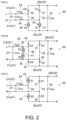
- Fig. 2 illustrates types A to C of the bridgeless PFC circuit 20 applicable to the AC/DC converter 6. All of these types of bridgeless PFC circuits 20 have a common basic circuit.
- the pair of input-side wirings 21 is disposed on the side of the commercial power source 2, and the AC input voltage e inv is inputted to input terminals thereof.
- the pair of output-side wirings 22 is disposed on the side of the battery 4, and the DC output voltage V dc is outputted from output terminals thereof.
- the input-side capacitor 23 is connected between the pair of input-side wirings 21 near the input terminals.
- the reactor 24 is disposed at least in one of the input-side wiring 21 at a position on the output side from a connecting point of the input-side capacitor 23. In this embodiment, the reactor 24 is disposed in the L input-side wiring 21b. While the first switching element 25 and the second switching element 26 have different positional arrangements depending on the type, they are disposed between the input-side wirings 21 and the output-side wirings 22.
- the type A bridgeless PFC circuit 20 in addition to the basic circuit described above, it further includes a first diode 31 (D1), a second diode 32 (D2), a first leg 33, a second leg 34, an output-side capacitor 35 (C dc ), and a second reactor 36.
- the second reactor 36 is arranged in the N input-side wiring 21a symmetrically to the reactor 24. Note that the second reactor 36 may be omitted.
- the first switching element 25 and the first diode 31 are arranged in this order from the N output-side wiring 22a side to the P output-side wiring 22b side.
- the first switching element 25 is arranged so that the current flows from the P output-side wiring 22b side to the N output-side wiring 22a side
- the first diode 31 is arranged so that the current flows from the N output-side wiring 22a side to the P output-side wiring 22b side.
- the second switching element 26 and the second diode 32 are arranged in the second leg 34 symmetrically to the first switching element 25 and the first diode 31.
- the second switching element 26 and the second diode 32 are arranged in this order from the N output-side wiring 22a side to the P output-side wiring 22b side.
- the second switching element 26 is arranged so that the current flows from the P output-side wiring 22b side to the N output-side wiring 22a side
- the second diode 32 is arranged so that the current flows from the N output-side wiring 22a side to the P output-side wiring 22b side.
- the type B bridgeless PFC circuit 20 in addition to the basic circuit described above, it further includes a first diode 41, a second diode 42, a third diode 43 (D3), a fourth diode 44 (D4), a first leg 45, a second leg 46, a third leg 47, and an output-side capacitor 48.
- the second diode 42 and the first diode 41 are arranged in this order from the N output-side wiring 22a side to the P output-side wiring 22b side. Further, the first diode 41 and the second diode 42 are arranged so that the current flows from the N output-side wiring 22a side to the P output-side wiring 22b side.
- the third diode 43 and the fourth diode 44 are arranged in the second leg 46 symmetrically to the first diode 41 and the second diode 42. Specifically, the fourth diode 44 and the third diode 43 are arranged in this order from the N output-side wiring 22a side to the P output-side wiring 22b side. The third diode 43 and the fourth diode 44 are arranged so that the current flows from the N output-side wiring 22a side to the P output-side wiring 22b side.
- the first switching element 25 and the second switching element 26 are arranged in series in the third leg 47 to have opposing conductive directions to each other. Specifically, the second switching element 26 and the first switching element 25 are arranged in this order from the N input-side wiring 21a side to the L input-side wiring 21b side.
- the second switching element 26 in the ON state is arranged so that the current flows from the N input-side wiring 21a side to the L input-side wiring 21b side
- the first switching element 25 in the ON state is arranged so that the current flows from the L input-side wiring 21b side to the N input-side wiring 21a side.
- the output-side capacitor 55 is connected between the pair of output-side wirings 22a and 22b near output terminals thereof.
- the first leg 53 and the second leg 54 are connected in parallel to each other between the pair of output-side wirings 22a and 22b on the input side of the output-side capacitor 55.
- the first diode 51 and the second diode 52 are arranged in series in the first leg 53 to have the same conductive direction. Specifically, the second diode 52 and the first diode 51 are arranged in this order from the N output-side wiring 22a side to the P output-side wiring 22b side. Both of the first diode 51 and the second diode 52 are arranged so that the current flows from the N output-side wiring 22a side to the P output-side wiring 22b side.
- the first switching element 25 and the second switching element 26 are arranged in series in the second leg 54 so that the current flows opposite from that in the first diode 51 and the second diode 52.
- the second switching element 26 and the first switching element 25 are arranged in this order from the N output-side wiring 22a side to the P output-side wiring 22b side.
- both of the first switching element 25 and the second switching element 26 are arranged so that the current flows from the P output-side wiring 22b side to the N output-side wiring 22a side in the ON state.
- a reference character R illustrated in Fig. 3 indicates a load resistance on the side of the battery 4.
- the current sensor 10, the input voltage sensor 11, and the output voltage sensor 12 are also illustrated in part (a) of Fig. 3 in a simplified manner. Note that although the type B and C bridgeless PFC circuits 20 have different current paths as they have different circuit structures, since the control targets are the same first switching element S1 and second switching element S2, the explanation of the operations thereof is omitted.
- parts (a) and (b) indicate an operation when the polarity of the input voltage e inv is positive (during a positive half cycle).
- parts (c) and (d) illustrate an operation when the polarity of the input voltage e inv is negative (during a negative half cycle).
- the operations of parts (a) to (d) are repeated according to the polarity of the input voltage ei nv .
- the input current i ac flowing in from the L input-side wiring 21b flows through a current path comprised of the intermediate position of the second leg 34, the second diode 52, the P output-side wiring 22b, the load resistor R, the N output-side wiring 22a, the first switching element S1 (the flyback diode 27), the intermediate position of the first leg 33, and the N input-side wiring 21a.
- the input current i ac flows to the battery 4 side.
- the input current i ac flows in from the N input-side wiring 21a. Then, as indicated by a dashed arrow Y3, the input current i ac flows through a current path comprised of the intermediate position of the first leg 33, the first switching element S1, the N output-side wiring 22a, the second switching element S2 (the flyback diode 27), the intermediate position of the second leg 34, and the L input-side wiring 21b. In other words, the input current i ac does not flow to the battery 4 side.
- the input current i ac flowing in from the N input-side wiring 21a flows through a current path comprised of the intermediate position of the first leg 33, the first diode D1, the P output-side wiring 22b, the load resistor R, the N output-side wiring 22a, the second switching element S2 (the flyback diode 27), the intermediate position of the second leg 34, and the L input-side wiring 21b. That is, the input current i ac flows to the battery 4 side.
- the controller 14 outputs required output voltage command V* dc by switching between the first switching element S1 and the second switching element S2.
- V* dc required output voltage command
- FIG. 4 One example of a block diagram of the control circuit provided to the AC current controller 14 for this is illustrated in Fig. 4 .
- the AC current controller 14 is followed by the AC current command I*inv (peak-value) of DC voltage control unit 60 which controls the AC current so that a given level of the output voltage command V* dc is outputted in response to an output request of the output voltage V dc , and a peak current control unit 80 which controls an ON/OFF timing of the first switching element S1 and the second switching element S2.
- the controller 14 is also configured with a phase locked loop 61, a multiplier 62, and an adder 63.
- the DC voltage control unit 60 receives a command value V dc * of the output voltage and an actual value V dc of the output voltage measured by the output voltage sensor 12. Further, the DC voltage control unit 60 outputs a command value (a first input current command value I inv *) corresponding to a maximum value of the input current (a reactor current i inv ) flowing in the input-side wiring 21 on the output side of a connecting position of the input-side capacitor 23, that is, the reactor 24.
- the actual value V dc of the output voltage is used as a feedback value, and the DC voltage control unit 60 controls the first input current command value I inv * so that the actual value V dc coincides with the command value V dc *.
- the first input current command value I inv * is inputted to the multiplier 62, where it is converted into a command value (a second input current command value i inv *) corresponding to an instantaneous value based on the phase of the input voltage ei nv .
- the actual value of the input voltage e inv measured by the input voltage sensor 11 is inputted to the phase synchronization circuit 61.
- the phase angle ⁇ inv of the input voltage e inv is calculated based on the actual value, and a given signal (a phase signal, sin( ⁇ inv )) is outputted from the phase synchronization circuit 61 based on the phase angle ⁇ inv and received by the multiplier 62.
- the multiplier 62 the first input current command value I inv * is multiplied by the phase signal sin( ⁇ inv ) to calculate the second input current command value i inv *, and this value is outputted.
- the second input current command value i inv * is inputted to the adder 63, where a given current correction amount ⁇ i inv is added.
- a peak current command value i inv *.p is set as an instantaneous value to be received by the peak current control unit 80.
- the current correction amount ⁇ i inv is an estimated value of a pulsation component of the reactor current, and is calculated by Equation (1) illustrated in Fig. 4 .
- Equation (1) to (3) “L inv” indicates an inductance of the reactor 24.
- the PWM method which changes a duty ratio is used for the switching operation of the first switching element S1 and the second switching element S2.
- T PWM is a cycle signal indicating a timing corresponding to the switching cycle (a preset constant value) in the PWM control (see Fig. 8 ).
- Ks of Equation (2) is a value of a slope used for slope compensation in a peak current mode control described later.
- “d” of Equation (3) is a ratio of the input voltage to the output voltage.
- T ZRO is a set signal indicating a timing corresponding to 0 degree of the switching cycle in the PWM control.
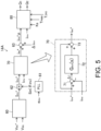
- the improved controller 14A is further configured with the AC current control unit 70 which introduces a second input current command value i inv *, and outputs a command value (a third input current command value i ac *) corresponding to the instantaneous value of the input current (AC current i ac ) flowing on the input side of the connecting position of the input-side wiring 21 with the input-side capacitor Cinv.
- the third input current command value i ac * inputted to the adder 63 with the current correction amount ⁇ i inv
- the peak current command value i inv *.p to be introduced to the peak current control unit 80 is set.
- the second current command value i inv * illustrated in Fig. 5 is a target current command value (before correction) of the AC current control unit 70
- the third current command value i ac * is an output current command value (an output value of a feedback control block) after the correction by the AC current control unit 70.
- the AC current control unit 70 has a subtractor 71, an AC current compensator 72, and a second adder 73.
- the AC current control unit 70 introduces the reactor current value i inv measured by the current sensor 10 together with the second input current command value i inv *.
- the subtractor 71 calculates a current difference value ⁇ i by subtracting the reactor current value i inv from the second input current command value i inv *.
- the current difference value ⁇ i is inputted to the AC current compensator 72 configured with a given transfer function, and an output value obtained thereby is added to the second input current command value i inv * by the second adder 73. In this manner, the AC current control unit 70 calculates and outputs the third input current command value iac*.
- Fig. 6 illustrates a block diagram of the control circuit of the peak current control unit 80.
- Fig. 7 illustrates a setting table of a lookup table provided by a determination unit 87 described later.
- Fig. 8 illustrates a switching pattern by the peak current mode control. Part (a) of Fig. 8 illustrates the switching pattern during the positive half cycle, and part (b) of Fig. 8 illustrates the switching pattern during the negative half cycle.
- controller 14 handles AC power also requiring signal processing for negative slope compensation, and therefore the peak current mode control cannot be achieved by simply using the commercially-available slope compensation function components as they are.
- the peak current control unit 80 executes the peak current mode control by using a first slope compensation circuit corresponding to the positive polarity of the input voltage e inv and a second slope compensation circuit corresponding to the negative polarity of the input voltage ei nv .
- the second slope compensation circuit includes an inversion circuit which inverts the polarity of the input voltage e inv , and is configured using the same slope compensator as the first slope compensation circuit, that is, the slope compensator corresponding to the positive polarity.
- the peak current mode control can be achieved by using only the commercially-available slope compensation function components for the slope compensator. This allows the peak current mode control to be achieved with a simple and inexpensive circuit configuration. As a result, the stable operation can be achieved even if the reactor 24 is made smaller in size.
- the peak current control unit 80 has a first slope compensator 81, a first comparator 82, a second slope compensator 83, a second comparator 84, an inverting amplifier circuit 85, a pulse width modulation (PWM) control unit 86, the determination unit 87, a gate driver 88, etc.
- the first slope compensator 81 and the first comparator 82 constitute the first slope compensation circuit
- the second slope compensator 83, the second comparator 84, and the inverting amplifier circuit 85 constitute the second slope compensation circuit.
- the first slope compensator 81 receives a positive peak current command value i inv *.p corresponding to the positive half cycle, and Ks. "Ks" corresponds to a given slope value which is applied to the positive peak current control command value i inv * p. Ks is generally used to suppress occurrence of low-frequency oscillation which occurs when the duty ratio exceeds 50%.
- the first slope compensator 81 also receives a pulse-shaped set signal T ZRO and a first reset signal T rip A. As illustrated in Fig. 8 , the set signal T ZRO is outputted at a timing corresponding to 0 degree of the switching cycle. The first reset signal T rip A is outputted at a timing corresponding to an upper limit (peak) of the reactor current i inv .
- the set signal T ZRO is inputted from the PWM control unit 86 based on the cycle signal.
- the first reset signal T rip A is outputted from the first comparator 82 and then fed back to the first slope compensator 81.
- the first slope compensator 81 sets or resets the positive peak current command value i inv *.p based on the set signal T ZRO and the first reset signal T rip A.
- the first comparator 82 compares its output value with the value of the reactor current i inv . When the output value of the first comparator 82 matches the value of the reactor current i inv (the matching portion in Part (a) of Fig. 8 ), the first comparator 82 outputs the first reset signal T rip A. The first reset signal T rip A is fed back to the first slope compensator 81. The first reset signal T rip A is also outputted to the determination unit 87.
- the second slope compensator 83 receives a negative peak current command value -i inv *.p corresponding to the negative half cycle and Ks. As with the first slope compensator 81, the second slope compensator 83 also receives the set signal T ZRO and the second reset signal T rip B. The second slope compensator 83 sets or resets the negative peak current command value -i inv *.p based on the set signal T ZRO and the second reset signal T rip B.
- the inverting amplifier circuit 85 receives the reactor current i inv and inverts the reactor current to a negative value (the negative reactor current value -i inv ).
- the second comparator 84 compares the output value from the second slope compensator 83 with the negative reactor current value -i inv .
- the second comparator 84 outputs the second reset signal T rip B.
- the second reset signal T rip B is fed back to the second slope compensator 83 and also outputted to the determination unit 87.
- the determination unit 87 disregards this signal and does not output a control signal.
- the determination unit 87 outputs the first control signal in the low state and outputs the second control signal in the high state.
- the determination unit 87 outputs the first control signal Q1 in the high state and outputs the second control signal Q2 in the low state.
- the first control signal Q1 and the second control signal Q2 thus outputted by the determination unit 87 are inputted to the gate driver 88.
- the gate driver 88 also receives a given dead time Td.
- the gate driver 88 turns the first switching element S1 ON/OFF based on the first control signal Q1, and turns the second switching element S2 ON/OFF based on the second control signal Q2. Specifically, when the first control signal Q1 is in the high state, the gate driver 88 outputs drive voltage to the first switching element S1 to turn the first switching element S1 ON. When the first control signal Q1 is in the low state, the gate driver 88 turns the first switching element S1 OFF without outputting the drive voltage thereto. The gate driver 88 turns the second switching element S2 ON/OFF in a similar manner depending on the state of the second control signal Q2.
- controller 14 as illustrated in Figs. 6 to 8 , for example, it may be such that the positive and negative peak current command values (i inv *.p, -i inv *.p) are outputted using a controller having a DAC output, and all or a part of the circuit blocks thereafter are designed using analog circuits.
- circuit parameters used in the simulations of Scenarios 1 and 2 are as follows.
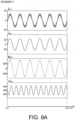
- Fig. 9A illustrates a simulation result for Scenario 1.
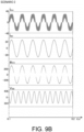
- Fig. 9B illustrates a simulation result for Scenario 2. It was confirmed that even with the small reactor 24 with the inductance of 170 ⁇ H, a reactor current with a stable waveform, which is not significantly different from that of the reactor 24 with the inductance of 340 ⁇ H, can be obtained in practice.
- the effect of the improved controller 14A was also verified. That is, the effects were compared between the cases where the AC current control unit 70 is provided and not provided. Specifically, simulations were performed in the circuit used for the situation of Scenario 2 described above, for the cases where the AC current control unit 70 is provided and not provided.
- Fig. 10 The results are illustrated in Fig. 10 .
- the left side of Fig. 10 illustrates the case without the AC current control unit 70, and the right side of Fig. 10 illustrates the case with the AC current control unit 70.
- the AC current control unit 70 was not provided, crossover distortion was observed, while when the AC current control unit 70 was provided, almost no crossover distortion was observed (see ⁇ i).
- the total harmonic distortion (THDi) of the reactor current i inv was also improved by approximately 0.5% from 3.12%.
- the peak current mode control can be performed using a simple and inexpensive circuit, making it possible to reduce the size of the reactor 24 and improving the total harmonic distortion of the reactor current i inv .
Landscapes
- Engineering & Computer Science (AREA)
- Power Engineering (AREA)
- Rectifiers (AREA)
Abstract
An alternating current/direct current (AC/DC) power converter including a bridgeless power factor correction (PFC) circuit and a controller is provided. The bridgeless PFC circuit includes input-side wirings, output-side wirings, an input-side capacitor, a reactor, and a pair of switching elements disposed between the input-side wirings and the output-side wirings, and on which a switching operation is performed by the controller. The controller includes a peak current control unit which executes a peak current mode control by using a first slope compensation circuit corresponding to a positive polarity of AC input voltage, and a second slope compensation circuit corresponding to a negative polarity of the AC input voltage. The second slope compensation circuit has an inverting circuit which inverts the polarity of the AC input voltage, and is structured using a same slope compensation circuit as the first slope compensation circuit.
Description
- The present disclosure relates to a power converter (alternating current/direct current (AC/DC) converter) which converts AC voltage to DC voltage.
- In recent years, electrification of automobiles, such as electric vehicles and hybrid vehicles, has become significantly active. These vehicles that run on electric power are equipped with high-output batteries as their power source. To charge the batteries, these vehicles are also equipped with charging systems (On Board Chargers: OBCs) that convert commercial AC power into DC power.
- Many OBCs use AC/DC converters equipped with power factor correction circuits (PFC circuits) to solve power factor reduction caused by distortion of an input current waveform (e.g.,
JP2021-069253A - The AC/DC converter equipped with such a bridgeless PFC circuit generally adopts an average current mode control since there is no need to apply slope compensation in the control method.
- However, the average current mode control has a disadvantage in which a reactor becomes large in size since the current control becomes unstable when the capacity of the reactor is small. In addition, since the switching frequency is basically the same as the control frequency, it is also disadvantageous in that it is difficult to increase the switching frequency.
- For the disclosed technology,
JP2022-129664A - One possible solution to the above-mentioned disadvantages of the average current mode control is adoption of a peak current mode control. By adopting the peak current mode control, the pulsation of the reactor current can be made larger than that of the average current mode control, and the current control is relatively stable even if the capacity of the reactor is small. Therefore, the reactor can be made smaller in size. However, in the case of the peak current mode control, the slope compensation is necessary to ensure stable operation.
- In this regard, electronic components such as integrated circuits (ICs) and microcomputers that perform the function of slope compensation are commercially available. Therefore, these electronic components (slope compensation function components) are considered to be used as the AC/DC converters equipped with the bridgeless PFC circuits.
- However, those commercially-available slope compensation function components have been developed for DC/DC converters which handle DC power, and therefore are structured to only process signals for positive slope compensation. In contrast, the AC/DC converters that handle AC power require signal processing with negative slope compensation, and therefore the peak current mode control is not possible by simply using the commercially-available slope compensation function components as they are. This is likely a significant reason why the average current mode control has become the mainstream in the AC/DC converters equipped with the bridgeless PFC circuits.
- Thus, the present disclosure discloses a technique which enables an AC/DC converter provided with a bridgeless PFC circuit to perform a peak current mode control using commercially-available slope compensation function components.
- The present disclosure relates to a power converter configured to convert AC input voltage into DC output voltage, including a converter mechanism having a bridgeless PFC circuit and a controller which controls the converter mechanism, that is, an AC/DC converter.
- The bridgeless PFC circuit includes a pair of input-side wirings which inputs the AC input voltage, a pair of output-side wirings which outputs the DC output voltage, a capacitor connected to the pair of input-side wirings, a reactor disposed in at least one of the pair of input-side wirings at a position on an output side of a connecting position with the capacitor, and a first switching element and a second switching element each disposed between one of the pair of input-side wirings and one of the pair of output-side wirings, and on which a switching operation is performed by the controller.
- The controller includes a peak current control unit which executes a peak current mode control by using a first slope compensation circuit corresponding to a positive polarity of the AC input voltage, and a second slope compensation circuit corresponding to a negative polarity of the AC input voltage. The second slope compensation circuit has an inverting circuit which inverts the polarity of the AC input voltage, and is structured using a same slope compensation circuit as the first slope compensation circuit.
- In other words, according to the power converter, the second slope compensation circuit corresponding to the negative polarity includes the inverting circuit which inverts the polarity of the input voltage, and is structured using the same slope compensation circuit as the first slope compensation circuit. Thus, the peak current mode control can be performed using commercially-available slope compensation function components, making it possible to reduce the size of the reactor and providing an AC/DC converter which is inexpensive and high in performance.
- The controller may further include a DC voltage control unit which outputs a first input current command value corresponding to the maximum value of the input current flowing in the input-side wirings on the output side from the connecting positions with the capacitor. The first input current command value may be converted to a second input current command value corresponding to an instantaneous value based on a phase of the AC input voltage. A peak current command value output to the peak current control unit may be set by adding a given current correction amount to the second input current command value.
- Thus, the peak current mode control can be performed with a relatively simple circuit.
- The controller may further include an AC current control unit which receives the second input current command value and outputs a third input current command value corresponding to an instantaneous value of the input current flowing in the input-side wirings at the connecting positions with the capacitor. The peak current command value received by the peak current control unit may be set by adding the current correction amount to the third input current command value.
- Thus, improvements in responsiveness and a distortion rate of the reactor current can be expected. In detail, crossover distortion can be suppressed. As a result, a total harmonic distortion rate of the reactor current can be improved. Therefore, it is possible to provide an AC/DC converter with higher performance.
- The bridgeless PFC circuit may include various configurations.
- For example, the bridgeless PFC circuit may further include a first diode and a second diode, and a first leg and a second leg connected in parallel to each other between the pair of output-side wirings. The first leg may be provided with the first switching element and the first diode in series so that the current flows in directions away from each other, and the second leg may be provided with the second switching element and the second diode symmetrically to the first switching element and the first diode. An output end of one of the input-side wirings may be connected to the first leg between the first switching element and the first diode, and an output end of the other one of the input-side wirings may be connected to the second leg between the second switching element and the second diode.
- Alternatively, the bridgeless PFC circuit may further include a first diode and a second diode, and a first leg and a second leg connected in parallel to each other between the pair of output-side wirings. The first leg may be provided with the first diode and the second diode in series so that the current flows in the same direction, and the second leg may be provided with the first switching element and the second switching element in series so that the current flows opposite from the first diode and the second diode. An output end of one of the input-side wirings may be connected to the first leg between the first diode and the second diode, and an output end of the other one of the input-side wirings may be connected to the second leg between the first switching element and the second switching element.
- Alternatively, the bridgeless PFC circuit may further include a first diode, a second diode, a third diode, and a fourth diode, a first leg and a second leg connected in parallel to each other between the pair of output-side wirings, and a third leg connected to the pair of input-side wirings therebetween, on the output side from the reactor. The first leg may be provided with the first diode and the second diode in series so that the current flows in the same direction, and the second leg may be provided with the third diode and the fourth diode symmetrically to the first diode and the second diode. The third leg may be provided with the first switching element and the second switching element in series so that the current flows against each other. An output end of one of the input-side wirings may be connected to the first leg between the first diode and the second diode, and an output end of the other one of the input-side wirings may be connected to the second leg between the third diode and the fourth diode.
- The present disclosure can be applied effectively to the AC/DC converters including such configurations of bridgeless PFC circuits.
-
-
Fig. 1 is a schematic diagram illustrating an application example of one embodiment of the present disclosure. -
Fig. 2 is a diagram illustrating an applicable bridgeless PFC circuit. -
Fig. 3 is a diagram illustrating a specific operation of an AC/DC converter. -
Fig. 4 is a block diagram and mathematic formulas illustrating a control circuit of a controller. -
Fig. 5 is a block diagram of a control circuit of an improved controller. -
Fig. 6 is a block diagram of a control circuit of a peak current controlling part. -
Fig. 7 is a setting table of a lookup table of a determining part. -
Fig. 8 is a diagram illustrating switching patterns applied in a peak current mode control. -
Figs. 9A and9B are diagrams illustrating simulation results. -
Fig. 10 is a diagram illustrating a simulation result. - Hereinafter, one embodiment of the present disclosure is described with reference to the accompanying drawings. Note that the following description is essentially merely illustrative. Components of circuits are annotated with specific marks along with alphanumeric codes to identify them. For the sake of convenience, the circuit components may be described or illustrated using only those marks. The capital letter "I" for current indicates its maximum value (amplitude value), and the lowercase letter "i" for current indicates its instantaneous value.
-
Fig. 1 illustrates an application example in which a power converter according to one embodiment is applied to an on-board charging system (OBC) 3. Thecharging system 3 is installed in avehicle 1 which travels using electric power, such as an electric vehicle or a hybrid vehicle, together with a high-output battery 4 for driving. - The top part of
Fig. 1 illustrates thevehicle 1 and acommercial power source 2 during charging. Thecommercial power source 2 outputs high alternating current (AC) voltages such as 100V and 200V. The battery 4 is charged by connecting thecommercial power source 2 to thevehicle 1 by a cable. Here, thecharging system 3 interposes between the battery 4 and thecommercial power source 2, and converts the AC voltage into direct current DC voltage compatible with the battery 4. - As illustrated in the middle part of
Fig. 1 , thecharging system 3 is comprised of a DC/DC converter 5, an AC/DC converter 6, etc. The AC/DC converter 6 converts AC input voltage (einv) into DC output voltage (Vdc), and is an example of a "power converter." In other words, the technology disclosed in this embodiment is applied to the AC/DC converter 6. - The DC/
DC converter 5 converts DC voltage into different DC voltage. The DC/DC converter 5 converts the DC voltage (Vdc) converted by the AC/DC converter 6 into given DC voltage (Vdc') and outputs it to the battery 4 side. - As illustrated in the lower part of
Fig. 1 , the AC/DC converter 6 includes aconverter mechanism 13 having acurrent sensor 10, aninput voltage sensor 11, anoutput voltage sensor 12, and a bridgeless power factor correction (PFC)circuit 20, and acontroller 14 which controls theconverter mechanism 13. - The
current sensor 10 is a Hall element type sensor and is installed at a given position of an input-side wiring 21, as described below. Thecurrent sensor 10 directly measures input current (reactor current iinv) flowing through areactor 24 and outputs it to thecontroller 14. Theinput voltage sensor 11 is also installed at a given position of the input-side wiring 21, and directly measures the AC input voltage einv inputted to the AC/DC converter 6 and outputs it to thecontroller 14. Theoutput voltage sensor 12 is installed at a given position of an output-side wiring 22 and directly measures the DC output voltage Vdc outputted from the AC/DC converter 6 and outputs it to thecontroller 14. - Based on these measurement values, the
controller 14 performs an ON/OFF control by outputting drive voltage to two switching elements S1 and S2 of thebridgeless PFC circuit 20. That is, thecontroller 14 switches the switching elements S1 and S2 between a conducting state (ON) and a non-conducting state (OFF) at a given timing. -
Fig. 2 illustrates types A to C of thebridgeless PFC circuit 20 applicable to the AC/DC converter 6. All of these types ofbridgeless PFC circuits 20 have a common basic circuit. - That is, each of the A-C
bridgeless PFC circuits 20 has a pair of input-side wirings 21 (an N input-side wiring 21a on the ground side and an L input-side wiring 21 b on the non-ground side), a pair of output-side wirings 22 (an N output-side wiring 22a on the negative side and a P output-side wiring 22b on the positive side), an input-side capacitor 23 (Cinv), the reactor 24 (Linv), a first switching element 25 (S1), and a second switching element 26 (S2). - The pair of input-
side wirings 21 is disposed on the side of thecommercial power source 2, and the AC input voltage einv is inputted to input terminals thereof. On the other hand, the pair of output-side wirings 22 is disposed on the side of the battery 4, and the DC output voltage Vdc is outputted from output terminals thereof. The input-side capacitor 23 is connected between the pair of input-side wirings 21 near the input terminals. - The
reactor 24 is disposed at least in one of the input-side wiring 21 at a position on the output side from a connecting point of the input-side capacitor 23. In this embodiment, thereactor 24 is disposed in the L input-side wiring 21b. While thefirst switching element 25 and thesecond switching element 26 have different positional arrangements depending on the type, they are disposed between the input-side wirings 21 and the output-side wirings 22. - Each of the
first switching element 25 and thesecond switching element 26 is made of a known MOSFET having gate, source, and drain terminals. Each of thefirst switching element 25 and thesecond switching element 26 is turned ON by receiving a given drive voltage in the gate terminal. Both thefirst switching element 25 and thesecond switching element 26 include aflyback diode 27 connected in inverse parallel to the electrical load. - In the case of the type A
bridgeless PFC circuit 20, in addition to the basic circuit described above, it further includes a first diode 31 (D1), a second diode 32 (D2), afirst leg 33, asecond leg 34, an output-side capacitor 35 (Cdc), and asecond reactor 36. Thesecond reactor 36 is arranged in the N input-side wiring 21a symmetrically to thereactor 24. Note that thesecond reactor 36 may be omitted. - The output-
side capacitor 35 is connected between the pair of output-side wirings first leg 33 and thesecond leg 34 are connected in parallel to each other between the pair of output-side wirings side capacitor 35. Further, thefirst switching element 25 and thefirst diode 31 are arranged in series in thefirst leg 33 so that the current flows in the direction away from each other. - Specifically, the
first switching element 25 and thefirst diode 31 are arranged in this order from the N output-side wiring 22a side to the P output-side wiring 22b side. In the ON state, thefirst switching element 25 is arranged so that the current flows from the P output-side wiring 22b side to the N output-side wiring 22a side, and thefirst diode 31 is arranged so that the current flows from the N output-side wiring 22a side to the P output-side wiring 22b side. - The
second switching element 26 and thesecond diode 32 are arranged in thesecond leg 34 symmetrically to thefirst switching element 25 and thefirst diode 31. - Specifically, the
second switching element 26 and thesecond diode 32 are arranged in this order from the N output-side wiring 22a side to the P output-side wiring 22b side. In the ON state, thesecond switching element 26 is arranged so that the current flows from the P output-side wiring 22b side to the N output-side wiring 22a side, and thesecond diode 32 is arranged so that the current flows from the N output-side wiring 22a side to the P output-side wiring 22b side. - An output end of the N input-
side wiring 21a is connected to thefirst leg 33 between thefirst switching element 25 and thefirst diode 31. An output end of the L input-side wiring 21b is connected to thesecond leg 34 between thesecond switching element 26 and thesecond diode 32. - In the case of the type B
bridgeless PFC circuit 20, in addition to the basic circuit described above, it further includes afirst diode 41, asecond diode 42, a third diode 43 (D3), a fourth diode 44 (D4), afirst leg 45, asecond leg 46, athird leg 47, and an output-side capacitor 48. - The output-
side capacitor 48 is connected between the pair of output-side wirings first leg 45 and thesecond leg 46 are connected in parallel to each other between the pair of output-side wirings side capacitor 48. Thethird leg 47 is connected between the pair of input-side wirings reactor 24. Thefirst diode 41 and thesecond diode 42 are arranged in series in thefirst leg 45 to have the same conductive direction. - Specifically, the
second diode 42 and thefirst diode 41 are arranged in this order from the N output-side wiring 22a side to the P output-side wiring 22b side. Further, thefirst diode 41 and thesecond diode 42 are arranged so that the current flows from the N output-side wiring 22a side to the P output-side wiring 22b side. - The
third diode 43 and thefourth diode 44 are arranged in thesecond leg 46 symmetrically to thefirst diode 41 and thesecond diode 42. Specifically, thefourth diode 44 and thethird diode 43 are arranged in this order from the N output-side wiring 22a side to the P output-side wiring 22b side. Thethird diode 43 and thefourth diode 44 are arranged so that the current flows from the N output-side wiring 22a side to the P output-side wiring 22b side. - The
first switching element 25 and thesecond switching element 26 are arranged in series in thethird leg 47 to have opposing conductive directions to each other. Specifically, thesecond switching element 26 and thefirst switching element 25 are arranged in this order from the N input-side wiring 21a side to the L input-side wiring 21b side. Thesecond switching element 26 in the ON state is arranged so that the current flows from the N input-side wiring 21a side to the L input-side wiring 21b side, and thefirst switching element 25 in the ON state is arranged so that the current flows from the L input-side wiring 21b side to the N input-side wiring 21a side. - The output end of the N input-
side wiring 21a is connected to thefirst leg 45 between thefirst diode 41 and thesecond diode 42. The output end of the L input-side wiring 21b is connected to thesecond leg 46 between thethird diode 43 and thefourth diode 44. - In the case of the type C
bridgeless PFC circuit 20, in addition to the basic circuit described above, it further includes afirst diode 51, asecond diode 52, afirst leg 53, asecond leg 54, and an output-side capacitor 55. - The output-
side capacitor 55 is connected between the pair of output-side wirings first leg 53 and thesecond leg 54 are connected in parallel to each other between the pair of output-side wirings side capacitor 55. - The
first diode 51 and thesecond diode 52 are arranged in series in thefirst leg 53 to have the same conductive direction. Specifically, thesecond diode 52 and thefirst diode 51 are arranged in this order from the N output-side wiring 22a side to the P output-side wiring 22b side. Both of thefirst diode 51 and thesecond diode 52 are arranged so that the current flows from the N output-side wiring 22a side to the P output-side wiring 22b side. - The
first switching element 25 and thesecond switching element 26 are arranged in series in thesecond leg 54 so that the current flows opposite from that in thefirst diode 51 and thesecond diode 52. Specifically, thesecond switching element 26 and thefirst switching element 25 are arranged in this order from the N output-side wiring 22a side to the P output-side wiring 22b side. Further, both of thefirst switching element 25 and thesecond switching element 26 are arranged so that the current flows from the P output-side wiring 22b side to the N output-side wiring 22a side in the ON state. - Further, the output terminal of the N input-
side wiring 21a is connected to thefirst leg 53 between thefirst diode 51 and thesecond diode 52. The output terminal of the L input-side wiring 21b is connected to thesecond leg 54 between thefirst switching element 25 and thesecond switching element 26. - A specific operation of the AC/
DC converter 6 by the control of thecontroller 14 is described with reference toFig. 3. Fig. 3 illustrates different operating states of the type Abridgeless PFC circuit 20. - A reference character R illustrated in
Fig. 3 indicates a load resistance on the side of the battery 4. Thecurrent sensor 10, theinput voltage sensor 11, and theoutput voltage sensor 12 are also illustrated in part (a) ofFig. 3 in a simplified manner. Note that although the type B and Cbridgeless PFC circuits 20 have different current paths as they have different circuit structures, since the control targets are the same first switching element S1 and second switching element S2, the explanation of the operations thereof is omitted. - In
Fig. 3 , parts (a) and (b) indicate an operation when the polarity of the input voltage einv is positive (during a positive half cycle). On the other hand, parts (c) and (d) illustrate an operation when the polarity of the input voltage einv is negative (during a negative half cycle). The operations of parts (a) to (d) are repeated according to the polarity of the input voltage einv. - In other words, the
controller 14 executes a switching operation of the first switching element S1 and the second switching element S2 according to the polarity of the input voltage einv, which changes periodically, in order to change the target of the switching operation. Specifically, when the polarity of the input voltage einv is positive, as illustrated in parts (a) and (b), the switching operations of the first switching element S1 and the second switching element S2 are performed. When the polarity of the input voltage einv is negative, as illustrated in parts (c) and (d), the switching operation of the second switching element S2 and the first switching element S1 are performed. - As illustrated in part (a), when the polarity of the input voltage einv is positive and the second switching element S2 is turned ON, input current iac flows from the L input-
side wiring 21b. Then, as indicated by a dashed arrow Y1, the input current iac flows through a current path comprised of an intermediate position of thesecond leg 34, the second switching element S2, the N output-side wiring 22a, the first switching element S1 (the flyback diode 27), an intermediate position of thefirst leg 33, and the N input-side wiring 21a. In other words, the input current iac does not flow to the battery 4 side. - As illustrated in part (b), when the polarity of the input voltage einv is positive and the second switching element S2 is turned OFF, as indicated by a dashed arrow Y2, the input current iac flowing in from the L input-
side wiring 21b flows through a current path comprised of the intermediate position of thesecond leg 34, thesecond diode 52, the P output-side wiring 22b, the load resistor R, the N output-side wiring 22a, the first switching element S1 (the flyback diode 27), the intermediate position of thefirst leg 33, and the N input-side wiring 21a. In other words, the input current iac flows to the battery 4 side. - As illustrated in part (c), when the polarity of the input voltage einv is negative and the first switching element S1 is turned ON, the input current iac flows in from the N input-
side wiring 21a. Then, as indicated by a dashed arrow Y3, the input current iac flows through a current path comprised of the intermediate position of thefirst leg 33, the first switching element S1, the N output-side wiring 22a, the second switching element S2 (the flyback diode 27), the intermediate position of thesecond leg 34, and the L input-side wiring 21b. In other words, the input current iac does not flow to the battery 4 side. - As illustrated in part (d), when the polarity of the input voltage einv is negative and the first switching element S1 is turned OFF, as illustrated by a dashed arrow Y4, the input current iac flowing in from the N input-
side wiring 21a flows through a current path comprised of the intermediate position of thefirst leg 33, the first diode D1, the P output-side wiring 22b, the load resistor R, the N output-side wiring 22a, the second switching element S2 (the flyback diode 27), the intermediate position of thesecond leg 34, and the L input-side wiring 21b. That is, the input current iac flows to the battery 4 side. - As described above, the
controller 14 outputs required output voltage command V*dc by switching between the first switching element S1 and the second switching element S2. One example of a block diagram of the control circuit provided to the ACcurrent controller 14 for this is illustrated inFig. 4 . - The AC
current controller 14 is followed by the AC current command I*inv (peak-value) of DCvoltage control unit 60 which controls the AC current so that a given level of the output voltage command V*dc is outputted in response to an output request of the output voltage Vdc, and a peakcurrent control unit 80 which controls an ON/OFF timing of the first switching element S1 and the second switching element S2. Thecontroller 14 is also configured with a phase lockedloop 61, amultiplier 62, and anadder 63. - The DC
voltage control unit 60 receives a command value Vdc* of the output voltage and an actual value Vdc of the output voltage measured by theoutput voltage sensor 12. Further, the DCvoltage control unit 60 outputs a command value (a first input current command value Iinv*) corresponding to a maximum value of the input current (a reactor current iinv) flowing in the input-side wiring 21 on the output side of a connecting position of the input-side capacitor 23, that is, thereactor 24. The actual value Vdc of the output voltage is used as a feedback value, and the DCvoltage control unit 60 controls the first input current command value Iinv* so that the actual value Vdc coincides with the command value Vdc*. - The first input current command value Iinv* is inputted to the
multiplier 62, where it is converted into a command value (a second input current command value iinv*) corresponding to an instantaneous value based on the phase of the input voltage einv. - Specifically, the actual value of the input voltage einv measured by the
input voltage sensor 11 is inputted to thephase synchronization circuit 61. The phase angle θinv of the input voltage einv is calculated based on the actual value, and a given signal (a phase signal, sin(θinv)) is outputted from thephase synchronization circuit 61 based on the phase angle θinv and received by themultiplier 62. In themultiplier 62, the first input current command value Iinv* is multiplied by the phase signal sin(θinv) to calculate the second input current command value iinv*, and this value is outputted. - The second input current command value iinv* is inputted to the
adder 63, where a given current correction amount Δiinv is added. In this way, a peak current command value iinv*.p is set as an instantaneous value to be received by the peakcurrent control unit 80. The current correction amount Δiinv is an estimated value of a pulsation component of the reactor current, and is calculated by Equation (1) illustrated inFig. 4 . - In Equations (1) to (3), "Linv" indicates an inductance of the
reactor 24. As described later, the PWM method which changes a duty ratio is used for the switching operation of the first switching element S1 and the second switching element S2. "TPWM" is a cycle signal indicating a timing corresponding to the switching cycle (a preset constant value) in the PWM control (seeFig. 8 ). "Ks" of Equation (2) is a value of a slope used for slope compensation in a peak current mode control described later. "d" of Equation (3) is a ratio of the input voltage to the output voltage. - In addition to the peak current command value iinv*.p, the actual value iinv of the reactor current measured by the
current sensor 10 is introduced as a feedback value to the peakcurrent control unit 80. Further, TPWM, Ks, and TZRO are also introduced to the peakcurrent control unit 80. "TZRO" is a set signal indicating a timing corresponding to 0 degree of the switching cycle in the PWM control. - As a result, the peak
current control unit 80 outputs control signals Q1 and Q2 indicating a timing to turn ON/OFF the first switching element S1 and the second switching element S2. -
Fig. 5 illustrates an application example of thecontroller 14 of which the control circuit is devised (animproved controller 14A). The control circuit of theimproved controller 14A is the same as that described above with addition of an ACcurrent control unit 70 between themultiplier 62 and theadder 63. - Specifically, the
improved controller 14A is further configured with the ACcurrent control unit 70 which introduces a second input current command value iinv*, and outputs a command value (a third input current command value iac*) corresponding to the instantaneous value of the input current (AC current iac) flowing on the input side of the connecting position of the input-side wiring 21 with the input-side capacitor Cinv. By adding the third input current command value iac* inputted to theadder 63 with the current correction amount Δiinv, the peak current command value iinv*.p to be introduced to the peakcurrent control unit 80 is set. Here, the second current command value iinv* illustrated inFig. 5 is a target current command value (before correction) of the ACcurrent control unit 70, and the third current command value iac* is an output current command value (an output value of a feedback control block) after the correction by the ACcurrent control unit 70. - The AC
current control unit 70 has asubtractor 71, an ACcurrent compensator 72, and asecond adder 73. The ACcurrent control unit 70 introduces the reactor current value iinv measured by thecurrent sensor 10 together with the second input current command value iinv*. Thesubtractor 71 calculates a current difference value Δi by subtracting the reactor current value iinv from the second input current command value iinv*. - The current difference value Δi is inputted to the AC
current compensator 72 configured with a given transfer function, and an output value obtained thereby is added to the second input current command value iinv* by thesecond adder 73. In this manner, the ACcurrent control unit 70 calculates and outputs the third input current command value iac*. - As described later, since the peak
current control unit 80 has a function of performing a feedback control, there is essentially no need to provide such an ACcurrent control unit 70, and since the peakcurrent control unit 80 also performs a control based on the instantaneous value, there is also a problem where the ACcurrent control unit 70 and the peakcurrent control unit 80 tend to interfere with each other. Therefore, providing such an ACcurrent control unit 70 is not commonly considered. - However, by providing such an AC
current control unit 70, improvements in responsiveness and a distortion rate of the reactor current iinv can be expected. In detail, crossover distortion, which is an inherent problem of the PFC circuit, can be suppressed. As a result, as described later, a total harmonic distortion rate of the reactor current iinv can be improved. Incidentally, the interference between the ACcurrent control unit 70 and the peakcurrent control unit 80 can be avoided by appropriately designing the ACcurrent compensator 72. -
Fig. 6 illustrates a block diagram of the control circuit of the peakcurrent control unit 80.Fig. 7 illustrates a setting table of a lookup table provided by adetermination unit 87 described later.Fig. 8 illustrates a switching pattern by the peak current mode control. Part (a) ofFig. 8 illustrates the switching pattern during the positive half cycle, and part (b) ofFig. 8 illustrates the switching pattern during the negative half cycle. - This controller 14 (or the
improved controller 14A, omitted below) is devised to be usable of inexpensive, commercially-available electronic components in order to provide the slope compensation function essential for the peak current mode control. - In other words, electronic components (slope compensation function components) such as integrated circuits (ICs) and microcomputers bearing the slope compensation function are commercially available, but these slope compensation function components have been developed for DC/DC converters which handle DC power, and are therefore structured to only be able to process signals for positive slope compensation.
- In contrast, the
controller 14 handles AC power also requiring signal processing for negative slope compensation, and therefore the peak current mode control cannot be achieved by simply using the commercially-available slope compensation function components as they are. - In this regard, in the
controller 14, the peakcurrent control unit 80 executes the peak current mode control by using a first slope compensation circuit corresponding to the positive polarity of the input voltage einv and a second slope compensation circuit corresponding to the negative polarity of the input voltage einv. The second slope compensation circuit includes an inversion circuit which inverts the polarity of the input voltage einv, and is configured using the same slope compensator as the first slope compensation circuit, that is, the slope compensator corresponding to the positive polarity. - Therefore, in the case of the
controller 14, the peak current mode control can be achieved by using only the commercially-available slope compensation function components for the slope compensator. This allows the peak current mode control to be achieved with a simple and inexpensive circuit configuration. As a result, the stable operation can be achieved even if thereactor 24 is made smaller in size. - Specifically, the peak
current control unit 80 has afirst slope compensator 81, afirst comparator 82, asecond slope compensator 83, asecond comparator 84, an invertingamplifier circuit 85, a pulse width modulation (PWM)control unit 86, thedetermination unit 87, agate driver 88, etc. Thefirst slope compensator 81 and thefirst comparator 82 constitute the first slope compensation circuit, and thesecond slope compensator 83, thesecond comparator 84, and the invertingamplifier circuit 85 constitute the second slope compensation circuit. - As described above, the
first slope compensator 81 and thesecond slope compensator 83 have the same function supporting the positive polarity of the input voltage einv, and are constructed using the commercially-available slope compensation function components, such as analog ICs and control microcomputers. - The
first slope compensator 81 receives a positive peak current command value iinv*.p corresponding to the positive half cycle, and Ks. "Ks" corresponds to a given slope value which is applied to the positive peak current control command value iinv* p. Ks is generally used to suppress occurrence of low-frequency oscillation which occurs when the duty ratio exceeds 50%. - The
first slope compensator 81 also receives a pulse-shaped set signal TZRO and a first reset signal TripA. As illustrated inFig. 8 , the set signal TZRO is outputted at a timing corresponding to 0 degree of the switching cycle. The first reset signal TripA is outputted at a timing corresponding to an upper limit (peak) of the reactor current iinv. - The set signal TZRO is inputted from the
PWM control unit 86 based on the cycle signal. The first reset signal TripA is outputted from thefirst comparator 82 and then fed back to thefirst slope compensator 81. Thefirst slope compensator 81 sets or resets the positive peak current command value iinv*.p based on the set signal TZRO and the first reset signal TripA. - The
first slope compensator 81 applies the slope to the positive peak current command value iinv*.p based on the positive peak current command value iinv*.p and Ks, and outputs a result thereof to the first comparator 82 (the sloped dashed line portion in Part (a) ofFig. 8 ). - The
first comparator 82 compares its output value with the value of the reactor current iinv. When the output value of thefirst comparator 82 matches the value of the reactor current iinv (the matching portion in Part (a) ofFig. 8 ), thefirst comparator 82 outputs the first reset signal TripA. The first reset signal TripA is fed back to thefirst slope compensator 81. The first reset signal TripA is also outputted to thedetermination unit 87. - The
second slope compensator 83 receives a negative peak current command value -iinv*.p corresponding to the negative half cycle and Ks. As with thefirst slope compensator 81, thesecond slope compensator 83 also receives the set signal TZRO and the second reset signal TripB. Thesecond slope compensator 83 sets or resets the negative peak current command value -iinv*.p based on the set signal TZRO and the second reset signal TripB. - The
second slope compensator 83 applies a slope to the negative peak current command value -iinv*.p based on the negative peak current command value -iinv*.p and Ks, and outputs a result thereof to the second comparator 84 (the sloped dashed line portion in Part (b) ofFig. 8 ). - The inverting
amplifier circuit 85 receives the reactor current iinv and inverts the reactor current to a negative value (the negative reactor current value -iinv). - The
second comparator 84 compares the output value from thesecond slope compensator 83 with the negative reactor current value -iinv. When the output value of thesecond comparator 84 matches the negative reactor current value -iinv (the matching portion in Part (b) ofFig. 8 ), thesecond comparator 84 outputs the second reset signal TripB. The second reset signal TripB is fed back to thesecond slope compensator 83 and also outputted to thedetermination unit 87. - The
determination unit 87 has a lookup table set as illustrated in the table inFig. 7 . Thedetermination unit 87 determines the inputted first and second reset signals TripA and TripB based on the phase signal inputted from thephase synchronization circuit 61 and the lookup table. As a result, thedetermination unit 87 outputs control signals (the first control signal Q1 and the second control signal Q2) to turn ON/OFF the first switching element S1 and the second switching element S2. - Specifically, as illustrated in Part (a) of
Fig. 8 , when the phase signal sin(θinv) is equal to or greater than 0, that is, during the positive half cycle, if the first reset signal TripA is inputted, thedetermination unit 87 outputs the first control signal Q1 in a high state and outputs the second control signal Q2 in a low state. On the other hand, even if the second reset signal TripB is inputted, thedetermination unit 87 disregards this signal and does not output a control signal. When the set signal TPWM is inputted, thedetermination unit 87 outputs the first control signal Q1 in a low state and outputs the second control signal in a high state. - Further, as illustrated in Part (b) of
Fig. 8 , when the phase signal sin(θinv) is less than 0, that is, during the negative half cycle, even if the first reset signal is inputted, thedetermination unit 87 disregards this signal and does not output a control signal. On the other hand, when the second reset signal is inputted, thedetermination unit 87 outputs the first control signal in the low state and outputs the second control signal in the high state. When the set signal is inputted, thedetermination unit 87 outputs the first control signal Q1 in the high state and outputs the second control signal Q2 in the low state. - As illustrated in
Fig. 6 , the first control signal Q1 and the second control signal Q2 thus outputted by thedetermination unit 87 are inputted to thegate driver 88. Thegate driver 88 also receives a given dead time Td. - The
gate driver 88 turns the first switching element S1 ON/OFF based on the first control signal Q1, and turns the second switching element S2 ON/OFF based on the second control signal Q2. Specifically, when the first control signal Q1 is in the high state, thegate driver 88 outputs drive voltage to the first switching element S1 to turn the first switching element S1 ON. When the first control signal Q1 is in the low state, thegate driver 88 turns the first switching element S1 OFF without outputting the drive voltage thereto. Thegate driver 88 turns the second switching element S2 ON/OFF in a similar manner depending on the state of the second control signal Q2. - While the present disclosure is realized using the
controller 14 as illustrated inFigs. 6 to 8 , for example, it may be such that the positive and negative peak current command values (iinv*.p, -iinv*.p) are outputted using a controller having a DAC output, and all or a part of the circuit blocks thereafter are designed using analog circuits. - Simulations were performed for two scenarios to verify the effect(s) of miniaturizing the
reactor 24. The inductance of thereactor 24 inScenario 1 was set to 340 µH. InScenario 2, the inductance of thereactor 24 was set to the half ofScenario 1, 170 µH. - The circuit parameters used in the simulations of
Scenarios - Capacity of input capacitor 23 (Cinv): 5.5 µF
- PWM frequency: 24 kHz
- Input voltage (einv): 240 V/60 Hz
- DC load: 4 kW
- Dead time: 2 µs
- Capacity of output capacitor 55 (Cdc): 2200 µF
- Output voltage (Vdc): 400 V.
-
Fig. 9A illustrates a simulation result forScenario 1.Fig. 9B illustrates a simulation result forScenario 2. It was confirmed that even with thesmall reactor 24 with the inductance of 170 µH, a reactor current with a stable waveform, which is not significantly different from that of thereactor 24 with the inductance of 340 µH, can be obtained in practice. - In other words, according to the present disclosure, it is possible to reduce the inductance of the
reactor 24 to 170 µH or less. - Furthermore, the effect of the
improved controller 14A was also verified. That is, the effects were compared between the cases where the ACcurrent control unit 70 is provided and not provided. Specifically, simulations were performed in the circuit used for the situation ofScenario 2 described above, for the cases where the ACcurrent control unit 70 is provided and not provided. - The results are illustrated in
Fig. 10 . The left side ofFig. 10 illustrates the case without the ACcurrent control unit 70, and the right side ofFig. 10 illustrates the case with the ACcurrent control unit 70. When the ACcurrent control unit 70 was not provided, crossover distortion was observed, while when the ACcurrent control unit 70 was provided, almost no crossover distortion was observed (see Δi). - As a result, it was confirmed that the total harmonic distortion (THDi) of the reactor current iinv was also improved by approximately 0.5% from 3.12%.
- Thus, according to the present disclosure, the peak current mode control can be performed using a simple and inexpensive circuit, making it possible to reduce the size of the
reactor 24 and improving the total harmonic distortion of the reactor current iinv. - It should be understood that the embodiments herein are illustrative and not restrictive, since the scope of the invention is defined by the appended claims rather than by the description preceding them, and all changes that fall within metes and bounds of the claims, or equivalence of such metes and bounds thereof, are therefore intended to be embraced by the claims.
-
- 1
- Vehicle
- 2
- Commercial Power Source
- 3
- Charging System
- 4
- Battery
- 5
- DC/DC Converter
- 6
- AC/DC Converter (Power Converter)
- 10
- Current Sensor
- 11
- Input Voltage Sensor
- 12
- Output Voltage Sensor
- 13
- Converter Mechanism
- 14
- Controller
- 14A
- Improved Controller
- 20
- Bridgeless PFC Circuit
- 21
- Input-side Wiring
- 21a
- N Input-side Wiring
- 21b
- L Input-side Wiring
- 22
- Output-side Wiring
- 22a
- N Output-side Wiring
- 22b
- P Output-side Wiring
- 23
- Input Capacitor
- 24
- Reactor
- 25
- First Switching Element
- 26
- Second Switching Element
- 27
- Flyback Diode
- 31
- First Diode
- 32
- Second Diode
- 33
- First Leg
- 34
- Second Leg
- 35
- Output-side Capacitor
- 36
- Second Reactor
- 41
- First Diode
- 42
- Second Diode
- 43
- Third Diode
- 44
- Fourth Diode
- 45
- First Leg
- 46
- Second Leg
- 47
- Third Leg
- 48
- Output-side Capacitor
- 51
- First Diode
- 52
- Second Diode
- 53
- First Leg
- 54
- Second Leg
- 55
- Output-side Capacitor
- 60
- DC Voltage Control Unit
- 61
- Phase Locked Loop
- 62
- Multiplier
- 63
- Adder
- 70
- AC Current Control Unit
- 80
- Peak Current Control Unit
- 81
- First Slope Compensator
- 82
- First Comparator
- 83
- Second Slope Compensator
- 84
- Second Comparator
- 85
- Inverting Amplifier Circuit (Inverting Circuit)
- 86
- PWM Control Unit
- 87
- Determination Unit
- 88
- Gate Driver
Claims (15)
- A power converter (6) configured to convert alternating current (AC) input voltage into direct current (DC) output voltage, comprising:a converter mechanism (13) having a bridgeless power factor correction (PFC) circuit (20); anda controller (14) configured to control the converter mechanism (13),wherein the bridgeless PFC circuit (20) includes:a pair of input-side wirings (21) configured to input the AC input voltage;a pair of output-side wirings (22) configured to output the DC output voltage;a capacitor (23) connected to the pair of input-side wirings (21);a reactor (24) disposed in at least one of the pair of input-side wirings (21) at a position on an output side of a connecting position with the capacitor (23); anda first switching element (25) and a second switching element (26) each disposed between one of the pair of input-side wirings (21) and one of the pair of output-side wirings (22), and on which a switching operation is performed by the controller (14),wherein the controller (14) includes a peak current control unit (80) configured to execute a peak current mode control by using a first slope compensation circuit (81) corresponding to a positive polarity of the AC input voltage, and a second slope compensation circuit (83) corresponding to a negative polarity of the AC input voltage, andwherein the second slope compensation circuit (83) has an inverting circuit (85) configured to invert the polarity of the AC input voltage, and is structured using a same slope compensation circuit as the first slope compensation circuit (81).
- The power converter (6) of claim 1, wherein the controller (14) further includes a DC voltage control unit (60) configured to output a first input current command value corresponding to the maximum value of the input current flowing in the input-side wirings (21) on the output side from the connecting positions with the capacitor (23), wherein the first input current command value is converted to a second input current command value corresponding to an instantaneous value based on a phase of the AC input voltage, and wherein a peak current command value output to the peak current control unit (80) is set by adding a given current correction amount to the second input current command value.
- The power converter (6) of claim 2, wherein the controller (14) further includes an AC current control unit (70) configured to receive the second input current command value and output a third input current command value corresponding to an instantaneous value of the input current flowing in the input-side wirings (21) at the connecting positions with the capacitor (23), and wherein the peak current command value received by the peak current control unit (80) is set by adding the current correction amount to the third input current command value.
- The power converter (6) of claim 1, wherein the bridgeless PFC circuit (20) further includes:a first diode (31) and a second diode (32); anda first leg (33) and a second leg (34) connected in parallel to each other between the pair of output-side wirings (22),wherein the first leg (33) is provided with the first switching element (25) and the first diode (31) in series so that the current flows in directions away from each other, and the second leg (34) is provided with the second switching element (26) and the second diode (32) symmetrically to the first switching element (25) and the first diode (31), andwherein an output end of one of the input-side wirings (21a) is connected to the first leg (33) between the first switching element (25) and the first diode (31), and an output end of the other one of the input-side wirings (21b) is connected to the second leg (34) between the second switching element (26) and the second diode (32).
- The power converter (6) of claim 2, wherein the bridgeless PFC circuit (20) further includes:a first diode (31) and a second diode (32); anda first leg (33) and a second leg (34) connected in parallel to each other between the pair of output-side wirings (22),wherein the first leg (33) is provided with the first switching element (25) and the first diode (31) in series so that the current flows in directions away from each other, and the second leg (34) is provided with the second switching element (26) and the second diode (32) symmetrically to the first switching element (25) and the first diode (31), andwherein an output end of one of the input-side wirings (21a) is connected to the first leg (33) between the first switching element (25) and the first diode (31), and an output end of the other one of the input-side wirings (21b) is connected to the second leg (34) between the second switching element (26) and the second diode (32).
- The power converter (6) of claim 3, wherein the bridgeless PFC circuit (20) further includes:a first diode (31) and a second diode (32); anda first leg (33) and a second leg (34) connected in parallel to each other between the pair of output-side wirings (22),wherein the first leg (33) is provided with the first switching element (25) and the first diode (31) in series so that the current flows in directions away from each other, and the second leg (34) is provided with the second switching element (26) and the second diode (32) symmetrically to the first switching element (25) and the first diode (31), andwherein an output end of one of the input-side wirings (21a) is connected to the first leg (33) between the first switching element (25) and the first diode (31), and an output end of the other one of the input-side wirings (21b) is connected to the second leg (34) between the second switching element (26) and the second diode (32).
- The power converter (6) of claim 1, wherein the bridgeless PFC circuit (20) further includes:a first diode (51) and a second diode (52); anda first leg (53) and a second leg (54) connected in parallel to each other between the pair of output-side wirings (22),wherein the first leg (53) is provided with the first diode (51) and the second diode (52) in series so that the current flows in the same direction, and the second leg (54) is provided with the first switching element (25) and the second switching element (26) in series so that the current flows opposite from the first diode (51) and the second diode (52), andwherein an output end of one of the input-side wirings (21a) is connected to the first leg (53) between the first diode (51) and the second diode (52), and an output end of the other one of the input-side wirings (21b) is connected to the second leg (54) between the first switching element (25) and the second switching element (26).
- The power converter (6) of claim 2, wherein the bridgeless PFC circuit (20) further includes:a first diode (51) and a second diode (52); anda first leg (53) and a second leg (54) connected in parallel to each other between the pair of output-side wirings (22),wherein the first leg (53) is provided with the first diode (51) and the second diode (52) in series so that the current flows in the same direction, and the second leg (54) is provided with the first switching element (25) and the second switching element (26) in series so that the current flows opposite from the first diode (51) and the second diode (52), andwherein an output end of one of the input-side wirings (21a) is connected to the first leg (53) between the first diode (51) and the second diode (52), and an output end of the other one of the input-side wirings (21b) is connected to the second leg (54) between the first switching element (25) and the second switching element (26).
- The power converter (6) of claim 3, wherein the bridgeless PFC circuit (20) further includes:a first diode (51) and a second diode (52); anda first leg (53) and a second leg (54) connected in parallel to each other between the pair of output-side wirings (22),wherein the first leg (53) is provided with the first diode (51) and the second diode (52) in series so that the current flows in the same direction, and the second leg (54) is provided with the first switching element (25) and the second switching element (26) in series so that the current flows opposite from the first diode (51) and the second diode (52), andwherein an output end of one of the input-side wirings (21a) is connected to the first leg (53) between the first diode (51) and the second diode (52), and an output end of the other one of the input-side wirings (21b) is connected to the second leg (54) between the first switching element (25) and the second switching element (26).
- The power converter (6) of claim 1, wherein the bridgeless PFC circuit (20) further includes:a first diode (41), a second diode (42), a third diode (43), and a fourth diode (44);a first leg (45) and a second leg (46) connected in parallel to each other between the pair of output-side wirings (22); anda third leg (47) connected to the pair of input-side wirings (21) therebetween, on the output side from the reactor (24),wherein the first leg (45) is provided with the first diode (41) and the second diode (42) in series so that the current flows in the same direction, and the second leg (46) is provided with the third diode (43) and the fourth diode (44) symmetrically to the first diode (41) and the second diode (42),wherein the third leg (47) is provided with the first switching element (25) and the second switching element (26) in series so that the current flows against each other, andwherein an output end of one of the input-side wirings (21a) is connected to the first leg (45) between the first diode (41) and the second diode (42), and an output end of the other one of the input-side wirings (21b) is connected to the second leg (46) between the third diode (43) and the fourth diode (44).
- The power converter (6) of claim 2, wherein the bridgeless PFC circuit (20) further includes:a first diode (41), a second diode (42), a third diode (43), and a fourth diode (44);a first leg (45) and a second leg (46) connected in parallel to each other between the pair of output-side wirings (22); anda third leg (47) connected to the pair of input-side wirings (21) therebetween, on the output side from the reactor (24),wherein the first leg (45) is provided with the first diode (41) and the second diode (42) in series so that the current flows in the same direction, and the second leg (46) is provided with the third diode (43) and the fourth diode (44) symmetrically to the first diode (41) and the second diode (42),wherein the third leg (47) is provided with the first switching element (25) and the second switching element (26) in series so that the current flows against each other, andwherein an output end of one of the input-side wirings (21a) is connected to the first leg (45) between the first diode (41) and the second diode (42), and an output end of the other one of the input-side wirings (21b) is connected to the second leg (46) between the third diode (43) and the fourth diode (44)."
- The power converter (6) of claim 3, wherein the bridgeless PFC circuit (20) further includes:a first diode (41), a second diode (42), a third diode (43), and a fourth diode (44);a first leg (45) and a second leg (46) connected in parallel to each other between the pair of output-side wirings (22); anda third leg (47) connected to the pair of input-side wirings(21), on the output side of the reactor (24),wherein the first leg (45) is provided with the first diode (41) and the second diode (42) in series so that the current flows in the same direction, and the second leg (46) is provided with the third diode (43) and the fourth diode (44) symmetrically to the first diode (41) and the second diode (42),wherein the third leg (47) is provided with the first switching element (25) and the second switching element (26) in series so that the current flows in opposing directions, andwherein an output end of one of the input-side wirings (21a) is connected to the first leg (45) between the first diode (41) and the second diode (42), and an output end of the other one of the input-side wirings (21b) is connected to the second leg (46) between the third diode (43) and the fourth diode (44).
- The power converter according to claim 1, wherein the controller (14) further comprises a phase-locked loop (61) configured to perform phase synchronization of the AC input voltage (einv) and outputs phase information used to determine the timing for controlling the first and second switching elements (25, 26).
- The power converter according to claim 3, wherein the AC current control unit (70) comprises a subtraction unit (71) configured to calculate a current difference value (Δi) by subtracting the actual reactor current value (iinv) from the second input current command value (iinv*), wherein the current difference value (Δi) serves as a feedback value to improve responsiveness and reduce distortion of the reactor current.
- The power converter according to claim 1, wherein the first and second switching elements (25, 26) are controlled by a driver (88) that sets a dead time (Td) between the switching operations of the switching elements to prevent overlap of conduction phases, thereby increasing the reliability of the system.
Applications Claiming Priority (1)
| Application Number | Priority Date | Filing Date | Title |
|---|---|---|---|
| JP2023206348A JP2025091211A (en) | 2023-12-06 | 2023-12-06 | Power Conversion Equipment |
Publications (1)
| Publication Number | Publication Date |
|---|---|
| EP4576528A1 true EP4576528A1 (en) | 2025-06-25 |
Family
ID=93704863
Family Applications (1)
| Application Number | Title | Priority Date | Filing Date |
|---|---|---|---|
| EP24215788.1A Pending EP4576528A1 (en) | 2023-12-06 | 2024-11-27 | Power converter |
Country Status (4)
| Country | Link |
|---|---|
| US (1) | US20250192669A1 (en) |
| EP (1) | EP4576528A1 (en) |
| JP (1) | JP2025091211A (en) |
| CN (1) | CN120110154A (en) |
Citations (5)
| Publication number | Priority date | Publication date | Assignee | Title |
|---|---|---|---|---|
| US20130207621A1 (en) * | 2012-02-09 | 2013-08-15 | Minebea Co., Ltd. | Power factor correction circuit |
| JP2019054616A (en) * | 2017-09-14 | 2019-04-04 | 株式会社豊田自動織機 | Power factor improvement circuit and charger |
| JP2021069253A (en) | 2019-10-28 | 2021-04-30 | ローム株式会社 | Control device of power factor improvement circuit, power factor improvement circuit, power supply device, and semiconductor device |
| JP2022129664A (en) | 2021-02-25 | 2022-09-06 | サンケン電気株式会社 | Integrated circuit and method for performing synchronous rectification control of bridgeless power factor improvement circuit |
| CN114039476B (en) * | 2021-07-20 | 2023-08-29 | 杰华特微电子股份有限公司 | Power Factor Correction Method and Correction Circuit for Bridgeless Converter |
-
2023
- 2023-12-06 JP JP2023206348A patent/JP2025091211A/en active Pending
-
2024
- 2024-10-25 US US18/926,859 patent/US20250192669A1/en active Pending
- 2024-11-13 CN CN202411616893.2A patent/CN120110154A/en active Pending
- 2024-11-27 EP EP24215788.1A patent/EP4576528A1/en active Pending
Patent Citations (5)
| Publication number | Priority date | Publication date | Assignee | Title |
|---|---|---|---|---|
| US20130207621A1 (en) * | 2012-02-09 | 2013-08-15 | Minebea Co., Ltd. | Power factor correction circuit |
| JP2019054616A (en) * | 2017-09-14 | 2019-04-04 | 株式会社豊田自動織機 | Power factor improvement circuit and charger |
| JP2021069253A (en) | 2019-10-28 | 2021-04-30 | ローム株式会社 | Control device of power factor improvement circuit, power factor improvement circuit, power supply device, and semiconductor device |
| JP2022129664A (en) | 2021-02-25 | 2022-09-06 | サンケン電気株式会社 | Integrated circuit and method for performing synchronous rectification control of bridgeless power factor improvement circuit |
| CN114039476B (en) * | 2021-07-20 | 2023-08-29 | 杰华特微电子股份有限公司 | Power Factor Correction Method and Correction Circuit for Bridgeless Converter |
Non-Patent Citations (2)
| Title |
|---|
| HUANG QINGYUN ET AL: "Predictive ZVS Control With Improved ZVS Time Margin and Limited Variable Frequency Range for a 99% Efficient, 130-W/in3 MHz GaN Totem-Pole PFC Rectifier", IEEE TRANSACTIONS ON POWER ELECTRONICS, INSTITUTE OF ELECTRICAL AND ELECTRONICS ENGINEERS, USA, vol. 34, no. 7, 1 July 2019 (2019-07-01), pages 7079 - 7091, XP011722111, ISSN: 0885-8993, [retrieved on 20190430], DOI: 10.1109/TPEL.2018.2877443 * |
| LEE YOUNG-DAL ET AL: "New Bridgeless Power Factor Correction Converter With Simple Gate Driving Circuit and High Efficiency for Server Power Applications", IEEE TRANSACTIONS ON POWER ELECTRONICS, INSTITUTE OF ELECTRICAL AND ELECTRONICS ENGINEERS, USA, vol. 35, no. 12, 14 May 2020 (2020-05-14), pages 13148 - 13156, XP011802964, ISSN: 0885-8993, [retrieved on 20200804], DOI: 10.1109/TPEL.2020.2994544 * |
Also Published As
| Publication number | Publication date |
|---|---|
| US20250192669A1 (en) | 2025-06-12 |
| JP2025091211A (en) | 2025-06-18 |
| CN120110154A (en) | 2025-06-06 |
Similar Documents
| Publication | Publication Date | Title |
|---|---|---|
| CN110086367B9 (en) | Device for controlling a DC-AC converter | |
| US8693221B2 (en) | Electric power converter apparatus | |
| CN101647192B (en) | Motor drive control device and drive control method | |
| US10097106B1 (en) | Power converter | |
| US9093929B2 (en) | Circuit arrangements and methods for operating an electrical machine | |
| US11817768B2 (en) | Power conversion device that can suppress interference between control of input current from an AC power supply and voltage control for a DC capacitor | |
| WO2017221339A1 (en) | Power conversion device | |
| US20250357880A1 (en) | Power conversion apparatus | |
| CN106487227A (en) | Transformation of electrical energy circuit | |
| US20250192669A1 (en) | Power converter | |
| KR20190040326A (en) | Method for controlling a three-phase rectifier for a charging device mounted on an electric or hybrid vehicle | |
| US11518257B2 (en) | Method for controlling the input voltage frequency of a DC-DC convertor | |
| US9634578B2 (en) | Current zero crossing in an inverter | |
| JP7089377B2 (en) | Power converter | |
| JP2020115719A (en) | Power control method and power controller | |
| CN116742957A (en) | Systems and methods for providing compensation factors for DC/DC converters | |
| JP2022090317A (en) | Inverter control device, and control method of inverter | |
| WO2022158195A1 (en) | Inverter device | |
| US11342845B2 (en) | Method for switching a bi-directional voltage converter | |
| EP4683197A1 (en) | Ac/dc converter, method of controlling an ac/dc converter and computer program product | |
| JP6943110B2 (en) | Power converter | |
| CN120130019A (en) | Power conversion device, program | |
| JP2026054860A (en) | Power converters and on-board chargers | |
| JPH01298959A (en) | Pwm converter | |
| WO2024219186A1 (en) | Power conversion device and program |
Legal Events
| Date | Code | Title | Description |
|---|---|---|---|
| PUAI | Public reference made under article 153(3) epc to a published international application that has entered the european phase |
Free format text: ORIGINAL CODE: 0009012 |
|
| STAA | Information on the status of an ep patent application or granted ep patent |
Free format text: STATUS: THE APPLICATION HAS BEEN PUBLISHED |
|
| AK | Designated contracting states |
Kind code of ref document: A1 Designated state(s): AL AT BE BG CH CY CZ DE DK EE ES FI FR GB GR HR HU IE IS IT LI LT LU LV MC ME MK MT NL NO PL PT RO RS SE SI SK SM TR |
|
| RIN1 | Information on inventor provided before grant (corrected) |
Inventor name: LUNG, CHIENRU |
|
| STAA | Information on the status of an ep patent application or granted ep patent |
Free format text: STATUS: REQUEST FOR EXAMINATION WAS MADE |
|
| 17P | Request for examination filed |
Effective date: 20251211 |