EP4576287A1 - Redox flow battery system - Google Patents
Redox flow battery system Download PDFInfo
- Publication number
- EP4576287A1 EP4576287A1 EP23854763.2A EP23854763A EP4576287A1 EP 4576287 A1 EP4576287 A1 EP 4576287A1 EP 23854763 A EP23854763 A EP 23854763A EP 4576287 A1 EP4576287 A1 EP 4576287A1
- Authority
- EP
- European Patent Office
- Prior art keywords
- electrolyte
- ions
- positive
- negative
- concentration
- Prior art date
- Legal status (The legal status is an assumption and is not a legal conclusion. Google has not performed a legal analysis and makes no representation as to the accuracy of the status listed.)
- Pending
Links
Images

Classifications
-
- H—ELECTRICITY
- H01—ELECTRIC ELEMENTS
- H01M—PROCESSES OR MEANS, e.g. BATTERIES, FOR THE DIRECT CONVERSION OF CHEMICAL ENERGY INTO ELECTRICAL ENERGY
- H01M8/00—Fuel cells; Manufacture thereof
- H01M8/18—Regenerative fuel cells, e.g. redox flow batteries or secondary fuel cells
- H01M8/184—Regeneration by electrochemical means
- H01M8/188—Regeneration by electrochemical means by recharging of redox couples containing fluids; Redox flow type batteries
-
- H—ELECTRICITY
- H01—ELECTRIC ELEMENTS
- H01M—PROCESSES OR MEANS, e.g. BATTERIES, FOR THE DIRECT CONVERSION OF CHEMICAL ENERGY INTO ELECTRICAL ENERGY
- H01M8/00—Fuel cells; Manufacture thereof
- H01M8/04—Auxiliary arrangements, e.g. for control of pressure or for circulation of fluids
- H01M8/04082—Arrangements for control of reactant parameters, e.g. pressure or concentration
- H01M8/04186—Arrangements for control of reactant parameters, e.g. pressure or concentration of liquid-charged or electrolyte-charged reactants
-
- H—ELECTRICITY
- H01—ELECTRIC ELEMENTS
- H01M—PROCESSES OR MEANS, e.g. BATTERIES, FOR THE DIRECT CONVERSION OF CHEMICAL ENERGY INTO ELECTRICAL ENERGY
- H01M8/00—Fuel cells; Manufacture thereof
- H01M8/08—Fuel cells with aqueous electrolytes
-
- H—ELECTRICITY
- H01—ELECTRIC ELEMENTS
- H01M—PROCESSES OR MEANS, e.g. BATTERIES, FOR THE DIRECT CONVERSION OF CHEMICAL ENERGY INTO ELECTRICAL ENERGY
- H01M8/00—Fuel cells; Manufacture thereof
- H01M8/18—Regenerative fuel cells, e.g. redox flow batteries or secondary fuel cells
-
- H—ELECTRICITY
- H01—ELECTRIC ELEMENTS
- H01M—PROCESSES OR MEANS, e.g. BATTERIES, FOR THE DIRECT CONVERSION OF CHEMICAL ENERGY INTO ELECTRICAL ENERGY
- H01M2300/00—Electrolytes
- H01M2300/0002—Aqueous electrolytes
- H01M2300/0005—Acid electrolytes
- H01M2300/0011—Sulfuric acid-based
-
- Y—GENERAL TAGGING OF NEW TECHNOLOGICAL DEVELOPMENTS; GENERAL TAGGING OF CROSS-SECTIONAL TECHNOLOGIES SPANNING OVER SEVERAL SECTIONS OF THE IPC; TECHNICAL SUBJECTS COVERED BY FORMER USPC CROSS-REFERENCE ART COLLECTIONS [XRACs] AND DIGESTS
- Y02—TECHNOLOGIES OR APPLICATIONS FOR MITIGATION OR ADAPTATION AGAINST CLIMATE CHANGE
- Y02E—REDUCTION OF GREENHOUSE GAS [GHG] EMISSIONS, RELATED TO ENERGY GENERATION, TRANSMISSION OR DISTRIBUTION
- Y02E60/00—Enabling technologies; Technologies with a potential or indirect contribution to GHG emissions mitigation
- Y02E60/30—Hydrogen technology
- Y02E60/50—Fuel cells
Definitions
- the present disclosure relates to a redox-flow battery system.
- the present application claims the benefit of priority to Japanese Patent Application No. 2022-129609 filed on August 16, 2022 , the entire contents of which are incorporated herein by reference.
- redox-flow battery systems As a large-capacity rechargeable battery, redox-flow battery systems are known. In a redox-flow battery system, charging and discharging take place through circulation of a positive electrolyte and a negative electrolyte within a battery cell.
- a redox-flow battery system may be also expressed as an RF battery system.
- PTL 1 discloses a vanadium-based RF battery.
- PTL 2 discloses a manganese-titanium-based RF battery.
- iron-chromium-based RF batteries and the like are known.
- both the positive electrode active material and the negative electrode active material are vanadium (V) ions.
- the positive electrode active material is manganese (Mn) ions and the negative electrode active material is titanium (Ti) ions.
- the positive electrode active material is iron (Fe) ions and the negative electrode active material is chromium (Cr) ions.
- electrolyte collectively refers to a positive electrolyte and a negative electrolyte.
- a redox-flow battery system comprises:
- a pressure difference may occur between the positive electrolyte and the negative electrolyte.
- the pressure difference may occur due to a change in the state of charge (SOC) of the electrolyte.
- SOC state of charge
- fibers that constitute an electrode can pierce the membrane to form pinholes in the membrane.
- one of the positive electrolyte and the negative electrolyte may diffuse through the pinholes to reach the other electrolyte.
- the positive electrolyte and the negative electrolyte are mixed with each other, and, thereby, battery performance is degraded.
- An object of the present disclosure is to provide a redox-flow battery system which is capable of reducing electrolyte diffusion that can occur due to a pressure difference between a positive electrolyte and a negative electrolyte within a battery cell.
- a redox-flow battery system is capable of reducing electrolyte diffusion that can occur due to a pressure difference between a positive electrolyte and a negative electrolyte.
- the pressure of the electrolyte tends to increase.
- the pressure difference between the positive electrolyte and the negative electrolyte within the battery cell is too large, there is a possibility that a load can be applied on the membrane by the high-pressure electrolyte to damage the membrane.
- the high-pressure electrolyte can crush the electrode in which the low-pressure electrolyte is flowing. This can reduce flowability of the electrolyte in the crushed electrode.
- the ratio P1/P2 falls within the above-mentioned range, the pressure difference between the pressure of the positive electrolyte and the pressure of the negative electrolyte within the battery cell does not become too large. As a result, problems that can be caused by an excessive pressure difference tend not to occur.
- the ratio P1/P2 When the ratio P1/P2 is close to 1, namely, when the difference between the kinematic viscosity P1 and the kinematic viscosity P2 is very small, diffusion at the contact interface between the positive electrolyte and the negative electrolyte tends to occur. As a result, when there are pinholes in the membrane, the positive electrolyte and the negative electrolyte with a ratio P1/P2 close to 1 tend to pass through the pinholes and become mixed with each other. On the other hand, the positive electrolyte and the negative electrolyte with a ratio P1/P2 being 0.97 or less or 1.05 or more tend not to pass through the pinholes and thereby not to become mixed with each other.
- the kinematic viscosity of the electrolyte changes depending on the concentration of the active material included in the electrolyte.
- a positive electrolyte with a kinematic viscosity P1 of 0.70 ⁇ 10 -2 cm 2 /s or more includes a sufficient amount of positive electrode active material.
- a negative electrolyte with a kinematic viscosity P2 of 0.75 ⁇ 10 -2 cm 2 /s or more includes a sufficient amount of negative electrode active material.
- a redox-flow battery system comprising a positive electrolyte and a negative electrolyte of this type has a sufficient level of discharged capacity.
- a positive electrode active material included in the positive electrolyte and a negative electrode active material included in the negative electrolyte may be vanadium ions.
- the type of metal ions in the positive electrolyte is the same as the type of metal ions in the negative electrolyte.
- This configuration has the following effects, for example. (1) This configuration can prevent the movement of metal ions across the membrane of the battery cell to reach the counter electrode to cause a relative decrease of metal ions available for reactions at the electrodes. (2) When the electrolyte moves during charging and discharging and, thereby, the amount of electrolyte and the concentration of ions become different between the two electrodes, the configuration allows for mixing of the electrolyte to occur between the two electrodes to easily eliminate the differences.
- the above-mentioned electrolyte movement refers to a phenomenon where the electrolyte moves from one electrode to the other electrode over time across the membrane.
- the configuration allows for simultaneously producing both the positive electrolyte and the negative electrolyte.
- the positive electrolyte includes a sufficient amount of positive electrode active material.
- the negative electrolyte includes a sufficient amount of negative electrode active material. Accordingly, the redox-flow battery system according to ⁇ 5> above is capable of ensuring a high discharged capacity.
- the concentration of hydrogen ions in the electrolyte is high. Hydrogen ions permeate through the membrane of the battery cell to play a part in battery reactions.
- the concentration of sulfuric acid in the electrolyte increases, the kinematic viscosity of the electrolyte increases.
- the positive electrolyte and the negative electrolyte both including sulfuric acid within the above-mentioned concentration range tend to satisfy the range of the ratio P1/P2 according to ⁇ 2> above.
- RF battery system 1 is an electrolytecirculation-type rechargeable battery.
- charging and discharging take place through changes of valences of a positive electrode active material included in a positive electrolyte 6 and a negative electrode active material included in a negative electrolyte 7.
- the positive electrode active material and the negative electrode active material are metal ions the valence of which changes along with oxidation and reduction.
- the solid arrows mean charging, and the broken arrows mean discharging.
- RF battery system 1 is connected to a power system 9 via a power converter 8.
- power converter 8 is connected to a transformer facility 91 of the power system.
- Power converter 8 is an AC/DC converter, a DC/DC converter, or the like.
- RF battery system 1 is charged with electric power that is generated in an electric power generating unit 90, and discharges the electric power thus charged to a load 92.
- electric power generating unit 90 is an electric power generation facility or otherwise an ordinary power plant that uses natural energy to perform photovoltaic power generation, wind power generation, and/or the like.
- RF battery system 1 is used for load leveling, instantaneous voltage drop compensation, emergency power source, and output smoothing in natural energy power generation, for example.
- RF battery system 1 comprises a battery cell 10, a first circulation mechanism 11, and a second circulation mechanism 12.
- Battery cell 10 performs charging and discharging.
- First circulation mechanism 11 circulates positive electrolyte 6.
- Second circulation mechanism 12 circulates negative electrolyte 7.
- Battery cell 10 is divided by a membrane 101 into a positive electrode cell 102 and a negative electrode cell 103.
- Membrane 101 is an ion-exchange membrane that does not allow permeation of electrons across itself but allows permeation of, for example, hydrogen ions (H + ions). By hydrogen ions, electric charges are exchanged between positive electrode cell 102 and negative electrode cell 103.
- Positive electrode cell 102 internally includes a positive electrode 104.
- Negative electrode cell 103 internally includes a negative electrode 105.
- To positive electrode cell 102 the positive electrolyte is supplied by first circulation mechanism 11.
- To negative electrode cell 103 the negative electrolyte is supplied by second circulation mechanism 12.
- Each of positive electrode 104 and negative electrode 105 is an electricallyconductive porous body.
- the porous body includes one or more types of elements selected from the group consisting of carbon, titanium, and tungsten, for example.
- first circulation mechanism 11 comprises a tank 106, a first pipe 107, a second pipe 108, and a pump 109.
- tank 106 positive electrolyte 6 including a positive electrode active material is stored.
- First pipe 107 is a channel for positive electrolyte 6 flowing from tank 106 toward battery cell 10.
- Second pipe 108 is a channel for positive electrolyte 6 flowing from battery cell 10 toward tank 106.
- Pump 109 is provided at some midpoint on first pipe 107. By the action of pump 109, positive electrolyte 6 is supplied from tank 106 through first pipe 107 to positive electrode cell 102. After discharged from positive electrode cell 102, positive electrolyte 6 flows through second pipe 108 back to tank 106.
- Second circulation mechanism 12 comprises a tank 110, a first pipe 111, a second pipe 112, and a pump 113.
- tank 110 negative electrolyte 7 including a negative electrode active material is stored.
- First pipe 111 is a channel for negative electrolyte 7 flowing from tank 110 toward battery cell 10.
- Second pipe 112 is a channel for negative electrolyte 7 flowing from battery cell 10 toward tank 110.
- Pump 113 is provided at some midpoint on first pipe 111. By the action of pump 113, negative electrolyte 7 is supplied from tank 110 through first pipe 111 to negative electrode cell 103. After discharged from negative electrode cell 103, negative electrolyte 7 flows through second pipe 112 back to tank 110.
- RF battery system 1 usually comprises a cell stack 2 formed of a plurality of battery cells 10 stacked together.
- Cell stack 2 comprises a stacked body that is formed by repeatedly stacking a cell frame 4, positive electrode 104, membrane 101, and negative electrode 105 in this order.
- supply/drainage plates 20 are provided at both ends of the stacked body in the stacking direction.
- first pipe 107 and second pipe 108 of first circulation mechanism 11, or first pipe 111 and second pipe 112 of second circulation mechanism 12 are connected to each supply/drainage plate 20, first pipe 107 and second pipe 108 of first circulation mechanism 11, or first pipe 111 and second pipe 112 of second circulation mechanism 12, are connected.
- the number of battery cells 10 stacked in cell stack 2 can be selected as appropriate.
- cell frame 4 comprises a bipolar plate 41 and frame members 42.
- positive electrode 104 is placed facing thereto.
- negative electrode 105 is placed facing thereto.
- Frame members 42 support the outer edges of bipolar plate 41.
- positive electrode 104 and negative electrode 105 are accommodated sandwiching the bipolar plate 41.
- Positive electrode 104 and negative electrode 105 sandwiching the membrane 101 are placed between bipolar plates 41 of two adjacent cell frames 4, to form a single battery cell 10.
- RF battery system 1 reduces problems that may occur within battery cell 10 due to a pressure difference between positive electrolyte 6 and negative electrolyte 7 circulating within battery cell 10.
- the kinematic viscosity P1 of positive electrolyte 6 and the kinematic viscosity P2 of negative electrolyte 7 are adjusted.
- An electrolyte 5 in the below description collectively refers to positive electrolyte 6 and negative electrolyte 7.
- Positive electrolyte 6 includes a positive electrode active material.
- Negative electrolyte 7 includes a negative electrode active material.
- the positive electrode active material and the negative electrode active material are metal ions the valence of which changes along with oxidation and reduction.
- the positive electrode active material is vanadium (V) ions, iron (Fe) ions, copper (Cu) ions, or manganese (Mn) ions, for example.
- the negative electrode active material is V ions, chromium (Cr) ions, titanium (Ti) ions, cobalt (Co) ions, Cu ions, or zinc (Zn) ions, for example.
- a specific example involves a vanadium-based electrolyte where both the positive electrolyte 6 and the negative electrolyte 7 include V ions.
- Another specific example involves a manganese-titanium-based electrolyte where positive electrolyte 6 includes Mn ions and negative electrolyte 7 includes Ti ions.
- Electrolyte 5 of RF battery system 1 is a vanadium-based electrolyte.
- the concentration of the positive electrode active material in positive electrolyte 6 and the concentration of the negative electrode active material in negative electrolyte 7 are selected, as appropriate, to be suitable for the battery performance required of RF battery system 1.
- the total concentration of vanadium ions as the positive electrode active material more specifically, the total concentration of tetravalent vanadium ions and pentavalent vanadium ions is from 1.0 mol/liter to 3.0 mol/liter, for example.
- the total concentration of vanadium ions as the negative electrode active material is from 1.0 mol/liter to 3.0 mol/liter, for example.
- the lower limit to the concentration of each of the positive electrode active material and the negative electrode active material is a value that allows for ensuring a desired power output.
- the positive electrode active material and the negative electrode active material cause an increase of the kinematic viscosity of electrolyte 5. When the kinematic viscosity of electrolyte 5 is too high, problems may occur during operation of RF battery system 1.
- the upper limit to the concentration of each of the positive electrode active material and the negative electrode active material is a value at which the kinematic viscosity of electrolyte 5 does not become too high.
- the concentration of the vanadium ions as the positive electrode active material may be 1.5 mol/liter or more, or 1.6 mol/liter or more, or 1.7 mol/liter or more, for example.
- the concentration of the vanadium ions as the negative electrode active material may be 1.5 mol/liter or more, or 1.6 mol/liter or more, or 1.7 mol/liter or more, for example.
- Electrolyte 5 of RF battery system 1 is a Mn-Ti-based electrolyte.
- both the positive electrolyte 6 and the negative electrolyte 7 may include Mn ions and Ti ions.
- Mn ions function as a positive electrode active material.
- Ti ions function as a negative electrode active material.
- the standard oxidation-reduction potential of Mn ions is higher than the standard oxidation-reduction potential of other metal ions that are usable as a positive electrode active material.
- a redox-flow battery system that includes Mn ions as a positive electrode active material and also includes Ti ions as a negative electrode active material has a high electromotive force.
- Mn is relatively inexpensive and readily available.
- Mn ions in positive electrolyte 6 sometimes become deposited as MnO 2 .
- Ti ions included in positive electrolyte 6 reduce deposition of Mn ions.
- Neither Ti ions included in positive electrolyte 6 nor Mn ions included in negative electrolyte 7 function as an active material.
- Positive electrolyte 6 and negative electrolyte 7 of this type have the same composition before initial charging. Therefore, it is not necessary to individually prepare positive electrolyte 6 and negative electrolyte 7.
- the concentration of the positive electrode active material in positive electrolyte 6 and the concentration of the negative electrode active material in negative electrolyte 7 are selected as appropriate to be suitable for the battery performance required of RF battery system 1.
- the concentration of the positive electrode active material namely, the concentration of Mn ions is from 0.8 mol/liter to 1.2 mol/liter, for example.
- the concentration of the negative electrode active material namely, the concentration of Ti ions is from 1.4 mol/liter to 1.9 mol/liter, for example.
- the kinematic viscosity P1 of the positive electrolyte does not rise too high.
- the concentration of Mn ions and the concentration of Ti ions in the negative electrolyte do not exceed the upper limits of the above-mentioned ranges, respectively, the kinematic viscosity P2 of the negative electrolyte does not rise too high.
- a positive electrolyte having the concentration of Mn ions falling within the above-mentioned range and a negative electrolyte having the concentration of Ti ions falling within the above-mentioned range tend to have a ratio P1/P2 of their kinematic viscosity falling within the range of 0.70 to 0.97, or 1.05 to 1.30.
- the lower limit to the concentration of each of the positive electrode active material and the negative electrode active material is a value that allows for ensuring a desired power output. Meanwhile, as described below, the positive electrode active material and the negative electrode active material cause an increase of the kinematic viscosity of electrolyte 5.
- the upper limit to the concentration of each of the positive electrode active material and the negative electrode active material is a value at which the kinematic viscosity of electrolyte 5 does not become too high.
- the concentration of Mn ions may be from 0.9 mol/liter to 1.1 mol/liter, for example.
- the concentration of Ti ions may be from 1.45 mol/liter from to 1.8 mol/liter, for example.
- electrolyte 5 may include one or more types of ions selected from a first group consisting of magnesium (Mg) ions, cadmium (Cd) ions, tin (Sn) ions, indium (In) ions, antimony (Sb) ions, molybdenum (Mo) ions, cerium (Ce) ions, lead (Pb) ions, bismuth (Bi) ions, iron (Fe) ions, and ammonium (NH 4 ) ions.
- the ions of the first group are different from the active material ions. When ions of the first group are included in electrolyte 5, aggregation of deposited MnO 2 is reduced. The ions of the first group may be used for making fine adjustments of the viscosity of electrolyte 5.
- the total concentration of the ions of the first group is from 0.001 mol/liter to 1 mol/liter, for example.
- the total concentration of the ions of the first group is 0.001 mol/liter or more, aggregation of deposited MnO 2 tends to be reduced.
- the concentration of the ions of the first group is 1 mol/liter or less, the kinematic viscosity of electrolyte 5 tends not to rise high.
- the total concentration of the ions of the first group may be from 0.01 mol/liter to 0.5 mol/liter.
- Electrolyte 5 is an aqueous sulfuric acid (H 2 SO 4 ) solution, an aqueous phosphoric acid (H 3 PO 4 ) solution, and/or an aqueous nitric acid (HNO 3 ) solution, for example.
- Sulfuric acid, phosphoric acid, and nitric acid cause an increase of the concentration of hydrogen ions which play a part in battery reactions.
- the aqueous sulfuric acid solution may include phosphoric acid.
- Electrolyte 5 according to the present example is an aqueous sulfuric acid solution including phosphoric acid.
- the concentration of sulfuric acid in the aqueous sulfuric acid solution is from 1.0 mol/liter to 6.0 mol/liter, for example.
- the concentration of sulfuric acid may be from 2.0 mol/liter to 5.0 mol/liter, or may be from 3.0 mol/liter to 4.0 mol/liter. Because the concentration of sulfuric acid affects the kinematic viscosity, it is desirable herein to adjust the concentration of sulfuric acid to fall within the above-mentioned range.
- the concentration of phosphoric acid in the aqueous sulfuric acid solution is from 0.1 mol/liter to 1.0 mol/liter, for example.
- the concentration of phosphoric acid may be from 0.15 mol/liter to 0.5 mol/liter, or may be from 0.2 mol/liter to 0.5 mol/liter, or may be from 0.25 mol/liter to 0.3 mol/liter.
- the concentration of ions of the elements included in electrolyte 5 is measured by inductively coupled plasma (ICP) atomic emission spectrometry, for example.
- ICP inductively coupled plasma
- the kinematic viscosity P1 of positive electrolyte 6 may change depending on the SOC of positive electrolyte 6. For example, in a Mn-Ti-based RF battery system where positive electrolyte 6 includes Mn ions as the positive electrode active material, along with an increase of the SOC of positive electrolyte 6, the concentration of Mn 3+ in positive electrolyte 6 becomes higher than the concentration of Mn 2+ . As the SOC increases, the kinematic viscosity P1 may increase.
- the kinematic viscosity P2 of negative electrolyte 7 may change depending on the SOC of negative electrolyte 7.
- negative electrolyte 7 includes Ti ions as the negative electrode active material
- the concentration of Ti 3+ in negative electrolyte 7 becomes higher than the concentration of Ti 4+ .
- the kinematic viscosity P2 may increase.
- the kinematic viscosity of electrolyte 5 may decrease.
- the kinematic viscosity of electrolyte 5 that includes V ions may decrease as the SOC increases.
- the kinematic viscosity P1, P2 is measured with a commercially available viscometer.
- RF battery system 1 is configured to operate in such a manner that the kinematic viscosity P1 and the kinematic viscosity P2 are different from each other.
- RF battery system 1 may be configured to operate in such a manner that the ratio P1/P2 of the kinematic viscosity P1 to the kinematic viscosity P2 is from 0.70 to 0.97, or from 1.05 to 1.30.
- the ratio P1/P2 falls within the above-mentioned range, the difference between the pressure of positive electrolyte 6 and the pressure of negative electrolyte 7 within battery cell 10 does not become too large.
- RF battery system 1 according to the present example is capable of reducing problems that can be caused by a pressure difference between positive electrolyte 6 and negative electrolyte 7.
- the ratio P1/P2 may be from 0.80 to 0.96, or from 1.10 to 1.29, or from 0.90 to 0.96, or from 1.20 to 1.28, for example.
- the kinematic viscosity of electrolyte 5 rises depending on the concentration of the active material included in electrolyte 5, the concentration of sulfuric acid, and the like. Accordingly, to ensure the discharged capacity of RF battery system 1 to be a certain value or more, the kinematic viscosity of electrolyte 5 needs to be equal to or more than a certain value.
- the kinematic viscosity P1 of positive electrolyte 6 is 0.70 ⁇ 10 -2 cm 2 /s or more, or 1.0 ⁇ 10 -2 cm 2 /s or more, or 1.2 ⁇ 10 -2 cm 2 /s or more, or 2.0 ⁇ 10 -2 cm 2 /s or more, or 6.5 ⁇ 10 -2 cm 2 /s or more.
- the kinematic viscosity P2 of negative electrolyte 7 is, for example, 0.75 ⁇ 10 -2 cm 2 /s or more, or 0.95 ⁇ 10 -2 cm 2 /s or more, or 1.2 ⁇ 10 -2 cm 2 /s or more, or 1.9 ⁇ 10 -2 cm 2 /s or more, or 5.5 ⁇ 10 -2 cm 2 /s or more.
- the kinematic viscosity of electrolyte 5 As the kinematic viscosity of electrolyte 5 increases, pressure loss of electrolyte 5 increases. As the pressure loss increases, power consumption of pump 109, 113 for circulating the electrolyte increases. Accordingly, to ensure the pressure loss of electrolyte 5 not to exceed a certain value, the kinematic viscosity of electrolyte 5 needs to be equal to or less than a certain value.
- the kinematic viscosity P1 of positive electrolyte 6 is 20 ⁇ 10 -2 cm 2 /s or less, or 18 ⁇ 10 -2 cm 2 /s or less, or 16 ⁇ 10 -2 cm 2 /s or less, or 9.7 ⁇ 10 -2 cm 2 /s or less, or 5.0 ⁇ 10 -2 cm 2 /s or less.
- the kinematic viscosity P2 of negative electrolyte 7 is, for example, 19 ⁇ 10 -2 cm 2 /s or less, or 17 ⁇ 10 -2 cm 2 /s or less, or 15 ⁇ 10 -2 cm 2 /s or less, or 9.2 ⁇ 10 -2 cm 2 /s or less, or 5.0 ⁇ 10 -2 cm 2 /s or less.
- the range of the kinematic viscosity P1 may be from 1.0 ⁇ 10 -2 cm 2 /s to 20 ⁇ 10 -2 cm 2 /s, or from 2.0 ⁇ 10 -2 cm 2 /s to 18 ⁇ 10 -2 cm 2 /s, or from 6.5 ⁇ 10 -2 cm 2 /s to 9.7 ⁇ 10 -2 cm 2 /s, for example.
- the range of the kinematic viscosity P1 may be from 0.70 ⁇ 10 -2 cm 2 /s to 5.0 ⁇ 10 -2 cm 2 /s, or from 1.0 ⁇ 10 -2 cm 2 /s to 5.0 ⁇ 10 -2 cm 2 /s, for example.
- the range of the kinematic viscosity P2 may be from 0.95 ⁇ 10 -2 cm 2 /s to 19 ⁇ 10 -2 cm 2 /s, or from 1.9 ⁇ 10 -2 cm 2 /s to 17 ⁇ 10 -2 cm 2 /s, or from 5.5 ⁇ 10 -2 cm 2 /s to 9.2 ⁇ 10 -2 cm 2 /s, for example.
- the range of the kinematic viscosity P2 may be from 0.75 ⁇ 10 -2 cm 2 /s to 5.0 ⁇ 10 -2 cm 2 /s, or from 1.0 ⁇ 10 -2 cm 2 /s to 5.0 ⁇ 10 -2 cm 2 /s, for example.
- RF battery system 1 is operated between the end-of-discharge voltage and the end-of-charge voltage.
- the end-of-discharge voltage is a voltage to stop discharging from RF battery system 1 to power system 9.
- the end-of-charge voltage is a voltage to stop charging from power system 9 to RF battery system 1.
- the ratio P1/P2 in RF battery system 1 satisfies the range of 0.70 to 0.97, or 1.05 to 1.30.
- the end-of-discharge voltage and the end-of-charge voltage are determined to be suitable for the properties of electrolyte 5, such as the type and concentration of the active material.
- the end-of-discharge voltage and the end-of-charge voltage are measured with the use of a monitor cell, for example.
- An example of the configuration of the monitor cell is the same as that of battery cell 10.
- the monitor cell may be one of battery cells 10 included in cell stack 2, or may be a battery cell 10 that is not in cell stack 2.
- the end-of-discharge voltage and the end-of-charge voltage are determined in accordance with the charging molarity of the positive electrode active material in positive electrolyte 6 and the charging molarity of the negative electrode active material in negative electrolyte 7.
- the charging molarity is the molarity of active material ions that goes up during charging.
- the charging molarity of the positive electrode active material is the molarity of V 5+ in positive electrolyte 6
- the charging molarity of the negative electrode active material is the molarity of V 2+ .
- the charging molarity of the positive electrode active material is the molarity of Mn 3+ in positive electrolyte 6
- the charging molarity of the negative electrode active material is the molarity of Ti 3+ in negative electrolyte 7.
- the charging molarity of the active material can be converted into the SOC of electrolyte 5.
- the SOC of the positive electrolyte in V-based RF battery system 1 is the ratio of V 5+ ions to the V ions included in positive electrolyte 6, namely, (Concentration of V 5+ )/(Total concentration of V 5+ and V 4+ ).
- the SOC of the negative electrolyte in V-based RF battery system 1 is the ratio of V 2+ ions to the V ions included in negative electrolyte 7, namely, (Concentration of V 2+ )/(Total concentration of V 2+ and V 3+ ).
- the SOC of the positive electrolyte in Mn-Ti-based RF battery system 1 is the ratio of Mn 3+ to the Mn ions included in positive electrolyte 6, namely, (Concentration of Mn 3+ )/(Total concentration of Mn 3+ and Mn 2+ ).
- the SOC of the negative electrolyte in Mn-Ti-based RF battery system 1 is the ratio of Ti 3+ to the Ti ions included in negative electrolyte 7, namely, (Concentration of Ti 3+ )/(Total concentration of Ti 3+ and Ti 4+ ).
- V-based RF battery systems 1 of Sample No. I-1 to Sample No. I-3 were produced. Positive electrolyte 6 and negative electrolyte 7 of these samples were V-based electrolytes. Sample No. I-1 to Sample No. I-3 are different in the concentration of V ions and the concentration of sulfuric acid.
- a trial calculation was made for the ratio P1/P2 of the kinematic viscosity P1 of the positive electrolyte to the kinematic viscosity P2 of the negative electrolyte during charge-discharge operation at a liquid temperature of 10°C, 30°C, or 50°C and at an SOC within the range of 0% to 100%.
- the viscosity and the density of the positive electrolyte and the negative electrolyte at each temperature were calculated, and the resulting viscosity was divided by the density to calculate the kinematic viscosity. Then, the kinematic viscosity P1 of the positive electrolyte was divided by the kinematic viscosity P2 of the negative electrolyte to calculate the ratio P1/P2.
- the concentration of V ions and the concentration of sulfuric acid in electrolyte 5 of Sample No. I-1 are as follows.
- the concentration of V ions and the concentration of sulfuric acid in electrolyte 5 of Sample No. I-2 are as follows.
- the concentration of V ions and the concentration of sulfuric acid in electrolyte 5 of Sample No. I-3 are as follows.
- the ratio P1/P2 of the kinematic viscosity P1 of the positive electrolyte to the kinematic viscosity P2 of the negative electrolyte is from 0.70 to 0.97 at all times during operation.
- RF battery systems 1 that included electrolytes 5 of Sample No. II-1 to Sample No. II-3, respectively, were produced. Positive electrolyte 6 and negative electrolyte 7 of these samples are Mn-Ti-based electrolytes. Before initial charging, the composition of positive electrolyte 6 is the same as the composition of negative electrolyte 7. After test operation of RF battery system 1 of each sample which consisted of multiple sets of charging and discharging, RF battery system 1 was discharged until the end-of-discharge voltage was reached, and the kinematic viscosity of electrolyte 5 at the end-of-discharge voltage was measured.
- electrolyte 5 of each sample was charged until the end-of-charge voltage was reached, and the kinematic viscosity of electrolyte 5 at the end-of-charge voltage was measured.
- the specifications of electrolyte 5 of each sample are described below.
- electrolyte 5 of the samples including Sample No. 1 includes phosphoric acid in a concentration selected from the range of 0.15 mol/liter to 0.30 mol/liter.
- the end-of-discharge voltage is determined in advance based on the concentration of Mn ions and the concentration of Ti ions included in electrolyte 5. That is, the charging molarity of the positive electrode active material and the charging molarity of the negative electrode active material at the end-of-discharge voltage are also determined in advance. Similarly, the SOC of positive electrolyte 6 and the SOC of negative electrolyte 7 are also determined in advance.
- the charging molarity and the SOC at the end-of-discharge voltage are as follows.
- the end-of-charge voltage is determined in advance based on the concentration of Mn ions and the concentration of Ti ions included in electrolyte 5. That is, the charging molarity and the SOC are also determined in advance.
- the charging molarity and the SOC are as follows.
- RF battery system 1 of each sample was discharged until the end-of-discharge voltage was reached.
- the voltage of RF battery system 1 was measured with the use of a monitor cell.
- positive electrolyte 6 and negative electrolyte 7 were sampled.
- the kinematic viscosity P1 of positive electrolyte 6 thus sampled and the kinematic viscosity P2 of negative electrolyte 7 are measured in accordance with JIS Z 8803. In this test, the kinematic viscosity P1, P2 was measured with a Cannon Fenske viscometer.
- the unit of the kinematic viscosity P1, P2 measured with the viscometer was cSt (centistokes). 1 cSt is 1 ⁇ 10 -2 cm 2 /s.
- Table 1 the charging molarity and the kinematic viscosity P1, P2 at the end-of-discharge voltage, as well as the charging molarity and the kinematic viscosity P1, P2 at the end-of-charge voltage are shown in Table 1.
- Table 4 the value of the ratio P1/P2 is shown.
- both the ratio P1/P2 of Sample No. II-1 and the ratio P1/P2 of Sample No. II-2 were from 1.05 to 1.30 at both the end-of-discharge voltage and the end-of-charge voltage.
- RF battery system 1 is operated at between the end-of-discharge voltage and the end-of-charge voltage. Therefore, in RF battery system 1, the ratio P1/P2 of Sample No. II-1 and Sample No. II-2 satisfies the range of 1.05 to 1.30 at all times during operation.
- P1/P2 of Sample No. II-3 was from 0.70 to 0.97 at both the end-of-discharge voltage and the end-of-charge voltage. Therefore, in RF battery system 1, the ratio P1/P2 of Sample No. 3 satisfies the range of 0.70 to 0.97 at all times during operation.
- Test Example II-2 RF battery systems 1 of Sample No. II-1 and Sample No. II-2 were charged until a state of overcharge was reached.
- the charging molarity, the kinematic viscosity P1, P2, and the ratio P1/P2 of Sample No. II-1 and Sample No. II-2 at a state of overcharge are shown in Table 5. [Table 5] Sample No.
- the ratio P1/P2 was 1.31. It is conceivable that with the ratio P1/P2 exceeding 1.3, damage tends not to accumulate in membrane 101. When pinholes are formed in membrane 101, the pressure difference between electrolytes 5 increases, and, thereby, the high-pressure electrolyte 5 tends to flow through the pinholes to enter into the low-pressure electrolyte 5.
Landscapes
- Life Sciences & Earth Sciences (AREA)
- Engineering & Computer Science (AREA)
- Manufacturing & Machinery (AREA)
- Sustainable Development (AREA)
- Sustainable Energy (AREA)
- Chemical & Material Sciences (AREA)
- Chemical Kinetics & Catalysis (AREA)
- Electrochemistry (AREA)
- General Chemical & Material Sciences (AREA)
- Fuel Cell (AREA)
Abstract
Description
- The present disclosure relates to a redox-flow battery system. The present application claims the benefit of priority to
Japanese Patent Application No. 2022-129609 filed on August 16, 2022 - As a large-capacity rechargeable battery, redox-flow battery systems are known. In a redox-flow battery system, charging and discharging take place through circulation of a positive electrolyte and a negative electrolyte within a battery cell. Hereinafter, a redox-flow battery system may be also expressed as an RF battery system.
-
PTL 1 discloses a vanadium-based RF battery.PTL 2 discloses a manganese-titanium-based RF battery. Also, iron-chromium-based RF batteries and the like are known. In a vanadium-based RF battery, both the positive electrode active material and the negative electrode active material are vanadium (V) ions. In a manganese-titanium-based RF battery, the positive electrode active material is manganese (Mn) ions and the negative electrode active material is titanium (Ti) ions. In an iron-chromium-based RF battery, the positive electrode active material is iron (Fe) ions and the negative electrode active material is chromium (Cr) ions. In the below description, "electrolyte" collectively refers to a positive electrolyte and a negative electrolyte. -
- PTL 1:
Japanese Patent Laying-Open No. 2003-303611 - PTL 2: International Patent Laying-Open No.
WO 2011/111254 - A redox-flow battery system according to the present disclosure comprises:
- a battery cell;
- a positive electrolyte; and
- a negative electrolyte, wherein
- during operation, a kinematic viscosity P1 of the positive electrolyte is different from a kinematic viscosity P2 of the negative electrolyte.
-
-
Fig. 1 is a diagram illustrating the operation principle of a redox-flow battery system according to an embodiment. -
Fig. 2 is a schematic diagram illustrating a partial configuration of a redox-flow battery system according toEmbodiment 1. - During operation of a redox-flow battery system, a pressure difference may occur between the positive electrolyte and the negative electrolyte. For example, the pressure difference may occur due to a change in the state of charge (SOC) of the electrolyte. Moreover, during operation of a redox-flow battery system, fibers that constitute an electrode can pierce the membrane to form pinholes in the membrane. At this time, if the above-mentioned pressure difference is present, one of the positive electrolyte and the negative electrolyte may diffuse through the pinholes to reach the other electrolyte. As a result of this electrolyte diffusion, the positive electrolyte and the negative electrolyte are mixed with each other, and, thereby, battery performance is degraded.
- An object of the present disclosure is to provide a redox-flow battery system which is capable of reducing electrolyte diffusion that can occur due to a pressure difference between a positive electrolyte and a negative electrolyte within a battery cell.
- A redox-flow battery system according to the present disclosure is capable of reducing electrolyte diffusion that can occur due to a pressure difference between a positive electrolyte and a negative electrolyte.
- In the following, a description will be given of aspects of a redox-flow battery system according to the present disclosure.
- <1> A redox-flow battery system according to an embodiment comprises:
- a battery cell;
- a positive electrolyte; and
- a negative electrolyte, wherein
- during operation, a kinematic viscosity P1 of the positive electrolyte is different from a kinematic viscosity P2 of the negative electrolyte.
- In the case where there is a difference between the kinematic viscosity P1 of the positive electrolyte and the kinematic viscosity P2 of the negative electrolyte, at the time when the positive electrolyte comes into contact with the negative electrolyte, due to the surface tension of the electrolytes at the contact interface, the rate of diffusion of the electrolytes tends to be reduced. As a result, in the redox-flow battery system according to an embodiment, even when pinholes are formed in the membrane and the electrolyte passes through the pinholes, diffusion of the electrolyte is reduced. As a consequence of the reduced diffusion of the electrolyte, the rate at which the positive electrolyte and the negative electrolyte are mixed with each other in the battery cell is reduced.
- <2> In the redox-flow battery system according to <1> above,
a ratio P1/P2 of the kinematic viscosity P1 to the kinematic viscosity P2 may be from 0.70 to 0.97, or from 1.05 to 1.30. - As the kinematic viscosity of the electrolyte increases, the pressure of the electrolyte tends to increase. When the pressure difference between the positive electrolyte and the negative electrolyte within the battery cell is too large, there is a possibility that a load can be applied on the membrane by the high-pressure electrolyte to damage the membrane. In addition, the high-pressure electrolyte can crush the electrode in which the low-pressure electrolyte is flowing. This can reduce flowability of the electrolyte in the crushed electrode. As specified in <2> above, when the ratio P1/P2 falls within the above-mentioned range, the pressure difference between the pressure of the positive electrolyte and the pressure of the negative electrolyte within the battery cell does not become too large. As a result, problems that can be caused by an excessive pressure difference tend not to occur.
- When the ratio P1/P2 is close to 1, namely, when the difference between the kinematic viscosity P1 and the kinematic viscosity P2 is very small, diffusion at the contact interface between the positive electrolyte and the negative electrolyte tends to occur. As a result, when there are pinholes in the membrane, the positive electrolyte and the negative electrolyte with a ratio P1/P2 close to 1 tend to pass through the pinholes and become mixed with each other. On the other hand, the positive electrolyte and the negative electrolyte with a ratio P1/P2 being 0.97 or less or 1.05 or more tend not to pass through the pinholes and thereby not to become mixed with each other.
- <3> In the redox-flow battery system according to <1> or <2> above,
- the kinematic viscosity P1 may be from 0.70×10⁻² cm2/s to 20×10-2 cm2/s, and
- the kinematic viscosity P2 may be from 0.75×10⁻² cm2/s to 19×10-2 cm2/s.
- The kinematic viscosity of the electrolyte changes depending on the concentration of the active material included in the electrolyte. A positive electrolyte with a kinematic viscosity P1 of 0.70×10⁻² cm2/s or more includes a sufficient amount of positive electrode active material. A negative electrolyte with a kinematic viscosity P2 of 0.75×10⁻² cm2/s or more includes a sufficient amount of negative electrode active material. A redox-flow battery system comprising a positive electrolyte and a negative electrolyte of this type has a sufficient level of discharged capacity.
- When the kinematic viscosity P1 is 20×10-2 cm2/s or less, pressure loss at the time of circulation of the positive electrolyte does not rise too high. When the kinematic viscosity P2 is 19×10-2 cm2/s or less, pressure loss at the time of circulation of the negative electrolyte does not rise too high.
- <4> In the redox-flow battery system according to any one of <1> to <3> above, a positive electrode active material included in the positive electrolyte and a negative electrode active material included in the negative electrolyte may be vanadium ions.
- In the configuration according to <4> above, the type of metal ions in the positive electrolyte is the same as the type of metal ions in the negative electrolyte. This configuration has the following effects, for example. (1) This configuration can prevent the movement of metal ions across the membrane of the battery cell to reach the counter electrode to cause a relative decrease of metal ions available for reactions at the electrodes. (2) When the electrolyte moves during charging and discharging and, thereby, the amount of electrolyte and the concentration of ions become different between the two electrodes, the configuration allows for mixing of the electrolyte to occur between the two electrodes to easily eliminate the differences. The above-mentioned electrolyte movement refers to a phenomenon where the electrolyte moves from one electrode to the other electrode over time across the membrane. (3) The configuration allows for simultaneously producing both the positive electrolyte and the negative electrolyte.
- <5> In the redox-flow battery system according to <4> above,
a concentration of the vanadium ions in each of the positive electrolyte and the negative electrolyte may be from 1.0 mol/liter to 3.0 mol/liter. - When the concentration of vanadium ions in the positive electrolyte is equal to or more than the lower limit of the above-mentioned range, the positive electrolyte includes a sufficient amount of positive electrode active material. When the concentration of vanadium ions in the negative electrolyte is equal to or more than the lower limit of the above-mentioned range, the negative electrolyte includes a sufficient amount of negative electrode active material. Accordingly, the redox-flow battery system according to <5> above is capable of ensuring a high discharged capacity.
- <6> In the redox-flow battery system according to any one of <1> to <5> above,
- each of the positive electrolyte and the negative electrolyte may be an aqueous sulfuric acid solution, and
- the aqueous sulfuric acid solution may have a concentration of sulfuric acid from 1.0 mol/liter to 6.0 mol/liter.
- When the electrolyte includes sulfuric acid, the concentration of hydrogen ions in the electrolyte is high. Hydrogen ions permeate through the membrane of the battery cell to play a part in battery reactions. However, as the concentration of sulfuric acid in the electrolyte increases, the kinematic viscosity of the electrolyte increases. The positive electrolyte and the negative electrolyte both including sulfuric acid within the above-mentioned concentration range tend to satisfy the range of the ratio P1/P2 according to <2> above.
- In the following, a description will be given of specific examples of the redox-flow battery system according to the present disclosure, with reference to drawings. In the embodiment, a redox-flow battery is expressed as an RF battery system. In the drawings, the same parts or equivalent parts are given the same reference numeral. The size of each component in the drawings is given for explanation purposes, and may not agree with the actual dimensions. Moreover, it is intended that the scope of the present disclosure is defined by claims, not by the examples given below, and encompasses all modifications and variations equivalent in meaning and scope to the claims.
- Referring to
Fig. 1 andFig. 2 , a description will be given of anRF battery system 1 according toEmbodiment 1.RF battery system 1 is an electrolytecirculation-type rechargeable battery. InRF battery system 1 illustrated inFig. 1 , charging and discharging take place through changes of valences of a positive electrode active material included in a positive electrolyte 6 and a negative electrode active material included in a negative electrolyte 7. Typically, the positive electrode active material and the negative electrode active material are metal ions the valence of which changes along with oxidation and reduction. InFig. 1 , the solid arrows mean charging, and the broken arrows mean discharging. - As illustrated in
Fig. 1 ,RF battery system 1 is connected to a power system 9 via a power converter 8. InFig. 1 , power converter 8 is connected to a transformer facility 91 of the power system. Power converter 8 is an AC/DC converter, a DC/DC converter, or the like.RF battery system 1 is charged with electric power that is generated in an electric power generating unit 90, and discharges the electric power thus charged to a load 92. For example, electric power generating unit 90 is an electric power generation facility or otherwise an ordinary power plant that uses natural energy to perform photovoltaic power generation, wind power generation, and/or the like.RF battery system 1 is used for load leveling, instantaneous voltage drop compensation, emergency power source, and output smoothing in natural energy power generation, for example. -
RF battery system 1 comprises abattery cell 10, afirst circulation mechanism 11, and asecond circulation mechanism 12.Battery cell 10 performs charging and discharging.First circulation mechanism 11 circulates positive electrolyte 6.Second circulation mechanism 12 circulates negative electrolyte 7. -
Battery cell 10 is divided by amembrane 101 into apositive electrode cell 102 and anegative electrode cell 103.Membrane 101 is an ion-exchange membrane that does not allow permeation of electrons across itself but allows permeation of, for example, hydrogen ions (H+ ions). By hydrogen ions, electric charges are exchanged betweenpositive electrode cell 102 andnegative electrode cell 103.Positive electrode cell 102 internally includes apositive electrode 104.Negative electrode cell 103 internally includes anegative electrode 105. Topositive electrode cell 102, the positive electrolyte is supplied byfirst circulation mechanism 11. Tonegative electrode cell 103, the negative electrolyte is supplied bysecond circulation mechanism 12. Each ofpositive electrode 104 andnegative electrode 105 is an electricallyconductive porous body. The porous body includes one or more types of elements selected from the group consisting of carbon, titanium, and tungsten, for example. - As illustrated in
Fig. 1 andFig. 2 ,first circulation mechanism 11 comprises atank 106, afirst pipe 107, asecond pipe 108, and apump 109. Intank 106, positive electrolyte 6 including a positive electrode active material is stored.First pipe 107 is a channel for positive electrolyte 6 flowing fromtank 106 towardbattery cell 10.Second pipe 108 is a channel for positive electrolyte 6 flowing frombattery cell 10 towardtank 106.Pump 109 is provided at some midpoint onfirst pipe 107. By the action ofpump 109, positive electrolyte 6 is supplied fromtank 106 throughfirst pipe 107 topositive electrode cell 102. After discharged frompositive electrode cell 102, positive electrolyte 6 flows throughsecond pipe 108 back totank 106. -
Second circulation mechanism 12 comprises atank 110, afirst pipe 111, asecond pipe 112, and apump 113. Intank 110, negative electrolyte 7 including a negative electrode active material is stored.First pipe 111 is a channel for negative electrolyte 7 flowing fromtank 110 towardbattery cell 10.Second pipe 112 is a channel for negative electrolyte 7 flowing frombattery cell 10 towardtank 110.Pump 113 is provided at some midpoint onfirst pipe 111. By the action ofpump 113, negative electrolyte 7 is supplied fromtank 110 throughfirst pipe 111 tonegative electrode cell 103. After discharged fromnegative electrode cell 103, negative electrolyte 7 flows throughsecond pipe 112 back totank 110. - As illustrated in
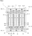
Fig. 2 ,RF battery system 1 usually comprises acell stack 2 formed of a plurality ofbattery cells 10 stacked together.Cell stack 2 comprises a stacked body that is formed by repeatedly stacking a cell frame 4,positive electrode 104,membrane 101, andnegative electrode 105 in this order. At both ends of the stacked body in the stacking direction, supply/drainage plates 20 are provided. To each supply/drainage plate 20,first pipe 107 andsecond pipe 108 offirst circulation mechanism 11, orfirst pipe 111 andsecond pipe 112 ofsecond circulation mechanism 12, are connected. The number ofbattery cells 10 stacked incell stack 2 can be selected as appropriate. - As illustrated in
Fig. 2 , cell frame 4 comprises a bipolar plate 41 and frame members 42. On one side of bipolar plate 41,positive electrode 104 is placed facing thereto. On the other side of bipolar plate 41,negative electrode 105 is placed facing thereto. Frame members 42 support the outer edges of bipolar plate 41. On the internal side of frame members 42,positive electrode 104 andnegative electrode 105 are accommodated sandwiching the bipolar plate 41.Positive electrode 104 andnegative electrode 105 sandwiching themembrane 101 are placed between bipolar plates 41 of two adjacent cell frames 4, to form asingle battery cell 10. -
RF battery system 1 according to the present example reduces problems that may occur withinbattery cell 10 due to a pressure difference between positive electrolyte 6 and negative electrolyte 7 circulating withinbattery cell 10. To reduce such problems, in the present example, the kinematic viscosity P1 of positive electrolyte 6 and the kinematic viscosity P2 of negative electrolyte 7 are adjusted. In the following, the configuration of positive electrolyte 6 and negative electrolyte 7 will be described in detail. An electrolyte 5 in the below description collectively refers to positive electrolyte 6 and negative electrolyte 7. - Positive electrolyte 6 includes a positive electrode active material. Negative electrolyte 7 includes a negative electrode active material. Typically, the positive electrode active material and the negative electrode active material are metal ions the valence of which changes along with oxidation and reduction. The positive electrode active material is vanadium (V) ions, iron (Fe) ions, copper (Cu) ions, or manganese (Mn) ions, for example. The negative electrode active material is V ions, chromium (Cr) ions, titanium (Ti) ions, cobalt (Co) ions, Cu ions, or zinc (Zn) ions, for example. A specific example involves a vanadium-based electrolyte where both the positive electrolyte 6 and the negative electrolyte 7 include V ions. Another specific example involves a manganese-titanium-based electrolyte where positive electrolyte 6 includes Mn ions and negative electrolyte 7 includes Ti ions.
- Electrolyte 5 of
RF battery system 1 according to the present example is a vanadium-based electrolyte. The concentration of the positive electrode active material in positive electrolyte 6 and the concentration of the negative electrode active material in negative electrolyte 7 are selected, as appropriate, to be suitable for the battery performance required ofRF battery system 1. In the vanadium-based electrolyte, the total concentration of vanadium ions as the positive electrode active material, more specifically, the total concentration of tetravalent vanadium ions and pentavalent vanadium ions is from 1.0 mol/liter to 3.0 mol/liter, for example. The total concentration of vanadium ions as the negative electrode active material, more specifically, the total concentration of divalent vanadium ions and trivalent vanadium ions is from 1.0 mol/liter to 3.0 mol/liter, for example. The lower limit to the concentration of each of the positive electrode active material and the negative electrode active material is a value that allows for ensuring a desired power output. Meanwhile, as described below, the positive electrode active material and the negative electrode active material cause an increase of the kinematic viscosity of electrolyte 5. When the kinematic viscosity of electrolyte 5 is too high, problems may occur during operation ofRF battery system 1. Because of this, the upper limit to the concentration of each of the positive electrode active material and the negative electrode active material is a value at which the kinematic viscosity of electrolyte 5 does not become too high. The concentration of the vanadium ions as the positive electrode active material may be 1.5 mol/liter or more, or 1.6 mol/liter or more, or 1.7 mol/liter or more, for example. The concentration of the vanadium ions as the negative electrode active material may be 1.5 mol/liter or more, or 1.6 mol/liter or more, or 1.7 mol/liter or more, for example. - Electrolyte 5 of
RF battery system 1 according to the above-mentioned another example is a Mn-Ti-based electrolyte. In this case, both the positive electrolyte 6 and the negative electrolyte 7 may include Mn ions and Ti ions. In positive electrolyte 6, Mn ions function as a positive electrode active material. In negative electrolyte 7, Ti ions function as a negative electrode active material. The standard oxidation-reduction potential of Mn ions is higher than the standard oxidation-reduction potential of other metal ions that are usable as a positive electrode active material. Therefore, a redox-flow battery system that includes Mn ions as a positive electrode active material and also includes Ti ions as a negative electrode active material has a high electromotive force. Mn is relatively inexpensive and readily available. Mn ions in positive electrolyte 6 sometimes become deposited as MnO2. Although the mechanism is not known, Ti ions included in positive electrolyte 6 reduce deposition of Mn ions. Neither Ti ions included in positive electrolyte 6 nor Mn ions included in negative electrolyte 7 function as an active material. Positive electrolyte 6 and negative electrolyte 7 of this type have the same composition before initial charging. Therefore, it is not necessary to individually prepare positive electrolyte 6 and negative electrolyte 7. - The concentration of the positive electrode active material in positive electrolyte 6 and the concentration of the negative electrode active material in negative electrolyte 7 are selected as appropriate to be suitable for the battery performance required of
RF battery system 1. In a Mn-Ti-based RF battery system, the concentration of the positive electrode active material, namely, the concentration of Mn ions is from 0.8 mol/liter to 1.2 mol/liter, for example. The concentration of the negative electrode active material, namely, the concentration of Ti ions is from 1.4 mol/liter to 1.9 mol/liter, for example. When the concentration of Mn ions and the concentration of Ti ions in the positive electrolyte do not exceed the upper limits of the above-mentioned ranges, respectively, the kinematic viscosity P1 of the positive electrolyte does not rise too high. When the concentration of Mn ions and the concentration of Ti ions in the negative electrolyte do not exceed the upper limits of the above-mentioned ranges, respectively, the kinematic viscosity P2 of the negative electrolyte does not rise too high. Therefore, a positive electrolyte having the concentration of Mn ions falling within the above-mentioned range and a negative electrolyte having the concentration of Ti ions falling within the above-mentioned range tend to have a ratio P1/P2 of their kinematic viscosity falling within the range of 0.70 to 0.97, or 1.05 to 1.30. Here, the lower limit to the concentration of each of the positive electrode active material and the negative electrode active material is a value that allows for ensuring a desired power output. Meanwhile, as described below, the positive electrode active material and the negative electrode active material cause an increase of the kinematic viscosity of electrolyte 5. When the kinematic viscosity of electrolyte 5 is too high, problems may occur during operation ofRF battery system 1. Because of this, the upper limit to the concentration of each of the positive electrode active material and the negative electrode active material is a value at which the kinematic viscosity of electrolyte 5 does not become too high. The concentration of Mn ions may be from 0.9 mol/liter to 1.1 mol/liter, for example. The concentration of Ti ions may be from 1.45 mol/liter from to 1.8 mol/liter, for example. - In addition to Mn ions and Ti ions, electrolyte 5 may include one or more types of ions selected from a first group consisting of magnesium (Mg) ions, cadmium (Cd) ions, tin (Sn) ions, indium (In) ions, antimony (Sb) ions, molybdenum (Mo) ions, cerium (Ce) ions, lead (Pb) ions, bismuth (Bi) ions, iron (Fe) ions, and ammonium (NH4) ions. The ions of the first group are different from the active material ions. When ions of the first group are included in electrolyte 5, aggregation of deposited MnO2 is reduced. The ions of the first group may be used for making fine adjustments of the viscosity of electrolyte 5.
- The total concentration of the ions of the first group is from 0.001 mol/liter to 1 mol/liter, for example. When the total concentration of the ions of the first group is 0.001 mol/liter or more, aggregation of deposited MnO2 tends to be reduced. When the concentration of the ions of the first group is 1 mol/liter or less, the kinematic viscosity of electrolyte 5 tends not to rise high. Further, the total concentration of the ions of the first group may be from 0.01 mol/liter to 0.5 mol/liter.
- Electrolyte 5 is an aqueous sulfuric acid (H2SO4) solution, an aqueous phosphoric acid (H3PO4) solution, and/or an aqueous nitric acid (HNO3) solution, for example. Sulfuric acid, phosphoric acid, and nitric acid cause an increase of the concentration of hydrogen ions which play a part in battery reactions. The aqueous sulfuric acid solution may include phosphoric acid. Electrolyte 5 according to the present example is an aqueous sulfuric acid solution including phosphoric acid. The concentration of sulfuric acid in the aqueous sulfuric acid solution is from 1.0 mol/liter to 6.0 mol/liter, for example. The higher the concentration of sulfuric acid included in electrolyte 5 is, the higher the kinematic viscosity of electrolyte 5 becomes. The concentration of sulfuric acid may be from 2.0 mol/liter to 5.0 mol/liter, or may be from 3.0 mol/liter to 4.0 mol/liter. Because the concentration of sulfuric acid affects the kinematic viscosity, it is desirable herein to adjust the concentration of sulfuric acid to fall within the above-mentioned range. The concentration of phosphoric acid in the aqueous sulfuric acid solution is from 0.1 mol/liter to 1.0 mol/liter, for example. The concentration of phosphoric acid may be from 0.15 mol/liter to 0.5 mol/liter, or may be from 0.2 mol/liter to 0.5 mol/liter, or may be from 0.25 mol/liter to 0.3 mol/liter.
- The concentration of ions of the elements included in electrolyte 5 is measured by inductively coupled plasma (ICP) atomic emission spectrometry, for example.
- The kinematic viscosity P1 of positive electrolyte 6 may change depending on the SOC of positive electrolyte 6. For example, in a Mn-Ti-based RF battery system where positive electrolyte 6 includes Mn ions as the positive electrode active material, along with an increase of the SOC of positive electrolyte 6, the concentration of Mn3+ in positive electrolyte 6 becomes higher than the concentration of Mn2+. As the SOC increases, the kinematic viscosity P1 may increase. The kinematic viscosity P2 of negative electrolyte 7 may change depending on the SOC of negative electrolyte 7. In the case where negative electrolyte 7 includes Ti ions as the negative electrode active material, along with an increase of the SOC of negative electrolyte 7, the concentration of Ti3+ in negative electrolyte 7 becomes higher than the concentration of Ti4+. As the SOC increases, the kinematic viscosity P2 may increase. Unlike the example of a Mn-Ti-based RF battery system, as the SOC of electrolyte 5 increases, the kinematic viscosity of electrolyte 5 may decrease. In a V-based RF battery system according to the present example, the kinematic viscosity of electrolyte 5 that includes V ions may decrease as the SOC increases. The kinematic viscosity P1, P2 is measured with a commercially available viscometer.
- When the difference between the kinematic viscosity P1 and the kinematic viscosity P2 is too large, there is a possibility that various problems can occur within
battery cell 10. For example, when the kinematic viscosity P1 is higher than the kinematic viscosity P2, the pressure of positive electrolyte 6 may become higher than the pressure of negative electrolyte 7. In this case, there is a possibility that a load can be applied onmembrane 101 by positive electrolyte 6 todamage membrane 101. In addition, positive electrolyte 6 can crushnegative electrode 105 to reduce the flowability of negative electrolyte 7 innegative electrode 105. Furthermore, when there are pinholes inmembrane 101, positive electrolyte 6 tends to flow through the pinholes to enter intonegative electrode cell 103. -
RF battery system 1 according to the present example is configured to operate in such a manner that the kinematic viscosity P1 and the kinematic viscosity P2 are different from each other. For example,RF battery system 1 may be configured to operate in such a manner that the ratio P1/P2 of the kinematic viscosity P1 to the kinematic viscosity P2 is from 0.70 to 0.97, or from 1.05 to 1.30. When the ratio P1/P2 falls within the above-mentioned range, the difference between the pressure of positive electrolyte 6 and the pressure of negative electrolyte 7 withinbattery cell 10 does not become too large. As a result,RF battery system 1 according to the present example is capable of reducing problems that can be caused by a pressure difference between positive electrolyte 6 and negative electrolyte 7. - When the ratio P1/P2 is close to 1, namely, when the difference between the kinematic viscosity P1 and the kinematic viscosity P2 is very small, diffusion at the contact interface between positive electrolyte 6 and negative electrolyte 7 tends to occur. As a result, when there are pinholes in
membrane 101, positive electrolyte 6 and negative electrolyte 7 with a ratio P1/P2 close to 1 tend to become mixed with each other once they pass through the pinholes. On the other hand, in the case of positive electrolyte 6 and negative electrolyte 7 with a ratio P1/P2 being 0.97 or less or 1.05 or more, the mixing rate tends to be low even when they pass through the pinholes. - As described above, as the ratio P1/P2 becomes closer to 1 or farther from 1, problems are more likely to occur. Therefore, the ratio P1/P2 may be from 0.80 to 0.96, or from 1.10 to 1.29, or from 0.90 to 0.96, or from 1.20 to 1.28, for example.
- The kinematic viscosity of electrolyte 5 rises depending on the concentration of the active material included in electrolyte 5, the concentration of sulfuric acid, and the like. Accordingly, to ensure the discharged capacity of
RF battery system 1 to be a certain value or more, the kinematic viscosity of electrolyte 5 needs to be equal to or more than a certain value. For example, the kinematic viscosity P1 of positive electrolyte 6 is 0.70×10⁻² cm2/s or more, or 1.0×10⁻² cm2/s or more, or 1.2×10⁻² cm2/s or more, or 2.0×10⁻² cm2/s or more, or 6.5×10⁻² cm2/s or more. The kinematic viscosity P2 of negative electrolyte 7 is, for example, 0.75×10⁻² cm2/s or more, or 0.95×10⁻² cm2/s or more, or 1.2×10⁻² cm2/s or more, or 1.9×10⁻² cm2/s or more, or 5.5×10⁻² cm2/s or more. - As the kinematic viscosity of electrolyte 5 increases, pressure loss of electrolyte 5 increases. As the pressure loss increases, power consumption of
pump - The range of the kinematic viscosity P1 may be from 1.0×10⁻² cm2/s to 20×10-2 cm2/s, or from 2.0×10⁻² cm2/s to 18×10-2 cm2/s, or from 6.5×10⁻² cm2/s to 9.7×10⁻² cm2/s, for example. As for a vanadium-based electrolyte, the range of the kinematic viscosity P1 may be from 0.70×10⁻² cm2/s to 5.0×10⁻² cm2/s, or from 1.0×10⁻² cm2/s to 5.0×10⁻² cm2/s, for example. The range of the kinematic viscosity P2 may be from 0.95×10⁻² cm2/s to 19×10-2 cm2/s, or from 1.9×10⁻² cm2/s to 17×10-2 cm2/s, or from 5.5×10⁻² cm2/s to 9.2×10⁻² cm2/s, for example. As for a vanadium-based electrolyte, the range of the kinematic viscosity P2 may be from 0.75×10⁻² cm2/s to 5.0×10⁻² cm2/s, or from 1.0×10⁻² cm2/s to 5.0×10⁻² cm2/s, for example.
- From the viewpoints of inhibiting degradation of electrolyte 5, enhancing battery efficiency, and the like,
RF battery system 1 is operated between the end-of-discharge voltage and the end-of-charge voltage. The end-of-discharge voltage is a voltage to stop discharging fromRF battery system 1 to power system 9. The end-of-charge voltage is a voltage to stop charging from power system 9 toRF battery system 1. As long asRF battery system 1 according to the present example is operated between the end-of-discharge voltage and the end-of-charge voltage, the ratio P1/P2 inRF battery system 1 satisfies the range of 0.70 to 0.97, or 1.05 to 1.30. The end-of-discharge voltage and the end-of-charge voltage are determined to be suitable for the properties of electrolyte 5, such as the type and concentration of the active material. - The end-of-discharge voltage and the end-of-charge voltage are measured with the use of a monitor cell, for example. An example of the configuration of the monitor cell is the same as that of
battery cell 10. The monitor cell may be one ofbattery cells 10 included incell stack 2, or may be abattery cell 10 that is not incell stack 2. - The end-of-discharge voltage and the end-of-charge voltage are determined in accordance with the charging molarity of the positive electrode active material in positive electrolyte 6 and the charging molarity of the negative electrode active material in negative electrolyte 7. The charging molarity is the molarity of active material ions that goes up during charging. In V-based
RF battery system 1 according to the present example, the charging molarity of the positive electrode active material is the molarity of V5+ in positive electrolyte 6, and the charging molarity of the negative electrode active material is the molarity of V2+. In Ti-Mn-basedRF battery system 1 according to the above-mentioned another example, the charging molarity of the positive electrode active material is the molarity of Mn3+ in positive electrolyte 6, and the charging molarity of the negative electrode active material is the molarity of Ti3+ in negative electrolyte 7. - The charging molarity of the active material can be converted into the SOC of electrolyte 5. Herein, the SOC of the positive electrolyte in V-based
RF battery system 1 is the ratio of V5+ ions to the V ions included in positive electrolyte 6, namely, (Concentration of V5+)/(Total concentration of V5+ and V4+). The SOC of the negative electrolyte in V-basedRF battery system 1 is the ratio of V2+ ions to the V ions included in negative electrolyte 7, namely, (Concentration of V2+)/(Total concentration of V2+ and V3+). The SOC of the positive electrolyte in Mn-Ti-basedRF battery system 1 is the ratio of Mn3+ to the Mn ions included in positive electrolyte 6, namely, (Concentration of Mn3+)/(Total concentration of Mn3+ and Mn2+). The SOC of the negative electrolyte in Mn-Ti-basedRF battery system 1 is the ratio of Ti3+ to the Ti ions included in negative electrolyte 7, namely, (Concentration of Ti3+)/(Total concentration of Ti3+ and Ti4+). - V-based
RF battery systems 1 of Sample No. I-1 to Sample No. I-3 were produced. Positive electrolyte 6 and negative electrolyte 7 of these samples were V-based electrolytes. Sample No. I-1 to Sample No. I-3 are different in the concentration of V ions and the concentration of sulfuric acid. In the present example, as for each sample, a trial calculation was made for the ratio P1/P2 of the kinematic viscosity P1 of the positive electrolyte to the kinematic viscosity P2 of the negative electrolyte during charge-discharge operation at a liquid temperature of 10°C, 30°C, or 50°C and at an SOC within the range of 0% to 100%. In the trial calculation, from the concentration of V ions and the concentration of sulfuric acid, the viscosity and the density of the positive electrolyte and the negative electrolyte at each temperature were calculated, and the resulting viscosity was divided by the density to calculate the kinematic viscosity. Then, the kinematic viscosity P1 of the positive electrolyte was divided by the kinematic viscosity P2 of the negative electrolyte to calculate the ratio P1/P2. - The concentration of V ions and the concentration of sulfuric acid in electrolyte 5 of Sample No. I-1 are as follows.
- ·Concentration of V ions: 1.7 mol/liter
- ·Concentration of sulfuric acid: 4.3 mol/liter
- Results of the test for Sample No. I-1 are shown in Table 1.
[Table 1] Sample No. I-1 (Concentration of V ions=1.7 mol/liter, Concentration of sulfuric acid=4.3 mol/liter) Test Example No. Temperature (°C) SOC (%) Kinematic viscosity (×10-2 cm2/s) Ratio P1/P2 Positive electrode P1 Negative electrode P2 I-1-1 30 0 2.36 2.78 0.850 I-1-2 30 50 2.12 2.48 0.857 I-1-3 30 100 1.88 2.17 0.868 I-1-4 50 0 1.48 1.69 0.875 I-1-5 50 50 1.25 1.42 0.884 I-1-6 50 100 1.02 1.14 0.899 I-1-7 10 0 4.40 4.69 0.937 I-1-8 10 50 3.89 4.43 0.877 I-1-9 10 100 3.37 4.16 0.810 - The concentration of V ions and the concentration of sulfuric acid in electrolyte 5 of Sample No. I-2 are as follows.
- ·Concentration of V ions: 1.3 mol/liter
- ·Concentration of sulfuric acid: 4.0 mol/liter
- Results of the test for Sample No. I-2 are shown in Table 2.
[Table 2] Sample No. I-2 (Concentration of V ions=1.3 mol/liter, Concentration of sulfuric acid=4.0 mol/liter) Test Example No. Temperature (°C) SOC (%) Kinematic viscosity (×10-2 cm2/s) Ratio P1/P2 Positive electrode P1 Negative electrode P2 I-2-1 30 0 1.88 2.11 0.893 I-2-2 30 50 1.63 1.80 0.909 I-2-3 30 100 1.38 1.48 0.934 I-2-4 50 0 1.12 1.34 0.834 I-2-5 50 50 1.00 1.15 0.869 I-2-6 50 100 0.88 0.96 0.921 I-2-7 10 0 3.43 3.85 0.891 I-2-8 10 50 3.18 3.53 0.902 I-2-9 10 100 2.94 3.20 0.917 - The concentration of V ions and the concentration of sulfuric acid in electrolyte 5 of Sample No. I-3 are as follows.
- ·Concentration of V ions: 1.0 mol/liter
- ·Concentration of sulfuric acid: 4.0 mol/liter
- Results of the test for Sample No. I-3 are shown in Table 3.
[Table 3] Sample No. I-3 (Concentration of V ions=1.0 mol/liter, Concentration of sulfuric acid=4.0 mol/liter) Test Example No. Temperature (°C) SOC (%) Kinematic viscosity (×10-2 cm2/s) Ratio P1/P2 Positive electrode P1 Negative electrode P2 I-3-1 30 0 1.66 1.78 0.929 I-3-2 30 50 1.42 1.55 0.918 I-3-3 30 100 1.19 1.31 0.904 I-3-4 50 0 1.09 1.16 0.940 I-3-5 50 50 0.94 1.01 0.932 I-3-6 50 100 0.80 0.87 0.922 I-3-7 10 0 2.85 3.13 0.912 I-3-8 10 50 2.62 3.01 0.871 I-3-9 10 100 2.40 2.90 0.827 - Referring to Table 1 to Table 3, in all the RF battery systems with the above-mentioned three compositions of V-based electrolyte, during charge-discharge operation at a liquid temperature of 10°C, 30°C, or 50°C and at an SOC within the range of 0% to 100%, the ratio P1/P2 of the kinematic viscosity P1 of the positive electrolyte to the kinematic viscosity P2 of the negative electrolyte is from 0.70 to 0.97 at all times during operation. From these results, it is presumed that when the end-of-discharge SOC and the end-of-charge SOC are set to fall within the range of 0% to 100% and the liquid temperature is set to fall within the range of 10°C to 50°C, the RF battery system in operation is capable of reliably maintaining the range of 0.70 to 0.97.
- Also referring to
Fig. 1 andFig. 2 , in the above-mentioned V-based electrolyte RF battery system, even when pinholes are formed inmembrane 101 ofbattery cell 10, diffusion of electrolyte 5 through the pinholes tends to be reduced, and, thereby, it is expected that the rate at which positive electrolyte 6 and negative electrolyte 7 are mixed with each other can be reduced. - As other examples,
RF battery systems 1 that included electrolytes 5 of Sample No. II-1 to Sample No. II-3, respectively, were produced. Positive electrolyte 6 and negative electrolyte 7 of these samples are Mn-Ti-based electrolytes. Before initial charging, the composition of positive electrolyte 6 is the same as the composition of negative electrolyte 7. After test operation ofRF battery system 1 of each sample which consisted of multiple sets of charging and discharging,RF battery system 1 was discharged until the end-of-discharge voltage was reached, and the kinematic viscosity of electrolyte 5 at the end-of-discharge voltage was measured. Then,RF battery system 1 of each sample was charged until the end-of-charge voltage was reached, and the kinematic viscosity of electrolyte 5 at the end-of-charge voltage was measured. The specifications of electrolyte 5 of each sample are described below. - The concentration of Mn ions, the concentration of Ti ions, and the concentration of sulfuric acid in electrolyte 5 of Sample No. II-1 are as follows. It should be noted that electrolyte 5 of the samples including Sample No. 1 includes phosphoric acid in a concentration selected from the range of 0.15 mol/liter to 0.30 mol/liter.
- ·Concentration of Mn ions: 1.1 mol/liter
- ·Concentration of Ti ions: 1.45 mol/liter
- ·Concentration of sulfuric acid: 5.35 mol/liter
- The end-of-discharge voltage is determined in advance based on the concentration of Mn ions and the concentration of Ti ions included in electrolyte 5. That is, the charging molarity of the positive electrode active material and the charging molarity of the negative electrode active material at the end-of-discharge voltage are also determined in advance. Similarly, the SOC of positive electrolyte 6 and the SOC of negative electrolyte 7 are also determined in advance. The charging molarity and the SOC at the end-of-discharge voltage are as follows.
- ·Charging molarity of positive electrode active material at end-of-discharge voltage, namely, concentration of Mn3+ in positive electrolyte 6: 0.35 mol/liter
- ·SOC of positive electrolyte 6 at end-of-discharge voltage, namely, 100×(Concentration of Mn3+)/(Concentration of Mn ions): About 32%
- ·Charging molarity of negative electrode active material at end-of-discharge voltage, namely, concentration of Ti3+ in negative electrolyte 7: 0.3 mol/liter
- ·SOC of negative electrolyte 7 at end-of-discharge voltage, namely, 100×(Concentration of Ti3+)/(Concentration of Ti ions): About 21%
- The end-of-charge voltage is determined in advance based on the concentration of Mn ions and the concentration of Ti ions included in electrolyte 5. That is, the charging molarity and the SOC are also determined in advance. The charging molarity and the SOC are as follows.
- ·Charging molarity of positive electrolyte 6 at end-of-charge voltage: 0.9 mol/liter
- ·SOC of positive electrolyte 6 at end-of-charge voltage: About 82%
- ·Charging molarity of negative electrolyte 7 at end-of-charge voltage: 1.0 mol/liter
- ·SOC of negative electrolyte 7 at end-of-charge voltage: About 69%
- The specifications of electrolyte 5 of Sample No. II-2 are as follows.
- ·Concentration of Mn ions in electrolyte 5: 1.1 mol/liter
- ·Concentration of Ti ions in electrolyte 5: 1.6 mol/liter
- ·Concentration of sulfuric acid in electrolyte 5: 5.5 mol/liter
- ·Charging molarity of positive electrode active material at end-of-discharge voltage: 0.35 mol/liter
- ·SOC of positive electrolyte 6 at end-of-discharge voltage: About 32%
- ·Charging molarity of negative electrode active material at end-of-discharge voltage: 0.3 mol/liter
- ·SOC of negative electrolyte 7 at end-of-discharge voltage: About 19%
- ·Charging molarity of positive electrode active material at end-of-charge voltage: 0.9 mol/liter
- ·SOC of positive electrolyte 6 at end-of-charge voltage: About 82%
- ·Charging molarity of positive electrode active material at end-of-charge voltage: 1.0 mol/liter
- ·SOC of negative electrolyte 7 at end-of-charge voltage: About 63%
- The specifications of electrolyte 5 of Sample No. II-3 are as follows.
- ·Concentration of Mn ions in electrolyte 5: 0.9 mol/liter
- ·Concentration of Ti ions in electrolyte 5: 1.8 mol/liter
- ·Concentration of sulfuric acid in electrolyte 5: 5.3 mol/liter
- ·Charging molarity of positive electrode active material at end-of-discharge voltage: 0.35 mol/liter
- ·SOC of positive electrolyte 6 at end-of-discharge voltage: About 39%
- ·Charging molarity of negative electrode active material at end-of-discharge voltage: 0.3 mol/liter
- ·SOC of negative electrolyte 7 at end-of-discharge voltage: About 17%
- ·Charging molarity of positive electrode active material at end-of-charge voltage: 1.0 mol/liter
- ·SOC of positive electrolyte 6 at end-of-charge voltage: About 100%
- ·Charging molarity of negative electrode active material at end-of-charge voltage: 1.5 mol/liter
- ·SOC of negative electrolyte 7 at end-of-charge voltage: About 83%
- It should be noted that two Mn2+ ions become Mn2+ and MnO2 by a disproportionated reaction. By this disproportionated reaction, the charging molarity of positive electrolyte 6 may become higher than the concentration of Mn ions.
-
RF battery system 1 of each sample was discharged until the end-of-discharge voltage was reached. The voltage ofRF battery system 1 was measured with the use of a monitor cell. FromRF battery system 1 that was discharged to the end-of-discharge voltage, positive electrolyte 6 and negative electrolyte 7 were sampled. The kinematic viscosity P1 of positive electrolyte 6 thus sampled and the kinematic viscosity P2 of negative electrolyte 7 are measured in accordance with JIS Z 8803. In this test, the kinematic viscosity P1, P2 was measured with a Cannon Fenske viscometer. The unit of the kinematic viscosity P1, P2 measured with the viscometer was cSt (centistokes). 1 cSt is 1×10⁻² cm2/s. For each sample, the charging molarity and the kinematic viscosity P1, P2 at the end-of-discharge voltage, as well as the charging molarity and the kinematic viscosity P1, P2 at the end-of-charge voltage are shown in Table 1. Moreover, in Table 4, the value of the ratio P1/P2 is shown.[Table 4] Sample No. Positive electrolyte Negative electrolyte Ratio P1/P2 Charging molarity (mol/liter) Kinematic viscosity P1 (×10-2 cm2/s) Charging molarity (mol/liter) Kinematic viscosity P2 (×10-2 cm2/s) II-1 End-of-discharge voltage 0.35 6.8 0.3 5.6 1.21 End-of-charge voltage 0.9 8.1 1.0 6.3 1.28 II-2 End-of-discharge voltage 0.35 8.7 0.3 6.9 1.26 End-of-charge voltage 0.9 9.6 1.0 7.4 1.29 II-3 End-of-discharge voltage 0.35 7.9 0.3 8.5 0.92 End-of-charge voltage 1.0 8.7 1.5 9.1 0.96 - Referring to Table 4, both the ratio P1/P2 of Sample No. II-1 and the ratio P1/P2 of Sample No. II-2 were from 1.05 to 1.30 at both the end-of-discharge voltage and the end-of-charge voltage.
RF battery system 1 is operated at between the end-of-discharge voltage and the end-of-charge voltage. Therefore, inRF battery system 1, the ratio P1/P2 of Sample No. II-1 and Sample No. II-2 satisfies the range of 1.05 to 1.30 at all times during operation. - P1/P2 of Sample No. II-3 was from 0.70 to 0.97 at both the end-of-discharge voltage and the end-of-charge voltage. Therefore, in
RF battery system 1, the ratio P1/P2 of Sample No. 3 satisfies the range of 0.70 to 0.97 at all times during operation. - In
RF battery system 1 of Sample No. II-1 to Sample No. II-3, even when pinholes are formed inmembrane 101 ofbattery cell 10, diffusion of electrolyte 5 through the pinholes tends to be reduced. Thereby, the rate at which positive electrolyte 6 and negative electrolyte 7 are mixed with each other can be reduced. - In Test Example II-2,
RF battery systems 1 of Sample No. II-1 and Sample No. II-2 were charged until a state of overcharge was reached. The charging molarity, the kinematic viscosity P1, P2, and the ratio P1/P2 of Sample No. II-1 and Sample No. II-2 at a state of overcharge are shown in Table 5.[Table 5] Sample No. Positive electrolyte Negative electrolyte Ratio P1/P2 Charging molarity (mol/liter) Kinematic viscosity P1 (×10-2 cm2/s) Charging molarity (mol/liter) Kinematic viscosity P2 (×10-2 cm2/s) II-1 1.05 8.5 1.2 6.4 1.31 II-2 1.05 9.85 1.2 7.5 1.31 - As for Sample No. II-1, the SOC of positive electrolyte 6 was 100×1.05/1.1=about 95%, and the SOC of negative electrolyte 7 was 100×1.2/1.45=about 83%. As for Sample No. II-2, the SOC of positive electrolyte 6 was 100×1.05/1.1=about 95%, and the SOC of negative electrolyte 7 was 100×1.2/1.6=about 75%. For both Sample No. II-1 and Sample No. II-2, the ratio P1/P2 was 1.31. It is conceivable that with the ratio P1/P2 exceeding 1.3, damage tends not to accumulate in
membrane 101. When pinholes are formed inmembrane 101, the pressure difference between electrolytes 5 increases, and, thereby, the high-pressure electrolyte 5 tends to flow through the pinholes to enter into the low-pressure electrolyte 5. - In Test Example II-3,
RF battery systems 1 of Sample No. II-1 and Sample No. II-2 were discharged until a state of overdischarge was reached. At a state of overdischarge, the charging molarity, the kinematic viscosity P1, P2, and the ratio P1/P2 of Sample No. II-1 and Sample No. II-2 are shown in Table 6.[Table 6] Sample No. Positive electrolyte Negative electrolyte Ratio P1/P2 Charging molarity (mol/liter) Kinematic viscosity P1 (×10-2 cm2/s) Charging molarity (mol/liter) Kinematic viscosity P2 (×10-2 cm2/s) II-1 0.08 6.4 0.07 6.2 1.04 II-2 0.1 6.3 0.05 6.1 1.04 - As for Sample No. II-1, the SOC of positive electrolyte 6 was 100×0.08/1.1=about 7%, and the SOC of negative electrolyte 7 was 100×0.07/1.45=about 5%. As for Sample No. II-2, the SOC of positive electrolyte 6 was 100×0.1/1.1=about 9%, and the SOC of negative electrolyte 7 was 100×0.05/1.6=about 3%. For both Sample No. 1 and Sample No. 2, the ratio P1/P2 was 1.04. It is conceivable that with the ratio P1/P2 exceeding 0.97 and below 1.05, damage tends not to accumulate in
membrane 101. However, when pinholes are formed inmembrane 101, surface tension tends not to act on parts of the pinholes where positive electrolyte 6 and negative electrolyte 7 are in contact with each other, and positive electrolyte 6 and negative electrolyte 7 tend to be mixed with each other. - 1 redox-flow battery system, 10 battery cell, 101 membrane, 102 positive electrode cell, 103 negative electrode cell, 104 positive electrode, 105 negative electrode, 11 first circulation mechanism, 106 tank, 107 first pipe, 108 second pipe, 109 pump, 12 second circulation mechanism, 110 tank, 111 first pipe, 112 second pipe, 113 pump, 2 cell stack, 20 supply/drainage plate, 4 cell frame, 41 bipolar plate, 42 frame member, 5 electrolyte, 6 positive electrolyte, 7 negative electrolyte, 8 electrode converter, 9 power system, 90 electric power generating unit, 91 transformer facility, 92 load.
Claims (6)
- A redox-flow battery system comprising:a battery cell;a positive electrolyte; anda negative electrolyte, whereinduring operation, a kinematic viscosity P1 of the positive electrolyte is different from a kinematic viscosity P2 of the negative electrolyte.
- The redox-flow battery system according to claim 1, wherein a ratio P1/P2 of the kinematic viscosity P1 to the kinematic viscosity P2 is from 0.70 to 0.97, or from 1.05 to 1.30.
- The redox-flow battery system according to claim 1 or 2, whereinthe kinematic viscosity P1 is from 0.70×10⁻² cm2/s to 20×10-2 cm2/s, andthe kinematic viscosity P2 is from 0.75×10⁻² cm2/s to 19×10-2 cm2/s.
- The redox-flow battery system according to any one of claims 1 to 3, wherein a positive electrode active material included in the positive electrolyte and a negative electrode active material included in the negative electrolyte are vanadium ions.
- The redox-flow battery system according to claim 4, wherein a concentration of the vanadium ions in each of the positive electrolyte and the negative electrolyte is from 1.0 mol/liter to 3.0 mol/liter.
- The redox-flow battery system according to any one of claims 1 to 5, whereineach of the positive electrolyte and the negative electrolyte is an aqueous sulfuric acid solution, andthe aqueous sulfuric acid solution has a concentration of sulfuric acid from 1.0 mol/liter to 6.0 mol/liter.
Applications Claiming Priority (2)
| Application Number | Priority Date | Filing Date | Title |
|---|---|---|---|
| JP2022129609 | 2022-08-16 | ||
| PCT/JP2023/026376 WO2024038726A1 (en) | 2022-08-16 | 2023-07-19 | Redox flow battery system |
Publications (2)
| Publication Number | Publication Date |
|---|---|
| EP4576287A1 true EP4576287A1 (en) | 2025-06-25 |
| EP4576287A4 EP4576287A4 (en) | 2026-04-01 |
Family
ID=89941480
Family Applications (1)
| Application Number | Title | Priority Date | Filing Date |
|---|---|---|---|
| EP23854763.2A Pending EP4576287A4 (en) | 2022-08-16 | 2023-07-19 | REDOX FLOW BATTERY SYSTEM |
Country Status (6)
| Country | Link |
|---|---|
| US (1) | US20260038854A1 (en) |
| EP (1) | EP4576287A4 (en) |
| JP (1) | JPWO2024038726A1 (en) |
| AU (1) | AU2023327164A1 (en) |
| TW (1) | TW202414877A (en) |
| WO (1) | WO2024038726A1 (en) |
Family Cites Families (7)
| Publication number | Priority date | Publication date | Assignee | Title |
|---|---|---|---|---|
| JP3601581B2 (en) * | 1999-06-11 | 2004-12-15 | 東洋紡績株式会社 | Carbon electrode material for vanadium redox flow battery |
| JP2003303611A (en) | 2002-04-10 | 2003-10-24 | Sumitomo Electric Ind Ltd | How to operate a redox flow battery |
| CA2748146C (en) | 2010-03-12 | 2012-10-02 | Sumitomo Electric Industries, Ltd. | Redox flow battery |
| WO2013051412A1 (en) * | 2011-10-04 | 2013-04-11 | 住友電気工業株式会社 | Cell frame, cell stack and redox flow battery |
| DE212015000116U1 (en) * | 2015-04-14 | 2016-12-19 | Sumitomo Electric Industries, Ltd. | Frame body, cell frame for a redox flow battery and redox flow battery |
| JP2019003871A (en) * | 2017-06-16 | 2019-01-10 | 株式会社ギャラキシー | Active material liquid and method of manufacturing active material liquid |
| JP7740881B2 (en) | 2021-02-25 | 2025-09-17 | 株式会社ミルボン | Composition and hair treatment method |
-
2023
- 2023-07-19 US US18/996,438 patent/US20260038854A1/en active Pending
- 2023-07-19 JP JP2024541464A patent/JPWO2024038726A1/ja active Pending
- 2023-07-19 WO PCT/JP2023/026376 patent/WO2024038726A1/en not_active Ceased
- 2023-07-19 EP EP23854763.2A patent/EP4576287A4/en active Pending
- 2023-07-19 AU AU2023327164A patent/AU2023327164A1/en active Pending
- 2023-08-07 TW TW112129523A patent/TW202414877A/en unknown
Also Published As
| Publication number | Publication date |
|---|---|
| TW202414877A (en) | 2024-04-01 |
| WO2024038726A1 (en) | 2024-02-22 |
| EP4576287A4 (en) | 2026-04-01 |
| AU2023327164A1 (en) | 2025-02-27 |
| US20260038854A1 (en) | 2026-02-05 |
| JPWO2024038726A1 (en) | 2024-02-22 |
Similar Documents
| Publication | Publication Date | Title |
|---|---|---|
| KR101178327B1 (en) | Redox flow battery | |
| CN101185185B (en) | Secondary battery, power supply system using same, and method for using power supply system | |
| US9853310B2 (en) | Distribution of electrolytes in a flow battery | |
| EP2387092A1 (en) | Redox flow battery | |
| EP2876718A1 (en) | Redox flow battery electrolyte and redox flow battery | |
| US11211635B2 (en) | Battery, battery pack, and uninterruptible power supply | |
| EP0165000B1 (en) | Metal-halogen secondary battery | |
| EP2876717A1 (en) | Electrolyte for redox flow battery and redox flow battery | |
| EP3358665B1 (en) | Power storage pack | |
| EP3480880A1 (en) | Redox flow battery, electrical quantity measurement system, and electrical quantity measurement method | |
| EP2876719A1 (en) | Electrolyte for redox flow battery and redox flow battery | |
| JP2012079678A (en) | Redox flow battery | |
| US10483567B2 (en) | Mechanical energy storage in flow batteries to enhance energy storage | |
| US12580209B2 (en) | Redox flow battery | |
| EP4576287A1 (en) | Redox flow battery system | |
| JP2011210696A (en) | Redox flow battery | |
| JP5489008B2 (en) | Redox flow battery | |
| JP4863172B2 (en) | Redox flow battery | |
| US20250030016A1 (en) | Battery with electrochemical cell | |
| EP4228039A1 (en) | Redox flow battery operation method , and redox flow battery system | |
| US20220384787A1 (en) | Aqueous rechargeable battery based on formation reaction anodes | |
| JP2011233373A (en) | Redox flow battery | |
| DE102015210752A1 (en) | Lithium oxygen cell cathode additives for quasi-constant voltage step | |
| KR100445709B1 (en) | Material with high performance and large capacity for secondary battery | |
| EP4002531A1 (en) | Redox flow battery cell, cell stack and redox flow battery system |
Legal Events
| Date | Code | Title | Description |
|---|---|---|---|
| STAA | Information on the status of an ep patent application or granted ep patent |
Free format text: STATUS: THE INTERNATIONAL PUBLICATION HAS BEEN MADE |
|
| PUAI | Public reference made under article 153(3) epc to a published international application that has entered the european phase |
Free format text: ORIGINAL CODE: 0009012 |
|
| STAA | Information on the status of an ep patent application or granted ep patent |
Free format text: STATUS: REQUEST FOR EXAMINATION WAS MADE |
|
| 17P | Request for examination filed |
Effective date: 20250213 |
|
| AK | Designated contracting states |
Kind code of ref document: A1 Designated state(s): AL AT BE BG CH CY CZ DE DK EE ES FI FR GB GR HR HU IE IS IT LI LT LU LV MC ME MK MT NL NO PL PT RO RS SE SI SK SM TR |
|
| DAV | Request for validation of the european patent (deleted) | ||
| DAX | Request for extension of the european patent (deleted) | ||
| A4 | Supplementary search report drawn up and despatched |
Effective date: 20260227 |
|
| RIC1 | Information provided on ipc code assigned before grant |
Ipc: H01M 8/18 20060101AFI20260223BHEP Ipc: H01M 8/02 20160101ALI20260223BHEP Ipc: H01M 8/04186 20160101ALI20260223BHEP Ipc: H01M 8/08 20160101ALI20260223BHEP |