EP3358665B1 - Power storage pack - Google Patents
Power storage pack Download PDFInfo
- Publication number
- EP3358665B1 EP3358665B1 EP16851455.2A EP16851455A EP3358665B1 EP 3358665 B1 EP3358665 B1 EP 3358665B1 EP 16851455 A EP16851455 A EP 16851455A EP 3358665 B1 EP3358665 B1 EP 3358665B1
- Authority
- EP
- European Patent Office
- Prior art keywords
- power storage
- pack
- charge
- storage pack
- curve
- Prior art date
- Legal status (The legal status is an assumption and is not a legal conclusion. Google has not performed a legal analysis and makes no representation as to the accuracy of the status listed.)
- Active
Links
- HBBGRARXTFLTSG-UHFFFAOYSA-N Lithium ion Chemical compound [Li+] HBBGRARXTFLTSG-UHFFFAOYSA-N 0.000 claims description 169
- 229910001416 lithium ion Inorganic materials 0.000 claims description 169
- 239000007773 negative electrode material Substances 0.000 claims description 70
- 239000007774 positive electrode material Substances 0.000 claims description 64
- 238000000034 method Methods 0.000 claims description 21
- 229910052987 metal hydride Inorganic materials 0.000 claims description 9
- 229910001367 Li3V2(PO4)3 Inorganic materials 0.000 claims description 8
- 229910052744 lithium Inorganic materials 0.000 claims description 8
- 230000008859 change Effects 0.000 claims description 7
- OKTJSMMVPCPJKN-UHFFFAOYSA-N Carbon Chemical compound [C] OKTJSMMVPCPJKN-UHFFFAOYSA-N 0.000 description 44
- 229910002804 graphite Inorganic materials 0.000 description 44
- 239000010439 graphite Substances 0.000 description 44
- 239000011572 manganese Substances 0.000 description 37
- 229910002986 Li4Ti5O12 Inorganic materials 0.000 description 30
- 229910052493 LiFePO4 Inorganic materials 0.000 description 27
- 229910002097 Lithium manganese(III,IV) oxide Inorganic materials 0.000 description 21
- XOLBLPGZBRYERU-UHFFFAOYSA-N tin dioxide Chemical compound O=[Sn]=O XOLBLPGZBRYERU-UHFFFAOYSA-N 0.000 description 18
- 238000010586 diagram Methods 0.000 description 15
- -1 transition metal sulfide Chemical class 0.000 description 12
- 229910021470 non-graphitizable carbon Inorganic materials 0.000 description 11
- 230000009467 reduction Effects 0.000 description 11
- 229910052723 transition metal Inorganic materials 0.000 description 10
- 229910001228 Li[Ni1/3Co1/3Mn1/3]O2 (NCM 111) Inorganic materials 0.000 description 9
- 230000006866 deterioration Effects 0.000 description 9
- LIVNPJMFVYWSIS-UHFFFAOYSA-N silicon monoxide Chemical compound [Si-]#[O+] LIVNPJMFVYWSIS-UHFFFAOYSA-N 0.000 description 8
- NUJOXMJBOLGQSY-UHFFFAOYSA-N manganese dioxide Chemical compound O=[Mn]=O NUJOXMJBOLGQSY-UHFFFAOYSA-N 0.000 description 6
- 239000003990 capacitor Substances 0.000 description 5
- 229910021385 hard carbon Inorganic materials 0.000 description 5
- 229910011279 LiCoPO4 Inorganic materials 0.000 description 4
- WHXSMMKQMYFTQS-UHFFFAOYSA-N Lithium Chemical compound [Li] WHXSMMKQMYFTQS-UHFFFAOYSA-N 0.000 description 4
- GWEVSGVZZGPLCZ-UHFFFAOYSA-N Titan oxide Chemical compound O=[Ti]=O GWEVSGVZZGPLCZ-UHFFFAOYSA-N 0.000 description 4
- 239000002131 composite material Substances 0.000 description 4
- QXYJCZRRLLQGCR-UHFFFAOYSA-N dioxomolybdenum Chemical compound O=[Mo]=O QXYJCZRRLLQGCR-UHFFFAOYSA-N 0.000 description 4
- GNTDGMZSJNCJKK-UHFFFAOYSA-N divanadium pentaoxide Chemical compound O=[V](=O)O[V](=O)=O GNTDGMZSJNCJKK-UHFFFAOYSA-N 0.000 description 4
- 150000002484 inorganic compounds Chemical class 0.000 description 4
- 229910010272 inorganic material Inorganic materials 0.000 description 4
- 239000000203 mixture Substances 0.000 description 4
- 150000002894 organic compounds Chemical class 0.000 description 4
- 150000003624 transition metals Chemical class 0.000 description 4
- 229910000668 LiMnPO4 Inorganic materials 0.000 description 3
- 229910003932 NixMnyCozO2 Inorganic materials 0.000 description 3
- 239000000956 alloy Substances 0.000 description 3
- 238000007600 charging Methods 0.000 description 3
- 230000007246 mechanism Effects 0.000 description 3
- 230000004048 modification Effects 0.000 description 3
- 238000012986 modification Methods 0.000 description 3
- 229910021384 soft carbon Inorganic materials 0.000 description 3
- HEZMWWAKWCSUCB-PHDIDXHHSA-N (3R,4R)-3,4-dihydroxycyclohexa-1,5-diene-1-carboxylic acid Chemical compound O[C@@H]1C=CC(C(O)=O)=C[C@H]1O HEZMWWAKWCSUCB-PHDIDXHHSA-N 0.000 description 2
- PXLYGWXKAVCTPX-UHFFFAOYSA-N 1,2,3,4,5,6-hexamethylidenecyclohexane Chemical class C=C1C(=C)C(=C)C(=C)C(=C)C1=C PXLYGWXKAVCTPX-UHFFFAOYSA-N 0.000 description 2
- 229910012652 LiCo1 Inorganic materials 0.000 description 2
- 229910032387 LiCoO2 Inorganic materials 0.000 description 2
- 229910011623 LiCrTiO4 Inorganic materials 0.000 description 2
- 229910010759 LiFeTiO4 Inorganic materials 0.000 description 2
- 229910016765 Ni0.5Mn1.5 Inorganic materials 0.000 description 2
- VYPSYNLAJGMNEJ-UHFFFAOYSA-N Silicium dioxide Chemical compound O=[Si]=O VYPSYNLAJGMNEJ-UHFFFAOYSA-N 0.000 description 2
- QAOWNCQODCNURD-UHFFFAOYSA-N Sulfuric acid Chemical compound OS(O)(=O)=O QAOWNCQODCNURD-UHFFFAOYSA-N 0.000 description 2
- 239000011149 active material Substances 0.000 description 2
- 230000015572 biosynthetic process Effects 0.000 description 2
- 239000003575 carbonaceous material Substances 0.000 description 2
- 150000001875 compounds Chemical class 0.000 description 2
- 230000000593 degrading effect Effects 0.000 description 2
- 125000005331 diazinyl group Chemical class N1=NC(=CC=C1)* 0.000 description 2
- 238000007599 discharging Methods 0.000 description 2
- 150000002019 disulfides Chemical class 0.000 description 2
- OAEGRYMCJYIXQT-UHFFFAOYSA-N dithiooxamide Chemical class NC(=S)C(N)=S OAEGRYMCJYIXQT-UHFFFAOYSA-N 0.000 description 2
- 239000008151 electrolyte solution Substances 0.000 description 2
- 229910044991 metal oxide Inorganic materials 0.000 description 2
- 150000004706 metal oxides Chemical class 0.000 description 2
- 150000004053 quinones Chemical class 0.000 description 2
- 238000003786 synthesis reaction Methods 0.000 description 2
- 229910000314 transition metal oxide Inorganic materials 0.000 description 2
- ZNOKGRXACCSDPY-UHFFFAOYSA-N tungsten(VI) oxide Inorganic materials O=[W](=O)=O ZNOKGRXACCSDPY-UHFFFAOYSA-N 0.000 description 2
- 229910007404 Li2Ti3O7 Inorganic materials 0.000 description 1
- 229910002993 LiMnO2 Inorganic materials 0.000 description 1
- 229910003005 LiNiO2 Inorganic materials 0.000 description 1
- 229910013084 LiNiPO4 Inorganic materials 0.000 description 1
- 229910013124 LiNiVO4 Inorganic materials 0.000 description 1
- 229910012999 LiVOPO4 Inorganic materials 0.000 description 1
- 230000005856 abnormality Effects 0.000 description 1
- 229910045601 alloy Inorganic materials 0.000 description 1
- 238000006243 chemical reaction Methods 0.000 description 1
- 239000007795 chemical reaction product Substances 0.000 description 1
- 229910052804 chromium Inorganic materials 0.000 description 1
- 229910052681 coesite Inorganic materials 0.000 description 1
- 238000010277 constant-current charging Methods 0.000 description 1
- 230000007797 corrosion Effects 0.000 description 1
- 238000005260 corrosion Methods 0.000 description 1
- 229910052906 cristobalite Inorganic materials 0.000 description 1
- 230000001419 dependent effect Effects 0.000 description 1
- 238000005868 electrolysis reaction Methods 0.000 description 1
- 239000000446 fuel Substances 0.000 description 1
- 229910021469 graphitizable carbon Inorganic materials 0.000 description 1
- 239000012212 insulator Substances 0.000 description 1
- PIJPYDMVFNTHIP-UHFFFAOYSA-L lead sulfate Chemical compound [PbH4+2].[O-]S([O-])(=O)=O PIJPYDMVFNTHIP-UHFFFAOYSA-L 0.000 description 1
- FRMOHNDAXZZWQI-UHFFFAOYSA-N lithium manganese(2+) nickel(2+) oxygen(2-) Chemical compound [O-2].[Mn+2].[Ni+2].[Li+] FRMOHNDAXZZWQI-UHFFFAOYSA-N 0.000 description 1
- 229910052748 manganese Inorganic materials 0.000 description 1
- 239000000463 material Substances 0.000 description 1
- 229910052751 metal Inorganic materials 0.000 description 1
- 239000002184 metal Substances 0.000 description 1
- 229910052759 nickel Inorganic materials 0.000 description 1
- 239000011255 nonaqueous electrolyte Substances 0.000 description 1
- 238000002360 preparation method Methods 0.000 description 1
- 230000001172 regenerating effect Effects 0.000 description 1
- 230000008929 regeneration Effects 0.000 description 1
- 238000011069 regeneration method Methods 0.000 description 1
- 239000000377 silicon dioxide Substances 0.000 description 1
- 229910052682 stishovite Inorganic materials 0.000 description 1
- 238000006467 substitution reaction Methods 0.000 description 1
- 229910052718 tin Inorganic materials 0.000 description 1
- 230000007723 transport mechanism Effects 0.000 description 1
- 229910052905 tridymite Inorganic materials 0.000 description 1
Images


Classifications
-
- H—ELECTRICITY
- H01—ELECTRIC ELEMENTS
- H01M—PROCESSES OR MEANS, e.g. BATTERIES, FOR THE DIRECT CONVERSION OF CHEMICAL ENERGY INTO ELECTRICAL ENERGY
- H01M10/00—Secondary cells; Manufacture thereof
- H01M10/42—Methods or arrangements for servicing or maintenance of secondary cells or secondary half-cells
- H01M10/44—Methods for charging or discharging
- H01M10/441—Methods for charging or discharging for several batteries or cells simultaneously or sequentially
-
- H—ELECTRICITY
- H01—ELECTRIC ELEMENTS
- H01M—PROCESSES OR MEANS, e.g. BATTERIES, FOR THE DIRECT CONVERSION OF CHEMICAL ENERGY INTO ELECTRICAL ENERGY
- H01M10/00—Secondary cells; Manufacture thereof
- H01M10/05—Accumulators with non-aqueous electrolyte
- H01M10/052—Li-accumulators
- H01M10/0525—Rocking-chair batteries, i.e. batteries with lithium insertion or intercalation in both electrodes; Lithium-ion batteries
-
- H—ELECTRICITY
- H01—ELECTRIC ELEMENTS
- H01M—PROCESSES OR MEANS, e.g. BATTERIES, FOR THE DIRECT CONVERSION OF CHEMICAL ENERGY INTO ELECTRICAL ENERGY
- H01M10/00—Secondary cells; Manufacture thereof
- H01M10/05—Accumulators with non-aqueous electrolyte
- H01M10/058—Construction or manufacture
-
- H—ELECTRICITY
- H01—ELECTRIC ELEMENTS
- H01M—PROCESSES OR MEANS, e.g. BATTERIES, FOR THE DIRECT CONVERSION OF CHEMICAL ENERGY INTO ELECTRICAL ENERGY
- H01M10/00—Secondary cells; Manufacture thereof
- H01M10/42—Methods or arrangements for servicing or maintenance of secondary cells or secondary half-cells
- H01M10/44—Methods for charging or discharging
-
- H—ELECTRICITY
- H01—ELECTRIC ELEMENTS
- H01M—PROCESSES OR MEANS, e.g. BATTERIES, FOR THE DIRECT CONVERSION OF CHEMICAL ENERGY INTO ELECTRICAL ENERGY
- H01M16/00—Structural combinations of different types of electrochemical generators
-
- H—ELECTRICITY
- H01—ELECTRIC ELEMENTS
- H01M—PROCESSES OR MEANS, e.g. BATTERIES, FOR THE DIRECT CONVERSION OF CHEMICAL ENERGY INTO ELECTRICAL ENERGY
- H01M4/00—Electrodes
- H01M4/02—Electrodes composed of, or comprising, active material
- H01M4/13—Electrodes for accumulators with non-aqueous electrolyte, e.g. for lithium-accumulators; Processes of manufacture thereof
- H01M4/131—Electrodes based on mixed oxides or hydroxides, or on mixtures of oxides or hydroxides, e.g. LiCoOx
-
- H—ELECTRICITY
- H01—ELECTRIC ELEMENTS
- H01M—PROCESSES OR MEANS, e.g. BATTERIES, FOR THE DIRECT CONVERSION OF CHEMICAL ENERGY INTO ELECTRICAL ENERGY
- H01M4/00—Electrodes
- H01M4/02—Electrodes composed of, or comprising, active material
- H01M4/36—Selection of substances as active materials, active masses, active liquids
- H01M4/362—Composites
- H01M4/364—Composites as mixtures
-
- H—ELECTRICITY
- H01—ELECTRIC ELEMENTS
- H01M—PROCESSES OR MEANS, e.g. BATTERIES, FOR THE DIRECT CONVERSION OF CHEMICAL ENERGY INTO ELECTRICAL ENERGY
- H01M4/00—Electrodes
- H01M4/02—Electrodes composed of, or comprising, active material
- H01M4/36—Selection of substances as active materials, active masses, active liquids
- H01M4/48—Selection of substances as active materials, active masses, active liquids of inorganic oxides or hydroxides
- H01M4/50—Selection of substances as active materials, active masses, active liquids of inorganic oxides or hydroxides of manganese
- H01M4/505—Selection of substances as active materials, active masses, active liquids of inorganic oxides or hydroxides of manganese of mixed oxides or hydroxides containing manganese for inserting or intercalating light metals, e.g. LiMn2O4 or LiMn2OxFy
-
- H—ELECTRICITY
- H01—ELECTRIC ELEMENTS
- H01M—PROCESSES OR MEANS, e.g. BATTERIES, FOR THE DIRECT CONVERSION OF CHEMICAL ENERGY INTO ELECTRICAL ENERGY
- H01M4/00—Electrodes
- H01M4/02—Electrodes composed of, or comprising, active material
- H01M4/36—Selection of substances as active materials, active masses, active liquids
- H01M4/48—Selection of substances as active materials, active masses, active liquids of inorganic oxides or hydroxides
- H01M4/52—Selection of substances as active materials, active masses, active liquids of inorganic oxides or hydroxides of nickel, cobalt or iron
- H01M4/525—Selection of substances as active materials, active masses, active liquids of inorganic oxides or hydroxides of nickel, cobalt or iron of mixed oxides or hydroxides containing iron, cobalt or nickel for inserting or intercalating light metals, e.g. LiNiO2, LiCoO2 or LiCoOxFy
-
- H—ELECTRICITY
- H01—ELECTRIC ELEMENTS
- H01M—PROCESSES OR MEANS, e.g. BATTERIES, FOR THE DIRECT CONVERSION OF CHEMICAL ENERGY INTO ELECTRICAL ENERGY
- H01M4/00—Electrodes
- H01M4/02—Electrodes composed of, or comprising, active material
- H01M4/36—Selection of substances as active materials, active masses, active liquids
- H01M4/58—Selection of substances as active materials, active masses, active liquids of inorganic compounds other than oxides or hydroxides, e.g. sulfides, selenides, tellurides, halogenides or LiCoFy; of polyanionic structures, e.g. phosphates, silicates or borates
- H01M4/5825—Oxygenated metallic salts or polyanionic structures, e.g. borates, phosphates, silicates, olivines
-
- H—ELECTRICITY
- H01—ELECTRIC ELEMENTS
- H01M—PROCESSES OR MEANS, e.g. BATTERIES, FOR THE DIRECT CONVERSION OF CHEMICAL ENERGY INTO ELECTRICAL ENERGY
- H01M50/00—Constructional details or processes of manufacture of the non-active parts of electrochemical cells other than fuel cells, e.g. hybrid cells
- H01M50/20—Mountings; Secondary casings or frames; Racks, modules or packs; Suspension devices; Shock absorbers; Transport or carrying devices; Holders
- H01M50/204—Racks, modules or packs for multiple batteries or multiple cells
-
- H—ELECTRICITY
- H02—GENERATION; CONVERSION OR DISTRIBUTION OF ELECTRIC POWER
- H02J—CIRCUIT ARRANGEMENTS OR SYSTEMS FOR SUPPLYING OR DISTRIBUTING ELECTRIC POWER; SYSTEMS FOR STORING ELECTRIC ENERGY
- H02J7/00—Circuit arrangements for charging or depolarising batteries or for supplying loads from batteries
-
- H—ELECTRICITY
- H01—ELECTRIC ELEMENTS
- H01M—PROCESSES OR MEANS, e.g. BATTERIES, FOR THE DIRECT CONVERSION OF CHEMICAL ENERGY INTO ELECTRICAL ENERGY
- H01M10/00—Secondary cells; Manufacture thereof
- H01M10/06—Lead-acid accumulators
-
- H—ELECTRICITY
- H01—ELECTRIC ELEMENTS
- H01M—PROCESSES OR MEANS, e.g. BATTERIES, FOR THE DIRECT CONVERSION OF CHEMICAL ENERGY INTO ELECTRICAL ENERGY
- H01M10/00—Secondary cells; Manufacture thereof
- H01M10/34—Gastight accumulators
- H01M10/345—Gastight metal hydride accumulators
-
- Y—GENERAL TAGGING OF NEW TECHNOLOGICAL DEVELOPMENTS; GENERAL TAGGING OF CROSS-SECTIONAL TECHNOLOGIES SPANNING OVER SEVERAL SECTIONS OF THE IPC; TECHNICAL SUBJECTS COVERED BY FORMER USPC CROSS-REFERENCE ART COLLECTIONS [XRACs] AND DIGESTS
- Y02—TECHNOLOGIES OR APPLICATIONS FOR MITIGATION OR ADAPTATION AGAINST CLIMATE CHANGE
- Y02E—REDUCTION OF GREENHOUSE GAS [GHG] EMISSIONS, RELATED TO ENERGY GENERATION, TRANSMISSION OR DISTRIBUTION
- Y02E60/00—Enabling technologies; Technologies with a potential or indirect contribution to GHG emissions mitigation
- Y02E60/10—Energy storage using batteries
-
- Y—GENERAL TAGGING OF NEW TECHNOLOGICAL DEVELOPMENTS; GENERAL TAGGING OF CROSS-SECTIONAL TECHNOLOGIES SPANNING OVER SEVERAL SECTIONS OF THE IPC; TECHNICAL SUBJECTS COVERED BY FORMER USPC CROSS-REFERENCE ART COLLECTIONS [XRACs] AND DIGESTS
- Y02—TECHNOLOGIES OR APPLICATIONS FOR MITIGATION OR ADAPTATION AGAINST CLIMATE CHANGE
- Y02P—CLIMATE CHANGE MITIGATION TECHNOLOGIES IN THE PRODUCTION OR PROCESSING OF GOODS
- Y02P70/00—Climate change mitigation technologies in the production process for final industrial or consumer products
- Y02P70/50—Manufacturing or production processes characterised by the final manufactured product
-
- Y—GENERAL TAGGING OF NEW TECHNOLOGICAL DEVELOPMENTS; GENERAL TAGGING OF CROSS-SECTIONAL TECHNOLOGIES SPANNING OVER SEVERAL SECTIONS OF THE IPC; TECHNICAL SUBJECTS COVERED BY FORMER USPC CROSS-REFERENCE ART COLLECTIONS [XRACs] AND DIGESTS
- Y02—TECHNOLOGIES OR APPLICATIONS FOR MITIGATION OR ADAPTATION AGAINST CLIMATE CHANGE
- Y02T—CLIMATE CHANGE MITIGATION TECHNOLOGIES RELATED TO TRANSPORTATION
- Y02T10/00—Road transport of goods or passengers
- Y02T10/60—Other road transportation technologies with climate change mitigation effect
- Y02T10/70—Energy storage systems for electromobility, e.g. batteries
Definitions
- the present invention relates to a power storage pack.
- Lead storage batteries are widely used in various applications, such as in-car applications for driving automobiles or for use as power supply to various types of electric loads, industrial applications for use as backup power supplies for commercial power supplies, and electric vehicle applications for use as main power supplies for golf carts, forklifts, and the like.
- Lead storage batteries are commonly used, such as six batteries connected in series for 12 V, and batteries configured for 24 V, 36 V, 48 V, 60 V, 72 V, and the like as multiples of 12 V.
- Lead storage batteries are low in price as compared with storage batteries such as lithium ion storage batteries and nickel-metal-hydride storage batteries, but inferior in charge/discharge cycle characteristics as compared with the storage batteries.
- lead storage batteries have charge/discharge cycle characteristics degraded significantly on reaching an overcharge state or an overdischarge state. For example, when a lead storage battery reaches an overcharge state, gas generation and a decrease in amount of electrolytic solution, corrosion of a current collector, and loss of an active material due to electrolysis of sulfuric acid as an electrolytic solution will be caused, thereby degrading charge/discharge cycle characteristics.
- Japanese Patent Application 2007-131134 proposes a power storage system where an inexpensive lead storage battery and a high-performance storage battery which is superior in charge/discharge cycle characteristics to the lead storage battery are connected in parallel.
- the DC-DC converter is high in price and large in size, and the power storage system described in JP2007-131134 , which is provided with the DC-DC converter, is thus high in price and large in size.
- US 2011/086248 discloses an assembled battery including a combination of two kinds of secondary batteries differing in battery property (charge voltage behavior), each secondary battery including a positive electrode, a negative electrode, a separator interposed between the positive and negative electrodes, and a non-aqueous electrolyte.
- US 2011/086248 relates to an assembled battery including at least one first cell and at least one second cell electrically connected in series. The second cell has a greater change in charge voltage at the end of charge and a larger cell capacity.
- EP3223336 discloses an on-vehicle battery including a lead storage battery and a second storage battery.
- the second storage battery is connected in parallel with the lead storage battery.
- the second storage battery has a positive electrode and a negative electrode.
- the positive electrode includes, as a positive electrode active material, a spinel-type lithium-nickel-manganese oxide.
- the negative electrode includes, as a negative electrode active material, at least one of graphite, soft carbon, hard carbon, and an alloy-based material containing an Si element.
- a first power storage pack according to the present invention is for connection in parallel with a second power storage pack with a different battery chemistry and without any DC-DC converter interposed between the first power storage pack and the second power storage pack.
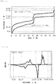
- a charge/discharge curve of the first power storage pack measured with a constant C-rate has a step passing through a range of (12.5 ⁇ n) V or higher and (12.8 ⁇ n) V or lower, where n is a natural number of 1 or more and 125 or less.
- an average discharge voltage falls within a range of (9.0 ⁇ n) V or higher and (12.5 ⁇ n) V or lower and/or a voltage at a peak top obtained on a dQ/dV curve obtained by differentiating the discharge curve with respect to voltage falls within a range of (9.0 ⁇ n) V or higher and (12.5 ⁇ n) V or lower.
- an average charge voltage falls within the range of (12.8 ⁇ n) V or higher and (14.8 ⁇ n) V or lower and/or a voltage at a peak top obtained on a dQ/dV curve obtained by differentiating the charge curve with respect to voltage falls within the range of (12.8 ⁇ n) V or higher and (14.8 ⁇ n) V or lower.
- a step of a charge or discharge curve refers to a range in which the proportion of the amount of change in voltage, ⁇ V, on the charge/discharge curve to the amount of change in SOC, ⁇ SOC, is (100 ⁇ n) mV/% or more, when the SOC is in the range of 5% to 95%.
- the start point of a step is the minimum voltage of a discharge curve in the range of one step, and the corresponding value of the SOC at the minimum voltage
- the end point of the step is the maximum voltage of a charge curve in the range of the same step, and the corresponding value of the SOC at the maximum voltage.
- the first power storage pack according to the present invention connected in parallel to a second power storage pack with 6 ⁇ n lead storage batteries connected in series.
- the second power storage pack with the 6 ⁇ n lead storage batteries connected in series represents a lead storage battery pack configured for a multiple of 12 V.
- the second power storage pack with the 6 ⁇ n lead storage batteries connected in series represents a lead storage battery pack configured for 12 V with six lead storage batteries connected in series.
- the second power storage pack with the 6 ⁇ n lead storage batteries connected in series represents a lead storage battery pack configured for 24 V with twelve lead storage batteries connected in series, or a lead storage battery pack configured for 24 V with two series-connected lead storage batteries each configured for 12 V.
- n 3 or more.
- the first power storage pack according to the present invention has a step passing through the range of (12.5 ⁇ n) V or higher and (12.8 ⁇ n) V or lower (n is a natural number of 1 or more and 125 or less). For this reason, for example, in a power storage system in which a second power storage pack with 6 ⁇ n lead storage batteries connected in series is connected in parallel to the first power storage pack according to the present invention, when the voltage of the lead storage battery pack falls within the voltage range in normal use, the voltage of the first power storage pack according to the present invention substantially coincides with the voltage of the lead storage battery pack at the step of the charge/discharge curve for the first power storage pack according to the present invention.
- the generation of a large voltage difference is eliminated between the power storage pack according to the present invention and the lead storage battery pack. Therefore, there is not always a need to provide a DC-DC converter between the first power storage pack according to the present invention and the lead storage battery pack. Accordingly, for example, the use of the first power storage pack according to the present invention makes it possible to reduce the price of a power storage system including the lead storage battery pack, and reduce the size thereof.
- the average discharge voltage on the lower SOC side than the start point of the step of the charge/discharge curve for the first power storage pack according to the present invention falls within the range of (9.0 ⁇ n) V or higher and (12.5 ⁇ n) V or lower. For this reason, when the power storage system with the parallel-connected power storage packs each with the 6 ⁇ n lead storage batteries connected in series is required for large current output, the output from the power storage packs according to the present invention is also provided in a condition in which the voltage of the lead storage battery pack is lower than the voltage range in normal use, thereby making it possible to prevent the voltage of the lead storage battery pack from being lower than the discharge cutoff voltage.
- the average charge voltage on the higher SOC side than the end point of the step of the charge/discharge curve for the first power storage pack according to the present invention falls within the range of (12.8 ⁇ n) V or higher and (14.8 ⁇ n) V or lower. For this reason, when the power storage system with the parallel-connected power storage packs each with the 6 ⁇ n lead storage batteries connected in series is required for large current input, the input to the power storage packs according to the present invention is also provided in a condition in which the voltage of the lead storage battery pack is higher than the voltage range in normal use, thereby making it possible to prevent the voltage of the lead storage battery pack from being higher than the charge cutoff voltage.
- the charge/discharge curve for a first power storage pack according to the present invention has a step passing through the range of (12.5 ⁇ n) V or higher and (12.8 ⁇ n) V or lower (n is a natural number of 1 or more and 125 or less).
- n is a natural number of 1 or more and 125 or less.
- the voltage at the peak top obtained on the curve (dQ/dV curve) obtained by differentiating, with respect to voltage, the discharge curve for the first power storage pack falls within the range of (9.0 ⁇ n) V or higher and (12.5 ⁇ n) V or lower.
- the voltage at the peak top obtained on the curve (dQ/dV curve) obtained by differentiating, with respect to voltage, the charge curve for the first power storage pack falls within the range of (12.8 ⁇ n) V or higher and (14.8 ⁇ n) V or lower.
- the first power storage pack according to the present invention connected in parallel to a second power storage pack with 6 ⁇ n lead storage batteries connected in series.
- the first power storage pack according to the present invention has a step passing through the range of (12.5 ⁇ n) V or higher and (12.8 ⁇ n) V or lower (n is a natural number of 1 or more and 125 or less). For this reason, for example, in a power storage system in which a second power storage pack with 6 ⁇ n lead storage batteries connected in series is connected in parallel to the first power storage pack according to the present invention, when the voltage of the lead storage battery pack falls within the voltage range in normal use, the voltage of the first power storage pack according to the present invention substantially coincides with the voltage of the lead storage battery pack at the step of the charge/discharge curve for the first power storage pack according to the present invention.
- the use of the first power storage pack according to the present invention makes it possible to reduce the price of a power storage system including the lead storage battery pack, and reduce the size thereof.
- the voltage at the peak top obtained on the curve (dQ/dV curve) obtained by differentiating, with respect to voltage, the discharge curve for the first power storage pack falls within the range of (9.0 ⁇ n) V or higher and (12.5 ⁇ n) V or lower.
- the output from the power storage packs according to the present invention is also provided in a condition in which the voltage of the lead storage battery pack is lower than the voltage range in normal use, thereby making it possible to prevent the voltage of the lead storage battery pack from being lower than the discharge cutoff voltage. Therefore, deterioration due to an overdischarge state of the lead storage battery pack can be prevented, thereby allowing an increase in the life-span of the power storage system. In addition, there is no need for a special circuit for preventing an overdischarge state of the lead storage battery pack, thus allowing a reduction in the price of the power storage system.
- the voltage at the peak top obtained on the curve (dQ/dV curve) obtained by differentiating, with respect to voltage, the charge curve for the first power storage pack falls within the range of (12.8 ⁇ n) V or higher and (14.8 ⁇ n) V or lower.
- the input to the power storage packs according to the present invention is also provided in a condition in which the voltage of the lead storage battery pack is higher than the voltage range in normal use, thereby making it possible to prevent the voltage of the lead storage battery pack from being higher than the charge cutoff voltage. Therefore, deterioration due to an overcharge state of the lead storage battery pack can be prevented, thereby allowing an increase in the life-span of the power storage system. In addition, there is no need for a special circuit for preventing an overcharge state of the lead storage battery pack, thus allowing a reduction in the price of the power storage system.
- the first power storage pack according to the present invention may include a power storage device, and the power storage device may be a lithium ion storage battery or a nickel-metal-hydride storage battery.
- the first power storage pack according to the present invention may include a lithium ion storage battery, and the lithium ion storage battery may have a positive electrode including multiple kinds of positive electrode active materials.
- the first power storage pack according to the present invention may include a lithium ion storage battery, and the lithium ion storage battery may have a negative electrode including multiple kinds of negative electrode active materials.
- the first power storage pack according to the present invention may be composed of a plurality of power storage modules connected in parallel, which is composed of a plurality of power storage devices connected in series, and the plurality of power storage modules may include power storage modules that differ from each other in number of connection stages.
- the first power storage pack according to the present invention may include multiple types of power storage modules that have different types of power storage devices.
- the ratio preferably falls within the range of 10 : 90 to 90 : 10 between the capacity on the lower SOC side than the start point of a step of the charge/discharge curve for the first power storage pack according to the present invention and the capacity on the higher SOC side than the end point of the step of the charge/discharge curve for the first power storage pack.
- an increase in the life-span of a power storage system, a reduction in the price thereof, and a reduction in the size thereof can be achieved.
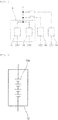
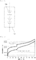
- FIG. 1 is a schematic circuit diagram of a vehicle according to the present embodiment.
- the vehicle 2 shown in FIG. 1 includes a power storage system 1.
- the power storage system 1 is used in a preferred manner, for example, for a power supply of a vehicle such as an automobile, a golf cart, a forklift, a rail vehicle, or an airplane, a transfer means such as a ship, or a transport means.
- the power storage system 1 is also used in a preferred manner as a power supply for an idling stop mechanism of an automobile that has the idling stop mechanism.
- the power storage system 1 is preferred for, in particular, electric vehicles such as a golf cart, a forklift, an electric wheelchair, a walker for an aged person, an electric scooter, an electric bicycle, an electric cart, an electric car, a Low Speed Vehicle (LSV), and an automated guided vehicle (AGV), which include a lead storage battery as a main power supply, and automobiles that have an idling stop function.
- electric vehicles such as a golf cart, a forklift, an electric wheelchair, a walker for an aged person, an electric scooter, an electric bicycle, an electric cart, an electric car, a Low Speed Vehicle (LSV), and an automated guided vehicle (AGV), which include a lead storage battery as a main power supply, and automobiles that have an idling stop function.
- LSV Low Speed Vehicle
- AGV automated guided vehicle
- the power storage system 1 is also preferred in power storage applications for power generators such as wind power generators, solar power generators, fuel cells, diesel generators, gasoline generators, and gas power generators.
- power generators such as wind power generators, solar power generators, fuel cells, diesel generators, gasoline generators, and gas power generators.
- the power storage system 1 includes a second power storage pack 11 and a first power storage pack 12.
- the second power storage pack 11 is a lead storage battery pack.
- the second power storage pack 11 is a power storage pack with 6 ⁇ n (n is a natural number of 1 or more and 125 or less) lead storage batteries connected in series will be described below in the present embodiment.
- the voltage range in normal use of the second power storage pack 11 is approximately (12.5 ⁇ n) V or higher and (12.8 ⁇ n) V or lower.
- the discharge cutoff voltage of the second power storage pack 11 is approximately (9.0 ⁇ n) V.
- the charge cutoff voltage of the second power storage pack 11 is approximately (14.8 ⁇ n) V.
- the first power storage pack 12 is connected in parallel to the second power storage pack 11. Specifically, the second power storage pack 11 and the first power storage pack are connected in parallel without any DCDC converter interposed therebetween.
- the first power storage pack 12 can be composed of, for example, a power storage pack such as a lithium ion storage battery pack and a nickel-metal-hydride storage battery pack.
- the first power storage pack 12 can be also composed of a capacitor such as a lithium ion capacitor (LIC) or an electric double layer capacitor (EDLC).
- LIC lithium ion capacitor
- EDLC electric double layer capacitor
- the "power storage device” means a storage battery such as a lead storage battery, a lithium ion storage battery, and a nickel-metal-hydride storage battery, and a unit cell such as a capacitor.
- the "power storage pack” includes at least one power storage device.
- a pack composed of at least one storage battery is referred to as a "storage battery pack".
- the lithium ion storage battery pack means a storage battery pack composed of at least one lithium ion storage battery.
- the lead storage battery pack means a storage battery pack composed of at least one lead storage battery.
- the nickel-metal-hydride storage battery pack means a storage battery pack composed of at least one nickel-metal-hydride storage battery.
- the power storage pack may be composed of one power storage module.
- the power storage pack may be composed of a plurality of power storage modules connected in parallel.
- the power storage pack may have a power storage module connected in parallel to at least one of a plurality of power storage modules connected in series.
- the "power storage module” means at least one power storage device connected in series. Accordingly, the power storage pack can have a power storage module.
- the plurality of power storage devices may have the same type of devices, or include multiple types of power storage devices.
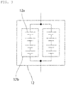
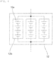
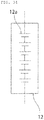
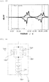
- first power storage pack 12 As shown in FIG. 2 , an example of the first power storage pack 12 with a plurality of power storage devices 12a connected in series will be described in the present embodiment. Specifically, an example of the first power storage pack 12 composed of four lithium ion storage batteries 12a connected in series will be described in the present embodiment.
- the first power storage pack is not necessarily required to be composed of one power storage module.
- a plurality of power storage modules 12b may be connected in parallel in the first power storage pack 12.
- a power storage module may be connected in parallel to at least one of a plurality of power storage modules 12b connected in series in the first power storage pack 12.
- each of the first and second power storage packs 11, 12 may further have a control unit for controlling a battery constituting each of the packs 11, 12.
- examples of a positive electrode active material included in a positive electrode of the lithium ion storage battery include inorganic compounds such as a composite oxide of a transition metal and lithium, a transition metal oxide, and a transition metal sulfide, and organic compounds.
- Examples of a negative electrode active material included in a negative electrode of the lithium ion storage battery include inorganic compounds such as a composite oxide of a transition metal and lithium, a metal oxide, an alloy material, and a transition metal sulfide, carbon materials, organic compounds, and lithium metals.
- the examples include composite oxides of transition metals and lithium, such as LiMn 2 O 4 , Li 4 Ti 5 O 12 , Li 2 Ti 3 O 7 , LiMg 1/2 Ti 3/2 O 4 , LiCo 1/2 Ti 3/2 O 4 , LiZn 1/2 Ti 3/2 O 4 , LiFeTiO 4 , LiCrTiO 4 , Li 2 SrTi e O 14 , and Li 2 BaTi 6 O 14 ; metal oxides such as TiO 2 , WO 3 , MoO 2 , MnO 2 , V 2 O 5 , SiO 2 , SiO, and SnO 2 ; alloy materials of Si, Sn, or the like; transition metal sulfides such as FeS and TiS; carbon materials such as graphite, non-graphitizable carbon, and graphitizable carbon; and organic compounds such as quinone compounds, disulfide compounds, diazine compounds, radialene compounds, rubeanic acid compounds, and organic radical compounds.
- the above-mentioned compounds with transition metal elements substituted with different types of elements may be used for the inorganic compounds.
- One of these negative electrode active materials may be used alone, or two or more thereof may be used concurrently.
- the above-mentioned negative electrode active materials subjected to pre-doping treatment with lithium ions may be used for the negative electrode active material.
- an electric load 13 composed of a motor or the like and a recharger 14 are connected in parallel to the power storage system 1. Between the power storage system 1 and each of the electric load 13 and the recharger 14, a switch is provided.
- a fuse or an FET switch may be provided between the second power storage pack 11 and the first power storage pack 12, if necessary.
- the electric power supplied from the recharger 14 is supplied to the second power storage pack 11 and the first power storage pack 12.
- electric power is supplied from the second power storage pack 11 and the first power storage pack 12 to the electric load 13.
- the second power storage pack 11 and the first power storage pack 12 are provided with a control device, if necessary, to be controlled such that no abnormality occurs, such as an overcharge/overdischarge state or overheat.
- the electric load 13 is specifically an electric motor, and during deceleration of the vehicle 2, decelerating regeneration is carried out in which regenerative energy is converted to electrical energy by the electric motor as the electric load 13 to charge the second power storage pack 11 and the first power storage pack 12.
- the power storage system 1 satisfies the following conditions (a), (b), and (c).
- the power storage system 1 satisfies the following conditions (d) and (e).
- the step of a charge/discharge curve refers to a range in which the voltage varies significantly in the range of 5% to 95% in the SOC of the first power storage pack 12, and specifically, refers to a range in which the absolute value of ⁇ V/ ⁇ SOC that is the proportion of the amount of change in voltage ( ⁇ V) on at least one of the charge curve or the discharge curve to the amount of change in SOC ( ⁇ SOC) is (100 ⁇ n) mV/% or more in the range of 5% to 95% in the SOC.
- the start point of a step means the minimum voltage of a discharge curve in the range of one step, and the SOC at the voltage.
- the end point of the step means the maximum voltage of a charge curve in the range of the same step, and the SOC at the voltage.
- the charge/discharge curve for the first power storage pack 12 refers to a charge/discharge curve in the case of constant-current charging/discharging in the voltage range from a discharge cutoff voltage to a charge cutoff voltage at a current value of 0.2 C under the condition of 25°C ⁇ 5°C.
- the "current value of 1 C” refers to a current value for charging or discharging to a rating capacity for 1 hour.
- the dQ/dV curve for the first power storage pack 12 refers to a curve (dQ/dV curve) obtained by differentiating the charge/discharge curve for the first power storage pack 12 with respect to voltage.
- the first power storage pack 12 according to the present embodiment satisfies all of the conditions (a), (b), (c), (d), and (e), but there is no need to limit the present invention thereto.
- the first power storage pack according to the present invention may satisfy only the conditions (a), (b), and (c).
- the first power storage pack according to the present invention may satisfy only the conditions (a), (d), and (e).
- the power storage system 1 satisfies the condition (a). For this reason, when the voltage of the second power storage pack 11 falls within the voltage range in normal use, the voltage of the first power storage pack 12 substantially coincides with the voltage of the second power storage pack 11 at the step of the charge/discharge curve for the first power storage pack 12, and the generation of a large voltage difference is eliminated between the first power storage pack 12 and the second power storage pack 11. Therefore, there is not always a need to provide a DCDC converter between the first power storage pack 12 and the second power storage pack 11. Accordingly, it becomes possible to reduce the price of the power storage system 1 and reduce the size thereof.
- the power storage system 1 satisfies at least one of the condition (b) and the condition (d). For this reason, when the first power storage pack 12 is required for large current output, the output from the first power storage pack 12 is also provided in a condition in which the voltage of the second power storage pack 11 is lower than the voltage range in normal use. Therefore, the voltage of the second power storage pack 11 can be prevented from being lower than the discharge cutoff voltage. Consequently, deterioration due to an overdischarge state of the second power storage pack 11 can be prevented, thereby allowing an increase in the life-span of the power storage system 1. In addition, there is not always a need for a special circuit for preventing an overdischarge state of the second power storage pack 11, thus allowing a reduction in the price of the power storage system 1.
- the power storage system 1 satisfies at least one of the condition (c) and the condition (e). For this reason, when the power storage system 1 is required for large current input, the input to the first power storage pack 12 is also provided in a condition in which the voltage of the second power storage pack 11 is higher than the voltage range in normal use. Consequently, the voltage of the second power storage pack 11 can be prevented from being higher than the charge cutoff voltage. Therefore, deterioration due to an overcharge state of the second power storage pack 11 can be prevented, thereby allowing an increase in the life-span of the power storage system 1. In addition, there is no need for a special circuit for preventing an overcharge state of the second power storage pack 11, thus allowing a reduction in the price of the power storage system 1.
- the negative electrode active material that causes a charge/discharge curve for the lithium ion storage battery to have a step include, for example, LiMn 2 O 4 , Li 4 Ti 5 O 12 , LiMg 1/2 Ti 3/2 O 4 , LiCo 1/2 Ti 3/2 O 4 , LiZn 1/2 Ti 3/2 O 4 , LiFeTiO 4 , LiCrTiO 4 , Li 2 SrTi 6 O 14 , Li 2 BaTi 6 O 14 , TiO 2 , WO 3 , MoO 2 , and MnO 2 . Only one of these negative electrode active materials may be used, or two or more thereof may be used in mixture.
- the positive electrode of the lithium ion storage battery is adapted to include the positive electrode active materials below.
- the negative electrode of the lithium ion storage battery is adapted to include the negative electrode active materials below.
- a method of configuring the first power storage pack 12 to have multiple types of power storage modules including different types of power storage devices is described.
- the first power storage pack 12 is adapted to include lithium ion storage batteries that differ in positive electrode active material, as with the following 1) to 8).
- the first power storage pack 12 is adapted to include lithium ion storage batteries that differ in negative electrode active material, as with the following 9) to 22).
- the first power storage pack 12 may be adapted to include at least two types of power storage modules selected from the group consisting of a lithium ion storage battery module, a nickel-metal-hydride storage battery module, a lead storage battery module, and a capacitor.
- turning on/off the switch forms a step in a charge/discharge curve.
- the power storage module which is relatively low in voltage is preferably provided with the switch.
- the switch turning off the switch before the power storage module provided with the switch is overcharged can form a step in a charge/discharge curve.
- the ratio preferably falls within the range of 10 : 90 to 90 : 10 between the capacity on the lower SOC side than the start point of the step of the charge/discharge curve for the first power storage pack 12 and the capacity on the higher SOC side than the end point of the step of the charge/discharge curve for the first power storage pack 12.
- the first power storage pack 12 can effectively prevent deterioration due to both an overcharge state and an overdischarge state of the second power storage pack 11, thereby allowing a further increase in the life-span of the power storage system 1.
- the second power storage pack 11 is preferably higher in capacity than the first power storage pack 12.
- the ratio between the capacity of the second power storage pack 11 and the capacity of the first power storage pack 12 preferably falls within the range of 55 : 45 to 99 : 1.
- the inexpensive lead storage battery pack accounts for most of the capacity of the power storage system 1, thus allowing a further reduction in the price of the power storage system 1.
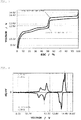
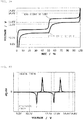
- Three of the lithium ion storage batteries 12a were connected in series as shown in FIG. 6 , thereby fabricating a first power storage pack 12, and a charge/discharge curve was measured.
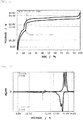
- FIG. 7 shows therein a charge/discharge curve for the first power storage pack 12 fabricated according to Example 1.
- FIG. 8 shows therein a curve (dQ/dV curve) obtained by differentiating the charge/discharge curve for the first power storage pack 12 fabricated according to Example 1 with respect to voltage.
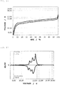
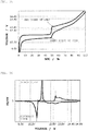
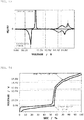
- Example 2 In the same way as in Example 1, except for the use of Li[Ni 0.05 Mn 1.95 ]O 4 as a positive electrode active material, a first power storage pack 12 was fabricated, and a charge/discharge curve was measured.
- FIG. 9 shows therein a charge/discharge curve for the first power storage pack 12, and
- FIG. 10 shows therein a dQ/dV curve therefor.
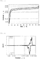
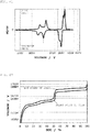
- Example 2 In the same way as in Example 1, except for the use of Li[Ni 0.15 Mn 1.85 ]O 4 as a positive electrode active material, a first power storage pack 12 was fabricated, and a charge/discharge curve was measured.
- FIG. 11 shows therein a charge/discharge curve for the first power storage pack 12, and
- FIG. 12 shows therein a dQ/dV curve therefor.
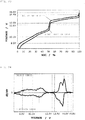
- Example 2 In the same way as in Example 1, except for the use of Li[Ni 0.35 Mn 1.65 ]O 4 as a positive electrode active material, a first power storage pack 12 was fabricated, and a charge/discharge curve was measured.
- FIG. 13 shows therein a charge/discharge curve for the first power storage pack 12, and
- FIG. 14 shows therein a dQ/dV curve therefor.
- Example 2 In the same way as in Example 1, except for the use of Li[Ni 0.45 Mn 1.55 ]O 4 as a positive electrode active material, a first power storage pack 12 was fabricated, and a charge/discharge curve was measured.
- FIG. 15 shows therein a charge/discharge curve for the first power storage pack 12, and
- FIG. 16 shows therein a dQ/dV curve therefor.
- a first power storage pack 12 was fabricated, and a charge/discharge curve was measured.
- FIG. 17 shows therein a charge/discharge curve for the first power storage pack 12, and
- FIG. 18 shows therein a dQ/dV curve therefor.
- Example 2 In the same way as in Example 1, except for the use of Li[Ni 0.50 Mn 1.50 ]O 4 as a positive electrode active material, a first power storage pack 12 was fabricated, and a charge/discharge curve was measured.
- FIG. 19 shows therein a charge/discharge curve for the first power storage pack 12, and
- FIG. 20 shows therein a dQ/dV curve therefor.
- Example 2 In the same way as in Example 1, except for the use of Li[Ni 0.25 Mn 1.75 ]O 4 as a positive electrode active material and the use of hard carbon as a negative electrode active material, a first power storage pack 12 was fabricated, and a charge/discharge curve was measured.
- FIG. 21 shows therein a charge/discharge curve for the first power storage pack 12, and
- FIG. 22 shows therein a dQ/dV curve therefor.
- Example 6 In the same way as in Example 6, except for the use of soft carbon as a negative electrode active material, a first power storage pack 12 was fabricated, and a charge/discharge curve was measured.
- FIG. 23 shows therein a charge/discharge curve for the first power storage pack 12, and
- FIG. 24 shows therein a dQ/dV curve therefor.
- FIG. 25 shows therein a charge/discharge curve for the first power storage pack 12, and
- FIG. 26 shows therein a dQ/dV curve therefor.
- FIG. 27 shows therein a charge/discharge curve for the first power storage pack 12, and
- FIG. 28 shows therein a dQ/dV curve therefor.
- Tables 1 and 2 show various types of data on Examples 1 to 9.
- the positions of the start point of the step and of the end point of the step can be easily adjusted by adjusting the value of x in the active material composition and the synthesis condition, and the ratio between the capacity on the lower SOC side than the start point of the step and the capacity on the higher SOC side than the end point of the step can be thus easily adjusted.
- the positions of the start point of the step and of the end point of the step can be adjusted by not only the value of x and the synthesis condition, but also the addition of different types of elements (for example, Li, Ti, Al, Mg, B, Cr, Co) or the substitution of the different types of elements for Ni or Mn.
- different types of elements for example, Li, Ti, Al, Mg, B, Cr, Co
- Three of the lithium ion storage battery devices 12a were connected in series as shown in FIG 6 , thereby fabricating a first power storage pack 12, and a charge/discharge curve was measured.
- FIG. 29 shows therein a charge/discharge curve for the first power storage pack 12
- FIG. 30 shows therein a dQ/dV curve therefor.
- Four of the lithium ion storage batteries 12a were connected in series as shown in FIG 33 , thereby fabricating a first power storage pack 12, and a charge/discharge curve was measured.
- FIG. 32 shows therein a charge/discharge curve for the first power storage pack 12
- FIG. 33 shows therein a dQ/dV curve therefor.
- Six of the lithium ion storage battery devices 12a were connected in series as shown in FIG 34 , thereby fabricating a first power storage pack 12, and a charge/discharge curve was measured.
- FIG. 35 shows therein a charge/discharge curve for the first power storage pack 12
- FIG. 36 shows therein a dQ/dV curve therefor.
- Tables 1 and 2 show various types of data on Examples 10 to 12.
- a lithium ion power storage module 12b1 with three of the lithium ion storage batteries 12a1 connected in series and a lithium ion power storage module 12b2 with three of the lithium ion storage batteries 12a2 connected in series were connected in parallel, thereby fabricating a first power storage pack 12, and a charge/discharge curve was measured.
- the measured charge/discharge curve was similar to the charge/discharge curve ( FIGS. 29, 30 ) according to Example 10.
- a lithium ion power storage module 12b1 composed of six of the lithium ion storage batteries 12a connected in series and a lithium ion power storage module 12b2 composed of seven of the lithium ion storage batteries 12a connected in series were connected in parallel, thereby fabricating a first power storage pack 12, and a charge/discharge curve was measured.
- FIG. 39 shows therein a charge/discharge curve for the first power storage pack 12
- FIG. 40 shows therein a dQ/dV curve therefor.
- Example 14 it is determined that the parallel connection of multiple power storage modules that differ in number of series connections makes it possible to design the first power storage pack 12 that satisfies at least one of the conditions (a), (b), and (c) and conditions (a), (d), and (e) mentioned above, in the case of using a lead storage battery pack as the second power storage pack 11.
- the capacity ratio between the two power storage modules is changed, the positions of the start point of the step and of the end point of the step can be adjusted, and the ratio between the capacity on the lower SOC side than the start point of the step and the capacity on the higher SOC side than the end point of the step can be thus also adjusted.
- FIG. 42 shows therein a charge/discharge curve for the first power storage pack 12
- FIG. 43 shows therein a dQ/dV curve therefor.
- Example 15 From the result presented in Example 15, it is determined that the parallel connection of multiple power storage modules that use different types of lithium ion storage batteries makes it possible to design the first power storage pack 12 that satisfies at least one of the conditions (a), (b), and (c) and conditions (a), (d), and (e) mentioned above, in the case of using a lead storage battery pack as the second power storage pack 11.
- changing the capacity ratio between the two power storage modules can adjust the positions of the start point of the step and of the end point of the step, and thus also adjust the ratio between the capacity on the lower SOC side than the start point of the step and the capacity on the higher SOC side than the end point of the step.
- a first power storage pack 12 was fabricated by connecting in series a lithium ion power storage module 12b1 composed of series-connected five of the lithium ion storage batteries 12a1 and a lithium ion power storage module 12b2 composed of one of the lithium ion storage batteries 12a2, and furthermore, connecting a lithium ion power storage module 12b3 composed of series-connected two of the lithium ion storage batteries 12a2 in parallel to the lithium ion power storage module 12b2, and a charge/discharge curve was measured.
- the measured charge/discharge curve was similar to the charge/discharge curve ( FIGS. 39, 40 ) according to Example 14.
- a first power storage pack 12 was fabricated by connecting in series a lithium ion power storage module 12b1 composed of series-connected two of the lithium ion storage batteries 12a1 and a lithium ion power storage module 12b2 composed of series-connected two of the lithium ion storage batteries 12a2, and furthermore, connecting series-connected three lithium ion power storage modules 12b3 in parallel to the lithium ion power storage module 12b2, and a charge/discharge curve was measured.
- the measured charge/discharge curve was similar to the charge/discharge curve ( FIGS. 44 , 45 ) according to Example 15.
- Three of the lithium ion storage batteries 12a were connected in series as shown in FIG. 6 as in Example 1, thereby fabricating a first power storage pack 12, and a charge/discharge curve was measured.
- FIG. 46 shows therein a charge/discharge curve for the first power storage pack 12, and
- FIG. 47 shows therein a dQ/dV curve therefor.
- the lithium ion storage batteries 12a were connected in series as shown in FIG. 6 as in Example 1, thereby fabricating a first power storage pack 12, and a charge/discharge curve was measured.
- FIG. 48 shows therein a charge/discharge curve for the first power storage pack 12, and
- FIG. 49 shows therein a dQ/dV curve therefor.
- Four of the lithium ion storage batteries 12a were connected in series as shown in FIG. 31 , thereby fabricating a first power storage pack 12, and a charge/discharge curve was measured.
- FIG. 50 shows therein a charge/discharge curve for the first power storage pack 12, and
- FIG. 51 shows therein a dQ/dV curve therefor.
- Six of the lithium ion storage batteries 12a were connected in series as shown in FIG. 34 , thereby fabricating a first power storage pack 12, and a charge/discharge curve was measured.
- FIG. 52 shows therein a charge/discharge curve for the first power storage pack 12
- FIG. 53 shows therein a dQ/dV curve therefor.
- FIG. 54 shows therein a charge/discharge curve for the first power storage pack 12
- FIG. 55 shows therein a dQ/dV curve therefor.
- the lithium ion storage batteries 12a were prepared.
- Six of the lithium ion storage batteries 12a were connected in series as shown in FIG. 34 , thereby fabricating a first power storage pack 12, and a charge/discharge curve was measured.
- FIG. 56 shows therein a charge/discharge curve for the first power storage pack 12
- FIG. 57 shows therein a dQ/dV curve therefor.
- FIG. 58 shows therein a charge/discharge curve for the first power storage pack 12
- FIG. 59 shows therein a dQ/dV curve therefor.
- Ninety of the lithium ion storage batteries 12a were connected in series, thereby fabricating a first power storage pack 12, and a charge/discharge curve was measured.
- FIG. 60 shows therein a charge/discharge curve for the first power storage pack 12, and
- FIG. 61 shows therein a dQ/dV curve therefor.
- FIG. 62 shows therein a charge/discharge curve for the first power storage pack 12
- FIG. 63 shows therein a dQ/dV curve therefor.
Landscapes
- Chemical & Material Sciences (AREA)
- Chemical Kinetics & Catalysis (AREA)
- Electrochemistry (AREA)
- General Chemical & Material Sciences (AREA)
- Engineering & Computer Science (AREA)
- Inorganic Chemistry (AREA)
- Manufacturing & Machinery (AREA)
- Materials Engineering (AREA)
- Composite Materials (AREA)
- Crystallography & Structural Chemistry (AREA)
- Power Engineering (AREA)
- Secondary Cells (AREA)
- Battery Mounting, Suspending (AREA)
- Battery Electrode And Active Subsutance (AREA)
- Connection Of Batteries Or Terminals (AREA)
Description
- The present invention relates to a power storage pack.
- Lead storage batteries are widely used in various applications, such as in-car applications for driving automobiles or for use as power supply to various types of electric loads, industrial applications for use as backup power supplies for commercial power supplies, and electric vehicle applications for use as main power supplies for golf carts, forklifts, and the like. Lead storage batteries are commonly used, such as six batteries connected in series for 12 V, and batteries configured for 24 V, 36 V, 48 V, 60 V, 72 V, and the like as multiples of 12 V.
- Lead storage batteries are low in price as compared with storage batteries such as lithium ion storage batteries and nickel-metal-hydride storage batteries, but inferior in charge/discharge cycle characteristics as compared with the storage batteries. In particular, lead storage batteries have charge/discharge cycle characteristics degraded significantly on reaching an overcharge state or an overdischarge state. For example, when a lead storage battery reaches an overcharge state, gas generation and a decrease in amount of electrolytic solution, corrosion of a current collector, and loss of an active material due to electrolysis of sulfuric acid as an electrolytic solution will be caused, thereby degrading charge/discharge cycle characteristics. Alternatively, when a lead storage battery reaches an overdischarge state, positive and negative electrode surfaces covered with a lead sulfate which is a reaction product and an insulator will inhibit smooth charge/discharge reactions, thus degrading charge/discharge cycle characteristics.
- Therefore, in particular, when only a lead storage battery is used as a storage battery for an in-car application or an electric vehicle, there is concern about early deterioration of the lead storage battery. When this concern is addressed by simply replacing the lead storage battery with a storage battery which is superior in charge/discharge cycle characteristics to lead storage batteries such as lithium ion storage batteries and nickel-metal-hydride storage batteries, an increase in the price of the storage battery will be caused.
- Therefore, Japanese Patent Application
2007-131134 - In the above regard, not only the lead storage batteries described previously, but also power storage devices commonly undergo early deterioration on reaching an overcharge state or an overdischarge state. Therefore, it is desirable to use the power storage devices to the extent that an SOC (State of Charge: the proportion of a charging capacity to the amount of charge in a full charge state) that represents a state of charging a storage battery reaches no overcharge/overdischarge state (SOC range of use).
- When the lead storage battery and the high-performance storage battery such as a lithium ion storage battery differ in open-circuit voltage, directly connecting both of power storage batteries in parallel leads to concern about electric current flowing into the storage battery on the lower open-circuit voltage side from the storage battery on the higher open-circuit voltage side, or on the other hand, reaching an overcharge/overdischarge state with both of the storage batteries outside the SOC range of use.
- Therefore, in the power storage system described in
JP2007-131134 - However, the DC-DC converter is high in price and large in size, and the power storage system described in
JP2007-131134 - We have appreciated that it would be desirable to achieve an increase in the life-span of a power storage system, a reduction in the price thereof, and a reduction in the size thereof.
-
US 2011/086248 discloses an assembled battery including a combination of two kinds of secondary batteries differing in battery property (charge voltage behavior), each secondary battery including a positive electrode, a negative electrode, a separator interposed between the positive and negative electrodes, and a non-aqueous electrolyte.US 2011/086248 relates to an assembled battery including at least one first cell and at least one second cell electrically connected in series. The second cell has a greater change in charge voltage at the end of charge and a larger cell capacity. -
EP3223336 discloses an on-vehicle battery including a lead storage battery and a second storage battery. The second storage battery is connected in parallel with the lead storage battery. The second storage battery has a positive electrode and a negative electrode. The positive electrode includes, as a positive electrode active material, a spinel-type lithium-nickel-manganese oxide. The negative electrode includes, as a negative electrode active material, at least one of graphite, soft carbon, hard carbon, and an alloy-based material containing an Si element. - The invention is defined in the independent claims to which reference should now be made. Advantageous features are set forth in the dependent claims.
- A first power storage pack according to the present invention is for connection in parallel with a second power storage pack with a different battery chemistry and without any DC-DC converter interposed between the first power storage pack and the second power storage pack. A charge/discharge curve of the first power storage pack measured with a constant C-rate has a step passing through a range of (12.5 × n) V or higher and (12.8 × n) V or lower, where n is a natural number of 1 or more and 125 or less. On a lower state of charge, SOC, side than a start point of the step of the charge/discharge curve of the first power storage pack, an average discharge voltage falls within a range of (9.0 × n) V or higher and (12.5 × n) V or lower and/or a voltage at a peak top obtained on a dQ/dV curve obtained by differentiating the discharge curve with respect to voltage falls within a range of (9.0 × n) V or higher and (12.5 × n) V or lower. On a higher SOC side than an end point of the step of the charge/discharge curve of the first power storage pack, an average charge voltage falls within the range of (12.8 × n) V or higher and (14.8 × n) V or lower and/or a voltage at a peak top obtained on a dQ/dV curve obtained by differentiating the charge curve with respect to voltage falls within the range of (12.8 × n) V or higher and (14.8 × n) V or lower. A step of a charge or discharge curve refers to a range in which the proportion of the amount of change in voltage, ΔV, on the charge/discharge curve to the amount of change in SOC, ΔSOC, is (100 × n) mV/% or more, when the SOC is in the range of 5% to 95%. The start point of a step is the minimum voltage of a discharge curve in the range of one step, and the corresponding value of the SOC at the minimum voltage, and the end point of the step is the maximum voltage of a charge curve in the range of the same step, and the corresponding value of the SOC at the maximum voltage.
- It is possible to use, as a power storage system, the first power storage pack according to the present invention, connected in parallel to a second power storage pack with 6 × n lead storage batteries connected in series. The second power storage pack with the 6 × n lead storage batteries connected in series represents a lead storage battery pack configured for a multiple of 12 V. In the case of n = 1, the second power storage pack with the 6 × n lead storage batteries connected in series represents a lead storage battery pack configured for 12 V with six lead storage batteries connected in series. In the case of n = 2, the second power storage pack with the 6 × n lead storage batteries connected in series represents a lead storage battery pack configured for 24 V with twelve lead storage batteries connected in series, or a lead storage battery pack configured for 24 V with two series-connected lead storage batteries each configured for 12 V. The same applies to cases with n of 3 or more.
- The first power storage pack according to the present invention has a step passing through the range of (12.5 × n) V or higher and (12.8 × n) V or lower (n is a natural number of 1 or more and 125 or less). For this reason, for example, in a power storage system in which a second power storage pack with 6 × n lead storage batteries connected in series is connected in parallel to the first power storage pack according to the present invention, when the voltage of the lead storage battery pack falls within the voltage range in normal use, the voltage of the first power storage pack according to the present invention substantially coincides with the voltage of the lead storage battery pack at the step of the charge/discharge curve for the first power storage pack according to the present invention. The generation of a large voltage difference is eliminated between the power storage pack according to the present invention and the lead storage battery pack. Therefore, there is not always a need to provide a DC-DC converter between the first power storage pack according to the present invention and the lead storage battery pack. Accordingly, for example, the use of the first power storage pack according to the present invention makes it possible to reduce the price of a power storage system including the lead storage battery pack, and reduce the size thereof.
- The average discharge voltage on the lower SOC side than the start point of the step of the charge/discharge curve for the first power storage pack according to the present invention falls within the range of (9.0 × n) V or higher and (12.5 × n) V or lower. For this reason, when the power storage system with the parallel-connected power storage packs each with the 6 × n lead storage batteries connected in series is required for large current output, the output from the power storage packs according to the present invention is also provided in a condition in which the voltage of the lead storage battery pack is lower than the voltage range in normal use, thereby making it possible to prevent the voltage of the lead storage battery pack from being lower than the discharge cutoff voltage. Therefore, deterioration due to an overdischarge state of the lead storage battery pack can be prevented, thereby allowing an increase in the life-span of the power storage system. In addition, there is no need for a special circuit for preventing an overdischarge state of the lead storage battery pack, thus allowing a reduction in the price of the power storage system.
- The average charge voltage on the higher SOC side than the end point of the step of the charge/discharge curve for the first power storage pack according to the present invention falls within the range of (12.8 × n) V or higher and (14.8 × n) V or lower. For this reason, when the power storage system with the parallel-connected power storage packs each with the 6 × n lead storage batteries connected in series is required for large current input, the input to the power storage packs according to the present invention is also provided in a condition in which the voltage of the lead storage battery pack is higher than the voltage range in normal use, thereby making it possible to prevent the voltage of the lead storage battery pack from being higher than the charge cutoff voltage. Therefore, deterioration due to an overcharge state of the lead storage battery pack can be prevented, thereby allowing an increase in the life-span of the power storage system. In addition, there is no need for a special circuit for preventing an overcharge state of the lead storage battery pack, thus allowing a reduction in the price of the power storage system.
- The charge/discharge curve for a first power storage pack according to the present invention has a step passing through the range of (12.5 × n) V or higher and (12.8 × n) V or lower (n is a natural number of 1 or more and 125 or less). On the lower SOC side than the start point of the step of the charge/discharge curve for the first power storage pack according to the present invention, the voltage at the peak top obtained on the curve (dQ/dV curve) obtained by differentiating, with respect to voltage, the discharge curve for the first power storage pack falls within the range of (9.0 × n) V or higher and (12.5 × n) V or lower. On the higher SOC side than the end point of the step of the charge/discharge curve for the first power storage pack according to the present invention, the voltage at the peak top obtained on the curve (dQ/dV curve) obtained by differentiating, with respect to voltage, the charge curve for the first power storage pack falls within the range of (12.8 × n) V or higher and (14.8 × n) V or lower.
- It is possible to use, as a power storage system, the first power storage pack according to the present invention, connected in parallel to a second power storage pack with 6 × n lead storage batteries connected in series.
- The first power storage pack according to the present invention has a step passing through the range of (12.5 × n) V or higher and (12.8 × n) V or lower (n is a natural number of 1 or more and 125 or less). For this reason, for example, in a power storage system in which a second power storage pack with 6 × n lead storage batteries connected in series is connected in parallel to the first power storage pack according to the present invention, when the voltage of the lead storage battery pack falls within the voltage range in normal use, the voltage of the first power storage pack according to the present invention substantially coincides with the voltage of the lead storage battery pack at the step of the charge/discharge curve for the first power storage pack according to the present invention. The generation of a large voltage difference is eliminated between the first power storage pack according to the present invention and the lead storage battery pack. Therefore, there is not always a need to provide a DC-DC converter between the first power storage pack according to the present invention and the lead storage battery pack. Accordingly, for example, the use of the first power storage pack according to the present invention makes it possible to reduce the price of a power storage system including the lead storage battery pack, and reduce the size thereof.
- On the lower SOC side than the start point of the step of the charge/discharge curve for the first power storage pack according to the present invention, the voltage at the peak top obtained on the curve (dQ/dV curve) obtained by differentiating, with respect to voltage, the discharge curve for the first power storage pack falls within the range of (9.0 × n) V or higher and (12.5 × n) V or lower. For this reason, when the power storage system with the parallel-connected power storage packs each with the 6 × n lead storage batteries connected in series is required for large current output, the output from the power storage packs according to the present invention is also provided in a condition in which the voltage of the lead storage battery pack is lower than the voltage range in normal use, thereby making it possible to prevent the voltage of the lead storage battery pack from being lower than the discharge cutoff voltage. Therefore, deterioration due to an overdischarge state of the lead storage battery pack can be prevented, thereby allowing an increase in the life-span of the power storage system. In addition, there is no need for a special circuit for preventing an overdischarge state of the lead storage battery pack, thus allowing a reduction in the price of the power storage system.
- On the higher SOC side than the end point of the step of the charge/discharge curve for the first power storage pack according to the present invention, the voltage at the peak top obtained on the curve (dQ/dV curve) obtained by differentiating, with respect to voltage, the charge curve for the first power storage pack falls within the range of (12.8 × n) V or higher and (14.8 × n) V or lower. For this reason, when the power storage system with the parallel-connected power storage packs each with the 6 × n lead storage batteries connected in series is required for large current input, the input to the power storage packs according to the present invention is also provided in a condition in which the voltage of the lead storage battery pack is higher than the voltage range in normal use, thereby making it possible to prevent the voltage of the lead storage battery pack from being higher than the charge cutoff voltage. Therefore, deterioration due to an overcharge state of the lead storage battery pack can be prevented, thereby allowing an increase in the life-span of the power storage system. In addition, there is no need for a special circuit for preventing an overcharge state of the lead storage battery pack, thus allowing a reduction in the price of the power storage system.
- The first power storage pack according to the present invention may include a power storage device, and the power storage device may be a lithium ion storage battery or a nickel-metal-hydride storage battery.
- The first power storage pack according to the present invention may include a lithium ion storage battery, and the lithium ion storage battery may have a positive electrode including at least one selected from the group consisting of Li[NixMn(2-x)]O4 (0.05 ≤ x ≤ 0.45), Li[CoxMn(2-x)]O4 (0.1 ≤ x ≤ 1), Li[FexMn(2-x)]O4 (0.05 ≤ x ≤ 0.45), LiFeaMnbCocNidPO4 (0 ≤ a ≤ 1, 0 ≤ b ≤ 1, 0 ≤ c ≤ 1, 0 ≤ d ≤ 1, a + b + c + d = 1), and Li3V2(PO4)3 as a positive electrode active material.
- The first power storage pack according to the present invention may include a lithium ion storage battery, and the lithium ion storage battery may have a positive electrode including multiple kinds of positive electrode active materials.
- The first power storage pack according to the present invention may include a lithium ion storage battery, and the lithium ion storage battery may have a negative electrode including multiple kinds of negative electrode active materials.
- The first power storage pack according to the present invention may be composed of a plurality of power storage modules connected in parallel, which is composed of a plurality of power storage devices connected in series, and the plurality of power storage modules may include power storage modules that differ from each other in number of connection stages. The first power storage pack according to the present invention may include multiple types of power storage modules that have different types of power storage devices.
- The ratio preferably falls within the range of 10 : 90 to 90 : 10 between the capacity on the lower SOC side than the start point of a step of the charge/discharge curve for the first power storage pack according to the present invention and the capacity on the higher SOC side than the end point of the step of the charge/discharge curve for the first power storage pack.
- According to the present invention, an increase in the life-span of a power storage system, a reduction in the price thereof, and a reduction in the size thereof can be achieved.
-
-
FIG. 1 is a schematic circuit diagram of a vehicle according to an embodiment of the present invention. -
FIG. 2 is a schematic circuit diagram of a first power storage pack according to an embodiment of the present invention. -
FIG. 3 is a schematic circuit diagram of a first power storage pack according to a first modification example. -
FIG. 4 is a schematic circuit diagram of a first power storage pack according to a second modification example. -
FIG. 5 is a schematic circuit diagram of a first power storage pack according to a third modification example. -
FIG. 6 is a schematic circuit diagram of a firstpower storage pack 12 fabricated according to Example 1. -
FIG. 7 is a charge/discharge curve for the firstpower storage pack 12 fabricated according to Example 1. -
FIG. 8 is a curve (dQ/dV curve) obtained by differentiating the charge/discharge curve for the firstpower storage pack 12 fabricated according to Example 1 with respect to voltage. -
FIG. 9 is a charge/discharge curve for a firstpower storage pack 12 fabricated according to Example 2. -
FIG. 10 is a curve (dQ/dV curve) obtained by differentiating the charge/discharge curve for the firstpower storage pack 12 fabricated according to Example 2 with respect to voltage. -
FIG. 11 is a charge/discharge curve for a firstpower storage pack 12 fabricated according to Example 3. -
FIG. 12 is a curve (dQ/dV curve) obtained by differentiating the charge/discharge curve for the firstpower storage pack 12 fabricated according to Example 3 with respect to voltage. -
FIG. 13 is a charge/discharge curve for a firstpower storage pack 12 fabricated according to Example 4. -
FIG. 14 is a curve (dQ/dV curve) obtained by differentiating the charge/discharge curve for the firstpower storage pack 12 fabricated according to Example 4 with respect to voltage. -
FIG. 15 is a charge/discharge curve for a firstpower storage pack 12 fabricated according to Example 5. -
FIG. 16 is a curve (dQ/dV curve) obtained by differentiating the charge/discharge curve for the firstpower storage pack 12 fabricated according to Example 5 with respect to voltage. -
FIG. 17 is charge/discharge curve for a firstpower storage pack 12 fabricated according to Reference Example 1. -
FIG. 18 is a curve (dQ/dV curve) obtained by differentiating the charge/discharge curve for the firstpower storage pack 12 fabricated according to Reference Example 1 with respect to voltage. -
FIG. 19 is charge/discharge curve for a firstpower storage pack 12 fabricated according to Reference Example 2. -
FIG. 20 is a curve (dQ/dV curve) obtained by differentiating the charge/discharge curve for the firstpower storage pack 12 fabricated according to Reference Example 2 with respect to voltage. -
FIG. 21 is a charge/discharge curve for a firstpower storage pack 12 fabricated according to Example 6. -
FIG. 22 is a curve (dQ/dV curve) obtained by differentiating the charge/discharge curve for the firstpower storage pack 12 fabricated according to Example 6 with respect to voltage. -
FIG. 23 is a charge/discharge curve for a firstpower storage pack 12 fabricated according to Example 7. -
FIG. 24 is a curve (dQ/dV curve) obtained by differentiating the charge/discharge curve for the firstpower storage pack 12 fabricated according to Example 7 with respect to voltage. -
FIG. 25 is a charge/discharge curve for a firstpower storage pack 12 fabricated according to Example 8. -
FIG. 26 is a curve (dQ/dV curve) obtained by differentiating the charge/discharge curve for the firstpower storage pack 12 fabricated according to Example 8 with respect to voltage. -
FIG. 27 is a charge/discharge curve for a firstpower storage pack 12 fabricated according to Example 9. -
FIG. 28 is a curve (dQ/dV curve) obtained by differentiating the charge/discharge curve for the firstpower storage pack 12 fabricated according to Example 9 with respect to voltage. -
FIG. 29 is a charge/discharge curve for a firstpower storage pack 12 fabricated according to Example 10. -
FIG. 30 is a curve (dQ/dV curve) obtained by differentiating the charge/discharge curve for the firstpower storage pack 12 fabricated according to Example 10 with respect to voltage. -
FIG. 31 is a schematic circuit diagram of a first power storage pack fabricated according to Example 11. -
FIG. 32 is a charge/discharge curve for the firstpower storage pack 12 fabricated according to Example 11. -
FIG. 33 is a curve (dQ/dV curve) obtained by differentiating the charge/discharge curve for the firstpower storage pack 12 fabricated according to Example 11 with respect to voltage. -
FIG. 34 is a schematic circuit diagram of a first power storage pack fabricated according to Example 12. -
FIG. 35 is a charge/discharge curve for the firstpower storage pack 12 fabricated according to Example 12. -
FIG. 36 is a curve (dQ/dV curve) obtained by differentiating the charge/discharge curve for the firstpower storage pack 12 fabricated according to Example 12 with respect to voltage. -
FIG. 37 is a schematic circuit diagram of a first power storage pack fabricated according to Example 13. -
FIG. 38 is a schematic circuit diagram of a first power storage pack fabricated according to Example 14. -
FIG. 39 is a charge/discharge curve for the firstpower storage pack 12 fabricated according to Example 14. -
FIG. 40 is a curve (dQ/dV curve) obtained by differentiating the charge/discharge curve for the firstpower storage pack 12 fabricated according to Example 14 with respect to voltage. -
FIG. 41 is a schematic circuit diagram of a first power storage pack fabricated according to Example 15. -
FIG. 42 is a charge/discharge curve for the firstpower storage pack 12 fabricated according to Example 15. -
FIG. 43 is a curve (dQ/dV curve) obtained by differentiating the charge/discharge curve for the firstpower storage pack 12 fabricated according to Example 15 with respect to voltage. -
FIG. 44 is a schematic circuit diagram of a first power storage pack fabricated according to Example 16. -
FIG. 45 is a schematic circuit diagram of a first power storage pack fabricated according to Example 17. -
FIG. 46 is charge/discharge curve for a firstpower storage pack 12 fabricated according to Reference Example 3. -
FIG. 47 is a curve (dQ/dV curve) obtained by differentiating the charge/discharge curve for the firstpower storage pack 12 fabricated according to Reference Example 3 with respect to voltage. -
FIG. 48 is charge/discharge curve for a firstpower storage pack 12 fabricated according to Reference Example 4. -
FIG. 49 is a curve (dQ/dV curve) obtained by differentiating the charge/discharge curve for the firstpower storage pack 12 fabricated according to Reference Example 4 with respect to voltage. -
FIG. 50 is charge/discharge curve for a firstpower storage pack 12 fabricated according to Reference Example 5. -
FIG. 51 is a curve (dQ/dV curve) obtained by differentiating the charge/discharge curve for the firstpower storage pack 12 fabricated according to Reference Example 5 with respect to voltage. -
FIG. 52 is charge/discharge curve for a firstpower storage pack 12 fabricated according to Reference Example 6. -
FIG. 53 is a curve (dQ/dV curve) obtained by differentiating the charge/discharge curve for the firstpower storage pack 12 fabricated according to Reference Example 6 with respect to voltage. -
FIG. 54 is charge/discharge curve for a firstpower storage pack 12 fabricated according to Reference Example 7. -
FIG. 55 is a curve (dQ/dV curve) obtained by differentiating the charge/discharge curve for the firstpower storage pack 12 fabricated according to Reference Example 7 with respect to voltage. -
FIG. 56 is a charge/discharge curve for a firstpower storage pack 12 fabricated according to Example 18. -
FIG. 57 is a curve (dQ/dV curve) obtained by differentiating the charge/discharge curve for the firstpower storage pack 12 fabricated according to Example 18 with respect to voltage. -
FIG. 58 is a charge/discharge curve for a firstpower storage pack 12 fabricated according to Example 19. -
FIG. 59 is a curve (dQ/dV curve) obtained by differentiating the charge/discharge curve for the firstpower storage pack 12 fabricated according to Example 19 with respect to voltage. -
FIG. 60 is a charge/discharge curve for a firstpower storage pack 12 fabricated according to Example 20. -
FIG. 61 is a curve (dQ/dV curve) obtained by differentiating the charge/discharge curve for the firstpower storage pack 12 fabricated according to Example 20 with respect to voltage. -
FIG. 62 is a charge/discharge curve for a firstpower storage pack 12 fabricated according to Example 21. -
FIG. 63 is a curve (dQ/dV curve) obtained by differentiating the charge/discharge curve for the firstpower storage pack 12 fabricated according to Example 21 with respect to voltage. - An example of a preferred embodiment of the present invention will be described below. However, the following embodiment is considered by way of example only. The present invention is not limited to the following embodiment in any way. In addition, members that have substantially the same functions shall be denoted by the same reference symbols in the respective drawings referred to in the embodiment and the like.
-
FIG. 1 is a schematic circuit diagram of a vehicle according to the present embodiment. - The
vehicle 2 shown inFIG. 1 includes apower storage system 1. An example of using thepower storage system 1 for thevehicle 2 will be described in the present embodiment, but the application of thepower storage system 1 is not limited thereto. Thepower storage system 1 is used in a preferred manner, for example, for a power supply of a vehicle such as an automobile, a golf cart, a forklift, a rail vehicle, or an airplane, a transfer means such as a ship, or a transport means. For example, thepower storage system 1 is also used in a preferred manner as a power supply for an idling stop mechanism of an automobile that has the idling stop mechanism. Thepower storage system 1 is preferred for, in particular, electric vehicles such as a golf cart, a forklift, an electric wheelchair, a walker for an aged person, an electric scooter, an electric bicycle, an electric cart, an electric car, a Low Speed Vehicle (LSV), and an automated guided vehicle (AGV), which include a lead storage battery as a main power supply, and automobiles that have an idling stop function. It is to be noted that whileFIG. 1 is a schematic conceptual diagram of a vehicle, the system inFIG. 1 is also used as well for a transfer mechanism and a transport mechanism. - In addition, the
power storage system 1 is also preferred in power storage applications for power generators such as wind power generators, solar power generators, fuel cells, diesel generators, gasoline generators, and gas power generators. - The
power storage system 1 includes a secondpower storage pack 11 and a firstpower storage pack 12. The secondpower storage pack 11 is a lead storage battery pack. - An example in which the second
power storage pack 11 is a power storage pack with 6 × n (n is a natural number of 1 or more and 125 or less) lead storage batteries connected in series will be described below in the present embodiment. In this case, the voltage range in normal use of the secondpower storage pack 11 is approximately (12.5 × n) V or higher and (12.8 × n) V or lower. The discharge cutoff voltage of the secondpower storage pack 11 is approximately (9.0 × n) V. The charge cutoff voltage of the secondpower storage pack 11 is approximately (14.8 × n) V. - The first
power storage pack 12 is connected in parallel to the secondpower storage pack 11. Specifically, the secondpower storage pack 11 and the first power storage pack are connected in parallel without any DCDC converter interposed therebetween. - The first
power storage pack 12 can be composed of, for example, a power storage pack such as a lithium ion storage battery pack and a nickel-metal-hydride storage battery pack. In addition, the firstpower storage pack 12 can be also composed of a capacitor such as a lithium ion capacitor (LIC) or an electric double layer capacitor (EDLC). - It is to be noted that in the present invention the "power storage device" means a storage battery such as a lead storage battery, a lithium ion storage battery, and a nickel-metal-hydride storage battery, and a unit cell such as a capacitor.
- In the present invention, the "power storage pack" includes at least one power storage device. Among power storage packs, a pack composed of at least one storage battery is referred to as a "storage battery pack". Accordingly, the lithium ion storage battery pack means a storage battery pack composed of at least one lithium ion storage battery. The lead storage battery pack means a storage battery pack composed of at least one lead storage battery. The nickel-metal-hydride storage battery pack means a storage battery pack composed of at least one nickel-metal-hydride storage battery.
- The power storage pack may be composed of one power storage module. The power storage pack may be composed of a plurality of power storage modules connected in parallel. The power storage pack may have a power storage module connected in parallel to at least one of a plurality of power storage modules connected in series.
- In the present invention, the "power storage module" means at least one power storage device connected in series. Accordingly, the power storage pack can have a power storage module.
- According to the present invention, when a power storage pack has a plurality of power storage devices, the plurality of power storage devices may have the same type of devices, or include multiple types of power storage devices.
- As shown in
FIG. 2 , an example of the firstpower storage pack 12 with a plurality ofpower storage devices 12a connected in series will be described in the present embodiment. Specifically, an example of the firstpower storage pack 12 composed of four lithiumion storage batteries 12a connected in series will be described in the present embodiment. - According to the present invention, the first power storage pack is not necessarily required to be composed of one power storage module. For example, as shown in
FIGS. 3 and4 , a plurality ofpower storage modules 12b may be connected in parallel in the firstpower storage pack 12. For example, as shown inFIG. 5 , a power storage module may be connected in parallel to at least one of a plurality ofpower storage modules 12b connected in series in the firstpower storage pack 12. - It is to be noted that each of the first and second power storage packs 11, 12 may further have a control unit for controlling a battery constituting each of the
packs - When the first
power storage pack 12 is a lithium ion storage battery pack, examples of a positive electrode active material included in a positive electrode of the lithium ion storage battery include inorganic compounds such as a composite oxide of a transition metal and lithium, a transition metal oxide, and a transition metal sulfide, and organic compounds. Specifically, the examples include composite oxides of transition metals and lithium, such as LiC0O2, LiNiO2, LiMnO2, LiMn2O4, Li(1+a)NixMnyCozO2 (0 ≤ a ≤ 0.5, 0 ≤ x ≤ 1, 0 ≤ y ≤ 1, 0 ≤ z ≤ 1, x + y + z = 1), Li[NixMn(2-x)]O4 (0 ≤ x ≤ 0.5), Li[CoxMn(2-x)]O4 (0 ≤ x ≤1), Li[FexMn(2-x)]O4 (0 ≤ x ≤ 1), LiNiVO4, LiFePO4, LiMnPO4, LiCOPO4, LiNiPO4, LiFeaMnbCocNidPO4 (0 ≤ a≤ 1, 0 ≤ b ≤ 1, 0 ≤ c ≤1, 0 ≤ d ≤1, a + b + c + d = 1), Li3V2(PO4)3, and LiVOPO4; transition metal oxides such as MnO2, MnO, and V2O5; transition metal sulfides such as FeS and TiS; and organic compounds such as quinone compounds, disulfide compounds, diazine compounds, radialene compounds, rubeanic acid compounds, and organic radical compounds. The above-mentioned compounds with transition metal elements substituted with different types of elements may be used for the inorganic compounds. One of these positive electrode active materials may be used alone, or two or more thereof may be used concurrently. - Examples of a negative electrode active material included in a negative electrode of the lithium ion storage battery include inorganic compounds such as a composite oxide of a transition metal and lithium, a metal oxide, an alloy material, and a transition metal sulfide, carbon materials, organic compounds, and lithium metals. Specifically, the examples include composite oxides of transition metals and lithium, such as LiMn2O4, Li4Ti5O12, Li2Ti3O7, LiMg1/2Ti3/2O4, LiCo1/2Ti3/2O4, LiZn1/2Ti3/2O4, LiFeTiO4, LiCrTiO4, Li2SrTieO14, and Li2BaTi6O14; metal oxides such as TiO2, WO3, MoO2, MnO2, V2O5, SiO2, SiO, and SnO2; alloy materials of Si, Sn, or the like; transition metal sulfides such as FeS and TiS; carbon materials such as graphite, non-graphitizable carbon, and graphitizable carbon; and organic compounds such as quinone compounds, disulfide compounds, diazine compounds, radialene compounds, rubeanic acid compounds, and organic radical compounds. The above-mentioned compounds with transition metal elements substituted with different types of elements may be used for the inorganic compounds. One of these negative electrode active materials may be used alone, or two or more thereof may be used concurrently. In addition, the above-mentioned negative electrode active materials subjected to pre-doping treatment with lithium ions may be used for the negative electrode active material.
- According to the present embodiment, an
electric load 13 composed of a motor or the like and arecharger 14 are connected in parallel to thepower storage system 1. Between thepower storage system 1 and each of theelectric load 13 and therecharger 14, a switch is provided. - Further, in order to enhance the safety of the
power storage system 1, a fuse or an FET switch may be provided between the secondpower storage pack 11 and the firstpower storage pack 12, if necessary. - The electric power supplied from the
recharger 14 is supplied to the secondpower storage pack 11 and the firstpower storage pack 12. When theelectric load 13 is operated without connecting therecharger 14, electric power is supplied from the secondpower storage pack 11 and the firstpower storage pack 12 to theelectric load 13. The secondpower storage pack 11 and the firstpower storage pack 12 are provided with a control device, if necessary, to be controlled such that no abnormality occurs, such as an overcharge/overdischarge state or overheat. - According to the present embodiment, the
electric load 13 is specifically an electric motor, and during deceleration of thevehicle 2, decelerating regeneration is carried out in which regenerative energy is converted to electrical energy by the electric motor as theelectric load 13 to charge the secondpower storage pack 11 and the firstpower storage pack 12. - The
power storage system 1 satisfies the following conditions (a), (b), and (c). - (a) The charge/discharge curve for the first
power storage pack 12 has a step passing through the range of (12.5 × n) V or higher and (12.8 × n) V or lower (n is a natural number of 1 or more and 125 or less). - (b) The average discharge voltage on the lower SOC side than the start point of the step of the charge/discharge curve for the first
power storage pack 12 falls within the range of (9.0 × n) V or higher and (12.5 × n) V or lower. - (c) The average charge voltage on the higher SOC side than the end point of the step of the charge/discharge curve for the first
power storage pack 12 falls within the range of (12.8 × n) V or higher and (14.8 × n) V or lower. - Furthermore, the
power storage system 1 satisfies the following conditions (d) and (e). - (d) On the lower SOC side than the start point of the step of the charge/discharge curve for the first
power storage pack 12, the voltage at the peak top obtained on the curve (dQ/dV curve) obtained by differentiating, with respect to voltage, the discharge curve for the first power storage pack falls within the range of (9.0 × n) V or higher and (12.5 × n) V or lower. - (e) On the higher SOC side than the end point of the step of the charge/discharge curve for the first
power storage pack 12, the voltage at the peak top obtained on the curve (dQ/dV curve) obtained by differentiating, with respect to voltage, the charge curve for the first power storage pack falls within the range of (12.8 × n) V or higher and (14.8 × n) V or lower. - In the present invention, "the step of a charge/discharge curve" refers to a range in which the voltage varies significantly in the range of 5% to 95% in the SOC of the first
power storage pack 12, and specifically, refers to a range in which the absolute value of ΔV/ΔSOC that is the proportion of the amount of change in voltage (ΔV) on at least one of the charge curve or the discharge curve to the amount of change in SOC (ΔSOC) is (100 × n) mV/% or more in the range of 5% to 95% in the SOC. - "The start point of a step" means the minimum voltage of a discharge curve in the range of one step, and the SOC at the voltage.
- "The end point of the step" means the maximum voltage of a charge curve in the range of the same step, and the SOC at the voltage.
- The charge/discharge curve for the first
power storage pack 12 refers to a charge/discharge curve in the case of constant-current charging/discharging in the voltage range from a discharge cutoff voltage to a charge cutoff voltage at a current value of 0.2 C under the condition of 25°C ± 5°C. The "current value of 1 C" refers to a current value for charging or discharging to a rating capacity for 1 hour. In addition, the dQ/dV curve for the firstpower storage pack 12 refers to a curve (dQ/dV curve) obtained by differentiating the charge/discharge curve for the firstpower storage pack 12 with respect to voltage. - It is to be noted that the first
power storage pack 12 according to the present embodiment satisfies all of the conditions (a), (b), (c), (d), and (e), but there is no need to limit the present invention thereto. The first power storage pack according to the present invention may satisfy only the conditions (a), (b), and (c). Alternatively, the first power storage pack according to the present invention may satisfy only the conditions (a), (d), and (e). - The
power storage system 1 according to the present embodiment satisfies the condition (a). For this reason, when the voltage of the secondpower storage pack 11 falls within the voltage range in normal use, the voltage of the firstpower storage pack 12 substantially coincides with the voltage of the secondpower storage pack 11 at the step of the charge/discharge curve for the firstpower storage pack 12, and the generation of a large voltage difference is eliminated between the firstpower storage pack 12 and the secondpower storage pack 11. Therefore, there is not always a need to provide a DCDC converter between the firstpower storage pack 12 and the secondpower storage pack 11. Accordingly, it becomes possible to reduce the price of thepower storage system 1 and reduce the size thereof. - The
power storage system 1 satisfies at least one of the condition (b) and the condition (d). For this reason, when the firstpower storage pack 12 is required for large current output, the output from the firstpower storage pack 12 is also provided in a condition in which the voltage of the secondpower storage pack 11 is lower than the voltage range in normal use. Therefore, the voltage of the secondpower storage pack 11 can be prevented from being lower than the discharge cutoff voltage. Consequently, deterioration due to an overdischarge state of the secondpower storage pack 11 can be prevented, thereby allowing an increase in the life-span of thepower storage system 1. In addition, there is not always a need for a special circuit for preventing an overdischarge state of the secondpower storage pack 11, thus allowing a reduction in the price of thepower storage system 1. - The
power storage system 1 satisfies at least one of the condition (c) and the condition (e). For this reason, when thepower storage system 1 is required for large current input, the input to the firstpower storage pack 12 is also provided in a condition in which the voltage of the secondpower storage pack 11 is higher than the voltage range in normal use. Consequently, the voltage of the secondpower storage pack 11 can be prevented from being higher than the charge cutoff voltage. Therefore, deterioration due to an overcharge state of the secondpower storage pack 11 can be prevented, thereby allowing an increase in the life-span of thepower storage system 1. In addition, there is no need for a special circuit for preventing an overcharge state of the secondpower storage pack 11, thus allowing a reduction in the price of thepower storage system 1. - The following methods are conceivable as a method for configuring the
power storage system 1 to satisfy the conditions (a), (b), (c), (d), and (e). - A method of adopting, as the first
power storage pack 12, a lithium ion storage battery pack including a lithium ion storage battery, and using a positive electrode active material that causes a charge/discharge curve for the lithium ion storage battery to have a step, as a positive electrode active material for a positive electrode of the lithium ion storage battery. Alternatively, a method of using a negative electrode active material that causes a charge/discharge curve for the lithium ion storage battery to have a step, as a negative electrode active material for a negative electrode of the lithium ion storage battery. - Specific examples of the positive electrode active material that causes a charge/discharge curve for the lithium ion storage battery to have a step include, for example, Li[NixMn(2-x)]O4 (0.05 ≤ x ≤ 0.45), Li[CoxMn(2-x)]O4 (0.1 ≤ x ≤ 1), Li[FexMn(2-x)]O4 (0.05 ≤ x ≤ 0.45), LiFeaMnbCocNidPO4 (0 ≤ a ≤ 1, 0 ≤ b ≤ 1,0 ≤ c ≤ 1, 0 ≤ d ≤ 1, a + b + c + d = 1), and Li3V2(PO4)3. Only one of these positive electrode active materials may be used, or two or more thereof may be used in mixture.
- Specific examples of the negative electrode active material that causes a charge/discharge curve for the lithium ion storage battery to have a step include, for example, LiMn2O4, Li4Ti5O12, LiMg1/2Ti3/2O4, LiCo1/2Ti3/2O4, LiZn1/2Ti3/2O4, LiFeTiO4, LiCrTiO4, Li2SrTi6O14, Li2BaTi6O14, TiO2, WO3, MoO2, and MnO2. Only one of these negative electrode active materials may be used, or two or more thereof may be used in mixture.
- A method of adopting, as the first
power storage pack 12, a lithium ion storage battery pack including a lithium ion storage battery, and causing a positive electrode of the lithium ion storage battery to include multiple types of positive electrode active materials. - For example, it is conceivable that the positive electrode of the lithium ion storage battery is adapted to include the positive electrode active materials below.
- 1) LiFePO4 and LiCoO2
- 2) LiFePO4 and LiMn2O4
- 3) LiFePO4 and Li(1+a)NixMnyCozO2 (0 ≤ a ≤ 0.5, 0 ≤ x≤ 1, 0 ≤ y ≤ 1, 0 ≤ z ≤ 1, x + y + z = 1)
- 4) LiFePO4 and Li[NixMn(2-x)]O4 (0 ≤ x ≤ 0.5)
- 5) LiFePO4 and LiMnPO4
- 6) LiFePO4 and LiCoPO4
- 7) LiMn2O4 and Li[NixMn(2-x)]O4 (0 ≤ x ≤ 0.5)
- 8) LiMn2O4 and LiCoPO4
- A method of adopting, as the first
power storage pack 12, a lithium ion storage battery pack including a lithium ion storage battery, and causing a negative electrode of the lithium ion storage battery to include multiple types of negative electrode active materials. - For example, it is conceivable that the negative electrode of the lithium ion storage battery is adapted to include the negative electrode active materials below.
- 1) graphite and Li4Ti5O12
- 2) graphite and SiO
- 3) graphite and SnO2
- 4) graphite and Si
- 5) graphite and Sn
- 6) non-graphitizable carbon and Li4Ti5O12
- 7) non-graphitizable carbon and SiO
- 8) non-graphitizable carbon and SnO2
- 9) non-graphitizable carbon and Si
- 10) non-graphitizable carbon and Sn
- 11) Li4Ti5O12 and SiO
- 12) Li4Ti5O12 and SnO2
- 13) Li4Ti5O12 and Si
- 14) Li4Ti5O12 and Sn
- A method of configuring the first
power storage pack 12 to have a plurality of power storage devices, and to have parallel-connected power storage modules that differ in number of connection stages. - A method of configuring the first
power storage pack 12 to have multiple types of power storage modules including different types of power storage devices. - For example, it is conceivable that the first
power storage pack 12 is adapted to include lithium ion storage batteries that differ in positive electrode active material, as with the following 1) to 8). - 1) A lithium ion storage battery including LiFePO4 as a positive electrode active material and a lithium ion storage battery including LiCoO2 as a positive electrode active material.
- 2) A lithium ion storage battery including LiFePO4 as a positive electrode active material and a lithium ion storage battery including LiMn2O4 as a positive electrode active material.
- 3) A lithium ion storage battery including LiFePO4 as a positive electrode active material and a lithium ion storage battery including Li(1+a)NixMnyCozO2 (0 ≤ a ≤ 0.5, 0 ≤ x ≤ 1, 0 ≤ y ≤ 1, 0 ≤ z ≤ 1, x + y + z = 1) as a positive electrode active material.
- 4) A lithium ion storage battery including LiFePO4 as a positive electrode active material and a lithium ion storage battery including Li[NixMn(2-x)]O4 (0 ≤ x ≤ 0.5) as a positive electrode active material.
- 5) A lithium ion storage battery including LiFePO4 as a positive electrode active material and a lithium ion storage battery including LiMnPO4 as a positive electrode active material.
- 6) A lithium ion storage battery including LiFePO4 as a positive electrode active material and a lithium ion storage battery including LiCoPO4 as a positive electrode active material.
- 7) A lithium ion storage battery including LiMn2O4 as a positive electrode active material and a lithium ion storage battery including Li[NixMn(2-x)]O4 (0 ≤ x ≤ 0.5) as a positive electrode active material.
- 8) A lithium ion storage battery including LiMn2O4 as a positive electrode active material and a lithium ion storage battery including LiCoPO4 as a positive electrode active material.
- For example, it is conceivable that the first
power storage pack 12 is adapted to include lithium ion storage batteries that differ in negative electrode active material, as with the following 9) to 22). - 9) A lithium ion storage battery including graphite as a negative electrode active material and a lithium ion storage battery including Li4Ti5O12 as a negative electrode active material.
- 10) A lithium ion storage battery including graphite as a negative electrode active material and a lithium ion storage battery including SiO as a negative electrode active material.
- 11) A lithium ion storage battery including graphite as a negative electrode active material and a lithium ion storage battery including SnO2 as a negative electrode active material.
- 12) A lithium ion storage battery including graphite as a negative electrode active material and a lithium ion storage battery including Si as a negative electrode active material.
- 13) A lithium ion storage battery including graphite as a negative electrode active material and a lithium ion storage battery including Sn as a negative electrode active material.
- 14) A lithium ion storage battery including non-graphitizable carbon as a negative electrode active material and a lithium ion storage battery including Li4Ti5O12 as a negative electrode active material.
- 15) A lithium ion storage battery including non-graphitizable carbon as a negative electrode active material and a lithium ion storage battery including SiO as a negative electrode active material.
- 16) A lithium ion storage battery including non-graphitizable carbon as a negative electrode active material and a lithium ion storage battery including SnO2 as a negative electrode active material.
- 17) A lithium ion storage battery including non-graphitizable carbon as a negative electrode active material and a lithium ion storage battery including Si as a negative electrode active material.
- 18) A lithium ion storage battery including non-graphitizable carbon as a negative electrode active material and a lithium ion storage battery including Sn as a negative electrode active material.
- 19) A lithium ion storage battery including Li4Ti5O12 as a negative electrode active material and a lithium ion storage battery including SiO as a negative electrode active material.
- 20) A lithium ion storage battery including Li4Ti5O12 as a negative electrode active material and a lithium ion storage battery including SnO2 as a negative electrode active material.
- 21) A lithium ion storage battery including Li4Ti5O12 as a negative electrode active material and a lithium ion storage battery including Si as a negative electrode active material.
- 22) A lithium ion storage battery including Li4Ti5O12 as a negative electrode active material and a lithium ion storage battery including Sn as a negative electrode active material.
- In addition, for example, the first
power storage pack 12 may be adapted to include at least two types of power storage modules selected from the group consisting of a lithium ion storage battery module, a nickel-metal-hydride storage battery module, a lead storage battery module, and a capacitor. - A method of configuring the first
power storage pack 12 to have a plurality of parallel-connected power storage modules that differ in voltage from each other, a switch provided for at least one of the power storage modules, and a control unit that turns on/off the switch. In the case of the method 6, turning on/off the switch forms a step in a charge/discharge curve. - In the method 6, the power storage module which is relatively low in voltage is preferably provided with the switch. In this case, turning off the switch before the power storage module provided with the switch is overcharged can form a step in a charge/discharge curve.
- On the other hand, when the power storage module which is relatively high in voltage is provided with the switch, turning off the switch before the power storage module provided with the switch is overdischarged can form a step in a charge/discharge curve.
- It is to be noted that the (Method 1) to (Method 6) can be appropriately combined and implemented.
- A method of adopting, as the first
power storage pack 12, a lithium ion storage battery pack including multiple types of lithium ion storage batteries, and causing the multiple types of lithium ion storage batteries to include multiple types of lithium ion storage batteries that have negative electrodes including different negative electrode active materials and multiple types of lithium ion storage batteries that have positive electrodes including different positive electrode active materials. - In the
power storage systems 1, the ratio preferably falls within the range of 10 :
90 to 90 : 10 between the capacity on the lower SOC side than the start point of the step of the charge/discharge curve for the firstpower storage pack 12 and the capacity on the higher SOC side than the end point of the step of the charge/discharge curve for the firstpower storage pack 12. In this case, the firstpower storage pack 12 can effectively prevent deterioration due to both an overcharge state and an overdischarge state of the secondpower storage pack 11, thereby allowing a further increase in the life-span of thepower storage system 1. - In the
power storage system 1, the secondpower storage pack 11 is preferably higher in capacity than the firstpower storage pack 12. In addition, the ratio between the capacity of the secondpower storage pack 11 and the capacity of the firstpower storage pack 12 preferably falls within the range of 55 : 45 to 99 : 1. In this case, when an inexpensive lead storage battery pack is adopted for the secondpower storage pack 11, the inexpensive lead storage battery accounts for most of the capacity of thepower storage system 1, thus allowing a further reduction in the price of thepower storage system 1. - Lithium
ion storage batteries 12a with A/C ratio = 1.2 and capacity of 1 Ah were prepared with the use of Li[Ni0.25Mn1.75]O4 for a positive electrode active material and the use of graphite for a negative electrode active material. Three of the lithiumion storage batteries 12a were connected in series as shown inFIG. 6 , thereby fabricating a firstpower storage pack 12, and a charge/discharge curve was measured.FIG. 7 shows therein a charge/discharge curve for the firstpower storage pack 12 fabricated according to Example 1.FIG. 8 shows therein a curve (dQ/dV curve) obtained by differentiating the charge/discharge curve for the firstpower storage pack 12 fabricated according to Example 1 with respect to voltage. - In the same way as in Example 1, except for the use of Li[Ni0.05Mn1.95]O4 as a positive electrode active material, a first
power storage pack 12 was fabricated, and a charge/discharge curve was measured.FIG. 9 shows therein a charge/discharge curve for the firstpower storage pack 12, andFIG. 10 shows therein a dQ/dV curve therefor. - In the same way as in Example 1, except for the use of Li[Ni0.15Mn1.85]O4 as a positive electrode active material, a first
power storage pack 12 was fabricated, and a charge/discharge curve was measured.FIG. 11 shows therein a charge/discharge curve for the firstpower storage pack 12, andFIG. 12 shows therein a dQ/dV curve therefor. - In the same way as in Example 1, except for the use of Li[Ni0.35Mn1.65]O4 as a positive electrode active material, a first
power storage pack 12 was fabricated, and a charge/discharge curve was measured.FIG. 13 shows therein a charge/discharge curve for the firstpower storage pack 12, andFIG. 14 shows therein a dQ/dV curve therefor. - In the same way as in Example 1, except for the use of Li[Ni0.45Mn1.55]O4 as a positive electrode active material, a first
power storage pack 12 was fabricated, and a charge/discharge curve was measured.FIG. 15 shows therein a charge/discharge curve for the firstpower storage pack 12, andFIG. 16 shows therein a dQ/dV curve therefor. - In the same way as in Example 1, except for the use of LiMn2O4 as a positive electrode active material, a first
power storage pack 12 was fabricated, and a charge/discharge curve was measured.FIG. 17 shows therein a charge/discharge curve for the firstpower storage pack 12, andFIG. 18 shows therein a dQ/dV curve therefor. - In the same way as in Example 1, except for the use of Li[Ni0.50Mn1.50]O4 as a positive electrode active material, a first
power storage pack 12 was fabricated, and a charge/discharge curve was measured.FIG. 19 shows therein a charge/discharge curve for the firstpower storage pack 12, andFIG. 20 shows therein a dQ/dV curve therefor. - In the same way as in Example 1, except for the use of Li[Ni0.25Mn1.75]O4 as a positive electrode active material and the use of hard carbon as a negative electrode active material, a first
power storage pack 12 was fabricated, and a charge/discharge curve was measured.FIG. 21 shows therein a charge/discharge curve for the firstpower storage pack 12, andFIG. 22 shows therein a dQ/dV curve therefor. - In the same way as in Example 6, except for the use of soft carbon as a negative electrode active material, a first
power storage pack 12 was fabricated, and a charge/discharge curve was measured.FIG. 23 shows therein a charge/discharge curve for the firstpower storage pack 12, andFIG. 24 shows therein a dQ/dV curve therefor. - In the same way as in Example 6, except for the use of Si as a negative electrode active material and for the A/C ratio = 2.0, a first
power storage pack 12 was fabricated, and a charge/discharge curve was measured.FIG. 25 shows therein a charge/discharge curve for the firstpower storage pack 12, andFIG. 26 shows therein a dQ/dV curve therefor. - In the same way as in Example 6, except for the use of, as a negative electrode active material, SnO2 subjected to electrochemical pre-doping treatment with lithium ions, and for the A/C ratio = 1.5, a first
power storage pack 12 was fabricated, and a charge/discharge curve was measured.FIG. 27 shows therein a charge/discharge curve for the firstpower storage pack 12, andFIG. 28 shows therein a dQ/dV curve therefor. - Tables 1 and 2 show various types of data on Examples 1 to 9.
- From the results of Examples 1 to 9, it is determined that the use of Li[NixMn(2-x)]O4 (0.05 ≤ x ≤ 0.45) as a positive electrode active material for a charge/discharge curve with a step makes it possible to design the first
power storage pack 12 that satisfies at least one of the conditions (a), (b), and (c) and conditions (a), (d), and (e) mentioned above, in the case of using a lead storage battery pack as the secondpower storage pack 11. - In the case of the Li[NixMn(2-x)]O4 (0.05 ≤ x ≤ 0.45), the positions of the start point of the step and of the end point of the step can be easily adjusted by adjusting the value of x in the active material composition and the synthesis condition, and the ratio between the capacity on the lower SOC side than the start point of the step and the capacity on the higher SOC side than the end point of the step can be thus easily adjusted. In addition, the positions of the start point of the step and of the end point of the step can be adjusted by not only the value of x and the synthesis condition, but also the addition of different types of elements (for example, Li, Ti, Al, Mg, B, Cr, Co) or the substitution of the different types of elements for Ni or Mn.
- Lithium ion
storage battery devices 12a with A/C ratio = 1.2 and capacity of 1 Ah were prepared with the use of, as a positive electrode active material, LiMn2O4 and Li[Ni0.5Mn1.5]O4 mixed at 40 : 60 in ratio by weight and the use of graphite for a negative electrode active material. Three of the lithium ionstorage battery devices 12a were connected in series as shown inFIG 6 , thereby fabricating a firstpower storage pack 12, and a charge/discharge curve was measured.FIG. 29 shows therein a charge/discharge curve for the firstpower storage pack 12, andFIG. 30 shows therein a dQ/dV curve therefor. - Lithium
ion storage batteries 12a with A/C ratio = 3.0 and capacity of 10 Ah were prepared with the use of, as a positive electrode active material, LiFePO4 and LiNi1/3Co1/3Mn1/3O2 mixed at 35 : 65 in ratio by weight and the use of Si as a negative electrode active material. Four of the lithiumion storage batteries 12a were connected in series as shown inFIG 33 , thereby fabricating a firstpower storage pack 12, and a charge/discharge curve was measured.FIG. 32 shows therein a charge/discharge curve for the firstpower storage pack 12, andFIG. 33 shows therein a dQ/dV curve therefor. - Lithium
ion storage batteries 12a with A/C ratio = 1.2 and capacity of 10 Ah were prepared with the use of, as a positive electrode active material, LiFePO4 and LiNi1/3Co1/3Mn1/3O2 mixed at 50 : 50 in ratio by weight and the use of Li4Ti5O12 as a negative electrode active material. Six of the lithium ionstorage battery devices 12a were connected in series as shown inFIG 34 , thereby fabricating a firstpower storage pack 12, and a charge/discharge curve was measured.FIG. 35 shows therein a charge/discharge curve for the firstpower storage pack 12, andFIG. 36 shows therein a dQ/dV curve therefor. - Tables 1 and 2 show various types of data on Examples 10 to 12.
- From the results of Examples 10 to 12, it is determined that the use of multiple types of positive electrode active materials makes it possible to design the first
power storage pack 12 that satisfies at least one of the conditions (a), (b), and (c) and conditions (a), (d), and (e) mentioned above, in the case of using a lead storage battery pack as the secondpower storage pack 11. In addition, the positions of the start point and the end point of the step of the charge/discharge curve can be easily adjusted by changing the mixture ratio of the positive electrode active material. Thus, the ratio between the capacity on the lower SOC side than the start point of the step and the capacity on the higher SOC side than the end point of the step can be easily adjusted. - Lithium ion storage batteries 12a1 with A/C ratio = 1.2 and capacity of 4 Ah were prepared with the use of LiMn2O4 as a positive electrode active material and the use of graphite as a negative electrode active material. In addition, lithium ion storage batteries 12a2 with A/C ratio = 1.2 and capacity of 6 Ah were prepared with the use of Li[Ni0.5Mn1.5]O4 as a positive electrode active material and the use of graphite as a negative electrode active material. Next, as shown in
FIG. 37 , a lithium ion power storage module 12b1 with three of the lithium ion storage batteries 12a1 connected in series and a lithium ion power storage module 12b2 with three of the lithium ion storage batteries 12a2 connected in series were connected in parallel, thereby fabricating a firstpower storage pack 12, and a charge/discharge curve was measured. The measured charge/discharge curve was similar to the charge/discharge curve (FIGS. 29, 30 ) according to Example 10. - Lithium
ion storage batteries 12a with A/C ratio = 1.2 and capacity of 5 Ah were prepared with the use of LiFePO4 as a positive electrode active material and the use of Li4Ti5O12 as a negative electrode active material. Next, as shown inFIG. 40 , a lithium ion power storage module 12b1 composed of six of the lithiumion storage batteries 12a connected in series and a lithium ion power storage module 12b2 composed of seven of the lithiumion storage batteries 12a connected in series were connected in parallel, thereby fabricating a firstpower storage pack 12, and a charge/discharge curve was measured.FIG. 39 shows therein a charge/discharge curve for the firstpower storage pack 12, andFIG. 40 shows therein a dQ/dV curve therefor. - As can be seen from the result of Example 14, it is determined that the parallel connection of multiple power storage modules that differ in number of series connections makes it possible to design the first
power storage pack 12 that satisfies at least one of the conditions (a), (b), and (c) and conditions (a), (d), and (e) mentioned above, in the case of using a lead storage battery pack as the secondpower storage pack 11. In addition, when the capacity ratio between the two power storage modules is changed, the positions of the start point of the step and of the end point of the step can be adjusted, and the ratio between the capacity on the lower SOC side than the start point of the step and the capacity on the higher SOC side than the end point of the step can be thus also adjusted. - Lithium ion storage batteries 12a1 with A/C ratio = 1.2 and capacity of 5 Ah were prepared with the use of LiFePO4 as a positive electrode active material and the use of graphite as a negative electrode active material. Lithium ion storage batteries 12a2 with A/C ratio = 1.2 and capacity of 5 Ah were prepared with the use of LiMn2O4 as a positive electrode active material and the use of Li4Ti5O12 for a negative electrode active material. Next, as shown in
FIG. 41 , a lithium ion power storage module 12b1 composed of two of the lithium ion storage batteries 12a1 and two of the lithium ion storage batteries 12a2 connected in series, and a lithium ion power storage module 12b2 composed of two of the lithium ion storage batteries 12a1 and three of the lithium ion storage batteries 12a2 connected in series were connected in parallel, thereby fabricating a firstpower storage pack 12, and a charge/discharge curve was measured.FIG. 42 shows therein a charge/discharge curve for the firstpower storage pack 12, andFIG. 43 shows therein a dQ/dV curve therefor. - From the result presented in Example 15, it is determined that the parallel connection of multiple power storage modules that use different types of lithium ion storage batteries makes it possible to design the first
power storage pack 12 that satisfies at least one of the conditions (a), (b), and (c) and conditions (a), (d), and (e) mentioned above, in the case of using a lead storage battery pack as the secondpower storage pack 11. In addition, changing the capacity ratio between the two power storage modules can adjust the positions of the start point of the step and of the end point of the step, and thus also adjust the ratio between the capacity on the lower SOC side than the start point of the step and the capacity on the higher SOC side than the end point of the step. - Lithium ion storage batteries 12a1 with A/C ratio = 0.8 and capacity of 10 Ah were prepared with the use of LiFePO4 for a positive electrode active material and the use of Li4Ti5O12 for a negative electrode active material. Next, lithium ion storage batteries 12a2 with A/C ratio = 0.8 and capacity of 5 Ah were prepared with the use of the same positive electrode active material and negative electrode active material as used for the preparation of the lithium ion storage batteries 12a1. Next, as shown in
FIG. 44 , a firstpower storage pack 12 was fabricated by connecting in series a lithium ion power storage module 12b1 composed of series-connected five of the lithium ion storage batteries 12a1 and a lithium ion power storage module 12b2 composed of one of the lithium ion storage batteries 12a2, and furthermore, connecting a lithium ion power storage module 12b3 composed of series-connected two of the lithium ion storage batteries 12a2 in parallel to the lithium ion power storage module 12b2, and a charge/discharge curve was measured. The measured charge/discharge curve was similar to the charge/discharge curve (FIGS. 39, 40 ) according to Example 14. - Lithium ion storage batteries 12a1 with A/C ratio = 1.2 and capacity of 10 Ah were prepared with the use of LiFePO4 as a positive electrode active material and the use of graphite as a negative electrode active material. In addition, lithium ion storage batteries 12a2 with A/C ratio = 1.2 and capacity of 5 Ah were prepared with the use of LiMn2O4 as a positive electrode active material and the use of Li4Ti5O12 as a negative electrode active material. Next, as shown in
FIG. 47 , a firstpower storage pack 12 was fabricated by connecting in series a lithium ion power storage module 12b1 composed of series-connected two of the lithium ion storage batteries 12a1 and a lithium ion power storage module 12b2 composed of series-connected two of the lithium ion storage batteries 12a2, and furthermore, connecting series-connected three lithium ion power storage modules 12b3 in parallel to the lithium ion power storage module 12b2, and a charge/discharge curve was measured. The measured charge/discharge curve was similar to the charge/discharge curve (FIGS. 44 ,45 ) according to Example 15. - Lithium
ion storage batteries 12a with A/C ratio = 1.5 and capacity of 10 Ah were prepared with the use of, as a positive electrode active material, LiFePO4 and Li[Ni0.50Mn1.50]O4 mixed at 50 : 50 in ratio by weight and the use of hard carbon as a negative electrode active material. Three of the lithiumion storage batteries 12a were connected in series as shown inFIG. 6 as in Example 1, thereby fabricating a firstpower storage pack 12, and a charge/discharge curve was measured.FIG. 46 shows therein a charge/discharge curve for the firstpower storage pack 12, andFIG. 47 shows therein a dQ/dV curve therefor. - Lithium
ion storage batteries 12a with A/C ratio = 1.2 and capacity of 10 Ah were prepared with the use of Li3V2(PO4)3 as a positive electrode active material and the use of graphite as a negative electrode active material. The lithiumion storage batteries 12a were connected in series as shown inFIG. 6 as in Example 1, thereby fabricating a firstpower storage pack 12, and a charge/discharge curve was measured.FIG. 48 shows therein a charge/discharge curve for the firstpower storage pack 12, andFIG. 49 shows therein a dQ/dV curve therefor. - Lithium
ion storage batteries 12a with A/C ratio = 1.2 and capacity of 10 Ah were prepared with the use of Li3V2(PO4)3 as a positive electrode active material and the use of graphite as a negative electrode active material. Four of the lithiumion storage batteries 12a were connected in series as shown inFIG. 31 , thereby fabricating a firstpower storage pack 12, and a charge/discharge curve was measured.FIG. 50 shows therein a charge/discharge curve for the firstpower storage pack 12, andFIG. 51 shows therein a dQ/dV curve therefor. - Lithium
ion storage batteries 12a with A/C ratio = 1.2 and capacity of 1 Ah were prepared with the use of, as a positive electrode active material, LiFePO4 and LiMn2O4 mixed at 50 : 50 in ratio by weight and the use of Li4Ti5O12 as a negative electrode active material. Six of the lithiumion storage batteries 12a were connected in series as shown inFIG. 34 , thereby fabricating a firstpower storage pack 12, and a charge/discharge curve was measured.FIG. 52 shows therein a charge/discharge curve for the firstpower storage pack 12, andFIG. 53 shows therein a dQ/dV curve therefor. - With the use of LiNi1/3Co1/3Mn1/3O2 as a positive electrode active material and the use of, as a negative electrode active material, graphite and Li4Ti5O12 mixed at 40 : 60 in ratio by weight, the lithium
ion storage batteries 12a with A/C ratio = 1.2 and capacity of 1 Ah were connected as shown inFIG. 31 , thereby fabricating a firstpower storage pack 12, and a charge/discharge curve was measured.FIG. 54 shows therein a charge/discharge curve for the firstpower storage pack 12, andFIG. 55 shows therein a dQ/dV curve therefor. The lithiumion storage batteries 12a were prepared. - Lithium
ion storage batteries 12a with A/C ratio = 1.2 and capacity of 10 Ah were prepared with the use of Li[Ni0.25Mn1.75]O4 as a positive electrode active material and the use of graphite as a negative electrode active material. Six of the lithiumion storage batteries 12a were connected in series as shown inFIG. 34 , thereby fabricating a firstpower storage pack 12, and a charge/discharge curve was measured.FIG. 56 shows therein a charge/discharge curve for the firstpower storage pack 12, andFIG. 57 shows therein a dQ/dV curve therefor. - Lithium
ion storage batteries 12a with A/C ratio = 1.2 and capacity of 20 Ah were prepared with the use of Li[Ni0.25Mn1.75]O4 as a positive electrode active material and the use of graphite as a negative electrode active material. Twelve of the lithiumion storage batteries 12a were connected in series, thereby fabricating a firstpower storage pack 12, and a charge/discharge curve was measured.FIG. 58 shows therein a charge/discharge curve for the firstpower storage pack 12, andFIG. 59 shows therein a dQ/dV curve therefor. - Lithium
ion storage batteries 12a with A/C ratio = 1.2 and capacity of 50 Ah were prepared with the use of Li[Ni0.25Mn1.75]O4 as a positive electrode active material and the use of graphite as a negative electrode active material. Ninety of the lithiumion storage batteries 12a were connected in series, thereby fabricating a firstpower storage pack 12, and a charge/discharge curve was measured.FIG. 60 shows therein a charge/discharge curve for the firstpower storage pack 12, andFIG. 61 shows therein a dQ/dV curve therefor. - Lithium
ion storage batteries 12a with A/C ratio = 1.2 and capacity of 50 Ah were prepared with the use of Li[Ni0.25Mn1.75]O4 as a positive electrode active material and the use of graphite as a negative electrode active material. Three hundred and forty five of the lithiumion storage batteries 12a were connected in series, thereby fabricating a firstpower storage pack 12, and a charge/discharge curve was measured.FIG. 62 shows therein a charge/discharge curve for the firstpower storage pack 12, andFIG. 63 shows therein a dQ/dV curve therefor.[Table 1] Configuration of Power Storage Module or Unit Cell Positive Electrode Active Material Negative Electrode Active Material A/C ration Capacity (Ah) Number of Series Connections n Example 1 Li[Ni0.25Mn1.75]O4 Graphite 1.2 1 3 1 Example 2 Li[Ni0.05Mn1.95]O4 Graphite 1.2 1 3 1 Example 3 Li[Ni0.15Mn1.85]O4 Graphite 1.2 1 3 1 Example 4 Li[Ni0.35Mn1.65]O4 Graphite 1.2 1 3 1 Example 5 Li[Ni0.45Mn1.55]O4 Graphite 1.2 1 3 1 Reference Example 1 LiMn2O4 Graphite 1.2 1 3 1 Reference Example 2 Li[Ni0.50Mn1.50]O4 Graphite 1.2 1 3 1 Example 6 Li[Ni0.25Mn1.75]O4 Hard Carbon 1.2 1 3 1 Example 7 Li[Ni0.25Mn1.75]O4 Soft Carbon 1.2 1 3 1 Example 8 Li[Ni0.25Mn1.75]O4 Si 2.0 1 3 1 Example 9 Li[Ni0.25Mn1.75]O4 SnO2 1.5 1 3 1 Example 10 LiMn2O4:Li[Ni0.50Mn1.50]O4 =40:60(Weight) Graphite 1.2 1 3 1 Example 11 LiFePO4 : LiNi1/3Co1/3Mn1/3O2 =35:65(Weight) Si 3.0 1 4 1 Example 12 LiFePO4 : LiNil/3Co1/3Mn1/3O2 =50:50(Weight) Li4Ti5O12 1.2 1 6 1 Example 13 Power Storage Module 12b1 LiMn2O4 Graphite 1.2 0.4 3 1 Power Storage Module 12b2 Li[Ni0.50Mn1.50]O4 Graphite 1.2 0.6 3 Example 14 Power Storage Module 12b1 LiNi1/3Co1/3Mn1/3O2 Li4Ti5O12 0.8 0.5 5 1 Power Storage Module 12b2 LiNi1/3Co1/3Mn1/3O2 Li4Ti5O12 0.8 0.5 6 Example 15 Lithium Ion Storage Battery LiFePO4 Graphite 1.2 0.5 - 1 12a1 Lithium Ion Storage Battery 12a2 LiMn2O4 Li4Ti5O12 1.2 0.5 - Example 16 Lithium Ion Storage Battery 12a1 LiNi1/3Co1/3Mn1/3O2 Li4Ti5O12 0.8 1 - 1 Lithium Ion Storage Battery 12a2 LiNi1/3Co1/3Mn1/3O2 Li4Ti5O12 0.8 0.5 - Example 17 Lithium Ion Storage Battery 12a1 LiFePO4 Graphite 1.2 1 - 1 Lithium Ion Storage Battery 12a2 LiMn2O4 Li4Ti5O12 1.2 0.5 - Reference Example 3 LiFePO4 : Li[Ni0.50Mn1.50]O4 =50:50(Weight) Hard Carbon 1.5 1 3 1 Reference Example 4 Li3V2(PO4)3 Graphite 1.2 1 3 1 Reference Example 5 Li3V2(PO4)3 Graphite 1.2 1 4 1 Reference Example 6 LiFePO4 : LiMn2O4=50:50(Weight) Li4Ti5O12 1.2 1 6 1 Reference Example 7 LiNi1/3Co1/3Mn1/3O2 Graphite : Li4Ti5O12= 40:60 (Ratio by Weight) 1.2 1 4 1 Example 18 Li[Ni0.25Mn1.75]O4 Graphite 1.2 10 6 2 Example 19 Li[Ni0.25Mn1.75]O4 Graphite 1.2 20 12 4 Example 20 Li[Ni0.25Mn1.75]O4 Graphite 1.2 50 90 30 Example 21 Li[Ni0.25Mn1.75]O4 Graphite 1.2 50 345 115 [Table 2] Start Point of Step End Point of Step Lower SOC Side than Start Point of Step Higher SOC Side than End Point of Step Capacity Ratio SOC (%) Voltage (V) SOC (%) Voltage (V) Average Discharge Voltage (V) Voltage at Peak Top of dQ/dV Curve (V) Average Charge Voltage (V) Voltage at Peak Top of dQ/dV Curve (V) Lower SOC Side than Start Point of Step Higher SOC Side than End Point of Step Example 1 50 12.1 53 13.8 11.2 11.9 14.1 14.2 52 48 Example 2 85 12.2 89 14.0 11.4 11.9 14.1 14.1 89 11 Example 3 70 12.2 72 13.9 11.3 11.9 14.1 14.1 72 28 Example 4 32 12.0 35 13.8 10.9 11.7 14.1 14.2 33 67 Example 5 13 11.8 16 13.6 10.3 11.7 14.1 14.2 14 86 Reference Example 1 No step in the SOC range of 5 to 95% Reference Example 2 No step in the SOC range of 5 to 95% Example 6 48 11.2 54 13.2 9.6 10.9 13.8 14.0 51 49 Example 7 48 11.3 54 13.3 9.7 11.0 13.8 14.0 51 49 Example 8 50 11.2 54 13.4 10.2 10.9 13.6 13.5 52 48 Example 9 50 10.8 53 13.1 9.8 12.4 13.5 13.3 52 48 Example 10 41 12.1 44 13.8 11.1 11.9 14.1 14.2 42 58 Example 11 34 11.4 36 13.5 10.6 11.3 14.4 13.7 35 65 Example 12 49 11.0 50 13.0 10.4 11.0 14.0 13.1 49 51 Example 13 Power Storage Module 12b1 41 12.1 44 13.8 11.1 11.9 14.1 14.2 42 58 Power Storage Module 12b2 Example 14 Power Storage Module 12b1 48 11.5 52 12.9 10.6 10.9 13.8 13.0 50 50 Power Storage Module 12b2 Example Lithium Ion Storage Battery 50 11.9 54 13.8 11.1 11.7 14.5 14.7 52 48 15 12a1 Lithium Ion Storage Battery 12a2 Example 16 Lithium Ion Storage Battery 12a1 48 11.5 52 12.9 10.6 10.9 13.8 13.0 50 50 Lithium Ion Storage Battery 12a2 Example 17 Lithium Ion Storage Battery 12a1 50 11.9 54 13.8 11.1 11.7 14.5 14.7 52 48 Lithium Ion Storage Battery 12a2 Reference Example 3 48 8.6 54 13.0 7.4 8.5 13.5 13.8 51 49 Reference Example 4 48 10.5 51 11.9 9.9 11.7 12.1 12.1 50 50 Reference Example 5 48 14.1 51 15.9 13.2 14.3 16.1 15.6 50 50 Reference Example 6 49 11.0 53 14.5 10.4 11.0 15.4 15.7 51 49 Reference Example 7 56 9.0 70 14.9 8.3 8.7 15.8 15.8 65 35 Example 18 50 24.2 53 27.7 22.4 23.8 28.2 28.3 52 48 Example 19 50 48.5 53 55.3 44.7 47.6 56.3 56.6 52 48 Example 20 50 363.7 53 415.1 335.6 357.0 422.6 424.5 52 48 Example 21 50 1394 53 1591 1287 1369 1620 1627 52 48 -
- 1:
- power storage system
- 2:
- vehicle
- 11:
- second power storage pack
- 12:
- first power storage pack
- 13:
- electric load
- 14:
- recharger
Claims (8)
- A first power storage pack (12) for connection in parallel with a second power storage pack (11) with a different battery chemistry and without any DC-DC converter interposed between the first power storage pack and the second power storage pack, wherein:a charge/discharge curve of the first power storage pack (12) measured according to the method defined in the description has a step passing through a range of (12.5 × n) V or higher and (12.8 × n) V or lower, where n is a natural number of 1 or more and 125 or less,on a lower state of charge, SOC, side than a start point of the step of the charge/discharge curve of the first power storage pack, an average discharge voltage falls within a range of (9.0 × n) V or higher and (12.5 × n) V or lower and/or a voltage at a peak top obtained on a dQ/dV curve obtained by differentiating the discharge curve with respect to voltage falls within a range of (9.0 × n) V or higher and (12.5 × n) V or lower,on a higher SOC side than an end point of the step of the charge/discharge curve of the first power storage pack, an average charge voltage falls within the range of (12.8 × n) V or higher and (14.8 × n) V or lower and/or a voltage at a peak top obtained on a dQ/dV curve obtained by differentiating the charge curve with respect to voltage falls within the range of (12.8 × n) V or higher and (14.8 × n) V or lower,and wherein a step of a charge or discharge curve refers to a range in which the proportion of the amount of change in voltage, ΔV, on the charge/discharge curve to the amount of change in SOC, ΔSOC, is (100 × n) mV/% or more, when the SOC is in the range of 5% to 95%, andwherein the start point of a step is the minimum voltage of a discharge curve in the range of one step, and the corresponding value of the SOC at the minimum voltage, andthe end point of the step is the maximum voltage of a charge curve in the range of the same step, and the corresponding value of the SOC at the maximum voltage.
- The first power storage pack (12) according to claim 1, wherein the first power storage pack comprises a power storage device (12a), and the power storage device is a lithium ion storage battery or a nickel-metal-hydride storage battery.
- The first power storage pack (12) according to claim 2, wherein a positive electrode of the lithium ion storage battery comprises, as a positive electrode active material, at least one selected from the group consisting of Li[NixMn(2-x)]O4 with 0.05 ≤ x ≤ 0.45, Li[CoxMn(2-x)]O4 with 0.1 ≤ x ≤ 1, Li[FexMn(2-x)]O4 with 0.05 ≤ x ≤ 0.45, LiF, aMnbCocNidPO4 with 0 ≤ a ≤ 1, 0 ≤ b ≤ 1, 0 ≤ c ≤ 1, 0 ≤ d ≤ 1, a + b + c + d = 1, and Li3V2(PO4)3.
- The first power storage pack (12) according to one of claims 2 and 3, wherein a positive electrode of the lithium ion storage battery comprises multiple types of positive electrode active materials.
- The first power storage pack (12) according to any one of claims 2 to 4, wherein a negative electrode of the lithium ion storage battery comprises multiple types of negative electrode active materials.
- The first power storage pack (12) according to any one of claims 1 to 5, whereinthe first power storage pack has a plurality of power storage modules (12b) connected in parallel, the power storage modules comprising a plurality of power storage devices (12a) connected in series, andthe plurality of power storage modules comprise power storage modules that differ from each other in number of connection stages.
- The first power storage pack (12) according to any one of claims 1 to 6, wherein the first power storage pack comprises multiple types of power storage modules (12b) comprising different types of power storage devices (12a).
- The first power storage pack (12) according to any one of claims 1 to 7, wherein a ratio falls within a range of 10 : 90 to 90 : 10 between a capacity on the lower SOC side than the start point of the step of the charge/discharge curve of the first power storage pack and a capacity on the higher SOC side than the end point of the step of the charge/discharge curve of the first power storage pack.
Applications Claiming Priority (2)
| Application Number | Priority Date | Filing Date | Title |
|---|---|---|---|
| JP2015190930 | 2015-09-29 | ||
| PCT/JP2016/078293 WO2017057284A1 (en) | 2015-09-29 | 2016-09-26 | Power storage pack |
Publications (3)
| Publication Number | Publication Date |
|---|---|
| EP3358665A1 EP3358665A1 (en) | 2018-08-08 |
| EP3358665A4 EP3358665A4 (en) | 2019-05-15 |
| EP3358665B1 true EP3358665B1 (en) | 2021-10-27 |
Family
ID=58427519
Family Applications (1)
| Application Number | Title | Priority Date | Filing Date |
|---|---|---|---|
| EP16851455.2A Active EP3358665B1 (en) | 2015-09-29 | 2016-09-26 | Power storage pack |
Country Status (5)
| Country | Link |
|---|---|
| US (1) | US10720676B2 (en) |
| EP (1) | EP3358665B1 (en) |
| JP (1) | JP6460254B2 (en) |
| CN (1) | CN108140868B (en) |
| WO (1) | WO2017057284A1 (en) |
Families Citing this family (5)
| Publication number | Priority date | Publication date | Assignee | Title |
|---|---|---|---|---|
| KR102621551B1 (en) * | 2018-07-27 | 2024-01-05 | 삼성전자주식회사 | Battery including a plurality of unit cells having respective characteristics of cathode for electric conductivity and electronic device with the same |
| KR20210011245A (en) * | 2019-07-22 | 2021-02-01 | 주식회사 엘지화학 | Method for manufacturing secondary battery |
| EP3772657B1 (en) * | 2019-08-08 | 2023-10-04 | ABB Schweiz AG | Device and method for performing a state of health estimation |
| US11605839B2 (en) * | 2020-02-10 | 2023-03-14 | Anduril Industries, Inc. | Battery system |
| JP7326229B2 (en) * | 2020-07-22 | 2023-08-15 | 株式会社東芝 | storage battery |
Family Cites Families (17)
| Publication number | Priority date | Publication date | Assignee | Title |
|---|---|---|---|---|
| JP2002141032A (en) * | 2000-10-31 | 2002-05-17 | Nissan Motor Co Ltd | Battery pack |
| CN1559098A (en) * | 2001-10-03 | 2004-12-29 | ���Ͽع�����˾ | System and method for battery charging |
| JP2003308817A (en) * | 2002-04-17 | 2003-10-31 | Nissan Motor Co Ltd | Battery pack |
| US7427450B2 (en) * | 2004-12-10 | 2008-09-23 | General Motors Corporation | Hybrid fuel cell system with battery capacitor energy storage system |
| JP2007131134A (en) * | 2005-11-10 | 2007-05-31 | Toyota Motor Corp | Power source device for vehicle |
| CN100468912C (en) * | 2007-05-15 | 2009-03-11 | 北京恒基伟业投资发展有限公司 | Solar battery with asymmetry battery set and its charging and discharging method |
| WO2008129698A1 (en) * | 2007-04-12 | 2008-10-30 | Panasonic Corporation | Power system and method for charging battery pack |
| KR101237106B1 (en) * | 2008-06-04 | 2013-02-25 | 파나소닉 주식회사 | Assembled battery |
| EP2272722B1 (en) * | 2009-07-01 | 2015-04-08 | Denso Corporation | Power source apparatus for vehicle |
| CN101719557A (en) * | 2009-12-04 | 2010-06-02 | 浙江绿源电动车有限公司 | Mixing battery pack of lead-acid batteries and lithium batteries |
| CN101908662A (en) * | 2010-07-05 | 2010-12-08 | 河南联合新能源有限公司 | Electromobile combination power battery |
| KR101965016B1 (en) * | 2011-07-25 | 2019-04-02 | 에이일이삼 시스템즈, 엘엘씨 | Blended cathode materials |
| CN102544644B (en) * | 2012-02-10 | 2015-02-25 | 中国科学院上海微系统与信息技术研究所 | Composite power source composed of lead-acid storage battery monomer and lithium-ion battery monomer connected in parallel |
| JP5770239B2 (en) * | 2012-09-28 | 2015-08-26 | アマゾン電池株式会社 | Vanadium phosphate complex secondary battery |
| CN203674347U (en) * | 2013-11-08 | 2014-06-25 | 浙江南都电源动力股份有限公司 | Lithium-ion battery and lead-acid battery hybrid system |
| CN104319425B (en) * | 2014-08-25 | 2016-06-22 | 江苏华东锂电技术研究院有限公司 | The method that the capacity of lithium ion battery is managed |
| EP3223336A4 (en) * | 2014-11-17 | 2018-05-16 | Murata Manufacturing Co., Ltd. | On-vehicle battery, and on-vehicle power supply device |
-
2016
- 2016-09-26 WO PCT/JP2016/078293 patent/WO2017057284A1/en unknown
- 2016-09-26 EP EP16851455.2A patent/EP3358665B1/en active Active
- 2016-09-26 JP JP2017543264A patent/JP6460254B2/en active Active
- 2016-09-26 CN CN201680056629.5A patent/CN108140868B/en active Active
-
2018
- 2018-03-19 US US15/924,994 patent/US10720676B2/en active Active
Non-Patent Citations (1)
| Title |
|---|
| None * |
Also Published As
| Publication number | Publication date |
|---|---|
| US20180212213A1 (en) | 2018-07-26 |
| CN108140868B (en) | 2021-03-23 |
| JPWO2017057284A1 (en) | 2018-05-24 |
| EP3358665A1 (en) | 2018-08-08 |
| EP3358665A4 (en) | 2019-05-15 |
| JP6460254B2 (en) | 2019-01-30 |
| WO2017057284A1 (en) | 2017-04-06 |
| US10720676B2 (en) | 2020-07-21 |
| CN108140868A (en) | 2018-06-08 |
Similar Documents
| Publication | Publication Date | Title |
|---|---|---|
| US10780793B2 (en) | Power storage system, transfer mechanism, transport mechanism, vehicle, and automobile | |
| US10720676B2 (en) | Power storage pack having first and second power storage packs connected in parallel | |
| EP3358706B1 (en) | Power stabilizing system | |
| KR100903244B1 (en) | Assembled battery system, method for charging assembled battery, and charging cleaner | |
| EP3457468B1 (en) | Positive electrode, secondary battery, battery pack, and vehicle | |
| US20110206950A1 (en) | Energy storage unit, particularly accumulator | |
| US20140186659A1 (en) | Hybrid battery system for electric and hybrid electric vehicles | |
| KR20060051554A (en) | Electric condensing system, regenerative electric condensing system and vehicle | |
| KR20080073220A (en) | Battery unit | |
| KR101568110B1 (en) | Charging control method for secondary cell and charging control device for secondary cell | |
| JP2015519005A (en) | Mixed positive electrode active material with improved output characteristics and lithium secondary battery including the same | |
| US20100230191A1 (en) | Electrochemical cell with a non-graphitizable carbon electrode and energy storage assembly | |
| US20170166078A1 (en) | Battery charge equalization system | |
| CN110635169B (en) | Battery pack, vehicle, and method for manufacturing battery pack | |
| EP2073302A1 (en) | Discharge controller | |
| EP4228043A1 (en) | Battery group, battery pack, electrical apparatus, manufacturing method and manufacturing device for battery group, and control method for battery group | |
| US20200350583A1 (en) | Electrode Assembly | |
| WO2016080222A1 (en) | On-vehicle battery, and on-vehicle power supply device | |
| JP2022124124A (en) | All-solid type lithium secondary battery system |
Legal Events
| Date | Code | Title | Description |
|---|---|---|---|
| STAA | Information on the status of an ep patent application or granted ep patent |
Free format text: STATUS: THE INTERNATIONAL PUBLICATION HAS BEEN MADE |
|
| PUAI | Public reference made under article 153(3) epc to a published international application that has entered the european phase |
Free format text: ORIGINAL CODE: 0009012 |
|
| STAA | Information on the status of an ep patent application or granted ep patent |
Free format text: STATUS: REQUEST FOR EXAMINATION WAS MADE |
|
| 17P | Request for examination filed |
Effective date: 20180313 |
|
| AK | Designated contracting states |
Kind code of ref document: A1 Designated state(s): AL AT BE BG CH CY CZ DE DK EE ES FI FR GB GR HR HU IE IS IT LI LT LU LV MC MK MT NL NO PL PT RO RS SE SI SK SM TR |
|
| AX | Request for extension of the european patent |
Extension state: BA ME |
|
| DAV | Request for validation of the european patent (deleted) | ||
| DAX | Request for extension of the european patent (deleted) | ||
| A4 | Supplementary search report drawn up and despatched |
Effective date: 20190417 |
|
| RIC1 | Information provided on ipc code assigned before grant |
Ipc: H01M 10/42 20060101ALI20190411BHEP Ipc: H01M 10/44 20060101ALI20190411BHEP Ipc: H01M 10/0525 20100101ALI20190411BHEP Ipc: H01M 10/46 20060101ALI20190411BHEP Ipc: H01M 4/131 20100101ALI20190411BHEP Ipc: H01M 10/058 20100101ALI20190411BHEP Ipc: H01M 10/04 20060101AFI20190411BHEP Ipc: H01M 10/052 20100101ALI20190411BHEP Ipc: H02J 7/00 20060101ALI20190411BHEP Ipc: H01M 4/58 20100101ALI20190411BHEP Ipc: H01M 10/30 20060101ALI20190411BHEP Ipc: H01M 4/525 20100101ALI20190411BHEP Ipc: H01M 2/10 20060101ALI20190411BHEP Ipc: H01M 16/00 20060101ALI20190411BHEP Ipc: H01M 4/505 20100101ALI20190411BHEP Ipc: H01M 4/36 20060101ALI20190411BHEP |
|
| STAA | Information on the status of an ep patent application or granted ep patent |
Free format text: STATUS: EXAMINATION IS IN PROGRESS |
|
| 17Q | First examination report despatched |
Effective date: 20200129 |
|
| STAA | Information on the status of an ep patent application or granted ep patent |
Free format text: STATUS: EXAMINATION IS IN PROGRESS |
|
| REG | Reference to a national code |
Ref country code: DE Ref legal event code: R079 Ref document number: 602016065555 Country of ref document: DE Free format text: PREVIOUS MAIN CLASS: H01M0010040000 Ipc: H01M0050204000 |
|
| RIC1 | Information provided on ipc code assigned before grant |
Ipc: H01M 50/204 20210101AFI20210211BHEP |
|
| GRAP | Despatch of communication of intention to grant a patent |
Free format text: ORIGINAL CODE: EPIDOSNIGR1 |
|
| STAA | Information on the status of an ep patent application or granted ep patent |
Free format text: STATUS: GRANT OF PATENT IS INTENDED |
|
| INTG | Intention to grant announced |
Effective date: 20210416 |
|
| GRAS | Grant fee paid |
Free format text: ORIGINAL CODE: EPIDOSNIGR3 |
|
| GRAA | (expected) grant |
Free format text: ORIGINAL CODE: 0009210 |
|
| STAA | Information on the status of an ep patent application or granted ep patent |
Free format text: STATUS: THE PATENT HAS BEEN GRANTED |
|
| AK | Designated contracting states |
Kind code of ref document: B1 Designated state(s): AL AT BE BG CH CY CZ DE DK EE ES FI FR GB GR HR HU IE IS IT LI LT LU LV MC MK MT NL NO PL PT RO RS SE SI SK SM TR |
|
| REG | Reference to a national code |
Ref country code: GB Ref legal event code: FG4D |
|
| REG | Reference to a national code |
Ref country code: CH Ref legal event code: EP |
|
| REG | Reference to a national code |
Ref country code: AT Ref legal event code: REF Ref document number: 1442656 Country of ref document: AT Kind code of ref document: T Effective date: 20211115 |
|
| REG | Reference to a national code |
Ref country code: DE Ref legal event code: R096 Ref document number: 602016065555 Country of ref document: DE |
|
| REG | Reference to a national code |
Ref country code: IE Ref legal event code: FG4D |
|
| REG | Reference to a national code |
Ref country code: LT Ref legal event code: MG9D |
|
| REG | Reference to a national code |
Ref country code: NL Ref legal event code: MP Effective date: 20211027 |
|
| REG | Reference to a national code |
Ref country code: AT Ref legal event code: MK05 Ref document number: 1442656 Country of ref document: AT Kind code of ref document: T Effective date: 20211027 |
|
| PG25 | Lapsed in a contracting state [announced via postgrant information from national office to epo] |
Ref country code: RS Free format text: LAPSE BECAUSE OF FAILURE TO SUBMIT A TRANSLATION OF THE DESCRIPTION OR TO PAY THE FEE WITHIN THE PRESCRIBED TIME-LIMIT Effective date: 20211027 Ref country code: LT Free format text: LAPSE BECAUSE OF FAILURE TO SUBMIT A TRANSLATION OF THE DESCRIPTION OR TO PAY THE FEE WITHIN THE PRESCRIBED TIME-LIMIT Effective date: 20211027 Ref country code: FI Free format text: LAPSE BECAUSE OF FAILURE TO SUBMIT A TRANSLATION OF THE DESCRIPTION OR TO PAY THE FEE WITHIN THE PRESCRIBED TIME-LIMIT Effective date: 20211027 Ref country code: BG Free format text: LAPSE BECAUSE OF FAILURE TO SUBMIT A TRANSLATION OF THE DESCRIPTION OR TO PAY THE FEE WITHIN THE PRESCRIBED TIME-LIMIT Effective date: 20220127 Ref country code: AT Free format text: LAPSE BECAUSE OF FAILURE TO SUBMIT A TRANSLATION OF THE DESCRIPTION OR TO PAY THE FEE WITHIN THE PRESCRIBED TIME-LIMIT Effective date: 20211027 |
|
| PG25 | Lapsed in a contracting state [announced via postgrant information from national office to epo] |
Ref country code: IS Free format text: LAPSE BECAUSE OF FAILURE TO SUBMIT A TRANSLATION OF THE DESCRIPTION OR TO PAY THE FEE WITHIN THE PRESCRIBED TIME-LIMIT Effective date: 20220227 Ref country code: SE Free format text: LAPSE BECAUSE OF FAILURE TO SUBMIT A TRANSLATION OF THE DESCRIPTION OR TO PAY THE FEE WITHIN THE PRESCRIBED TIME-LIMIT Effective date: 20211027 Ref country code: PT Free format text: LAPSE BECAUSE OF FAILURE TO SUBMIT A TRANSLATION OF THE DESCRIPTION OR TO PAY THE FEE WITHIN THE PRESCRIBED TIME-LIMIT Effective date: 20220228 Ref country code: PL Free format text: LAPSE BECAUSE OF FAILURE TO SUBMIT A TRANSLATION OF THE DESCRIPTION OR TO PAY THE FEE WITHIN THE PRESCRIBED TIME-LIMIT Effective date: 20211027 Ref country code: NO Free format text: LAPSE BECAUSE OF FAILURE TO SUBMIT A TRANSLATION OF THE DESCRIPTION OR TO PAY THE FEE WITHIN THE PRESCRIBED TIME-LIMIT Effective date: 20220127 Ref country code: NL Free format text: LAPSE BECAUSE OF FAILURE TO SUBMIT A TRANSLATION OF THE DESCRIPTION OR TO PAY THE FEE WITHIN THE PRESCRIBED TIME-LIMIT Effective date: 20211027 Ref country code: LV Free format text: LAPSE BECAUSE OF FAILURE TO SUBMIT A TRANSLATION OF THE DESCRIPTION OR TO PAY THE FEE WITHIN THE PRESCRIBED TIME-LIMIT Effective date: 20211027 Ref country code: HR Free format text: LAPSE BECAUSE OF FAILURE TO SUBMIT A TRANSLATION OF THE DESCRIPTION OR TO PAY THE FEE WITHIN THE PRESCRIBED TIME-LIMIT Effective date: 20211027 Ref country code: GR Free format text: LAPSE BECAUSE OF FAILURE TO SUBMIT A TRANSLATION OF THE DESCRIPTION OR TO PAY THE FEE WITHIN THE PRESCRIBED TIME-LIMIT Effective date: 20220128 Ref country code: ES Free format text: LAPSE BECAUSE OF FAILURE TO SUBMIT A TRANSLATION OF THE DESCRIPTION OR TO PAY THE FEE WITHIN THE PRESCRIBED TIME-LIMIT Effective date: 20211027 |
|
| REG | Reference to a national code |
Ref country code: DE Ref legal event code: R097 Ref document number: 602016065555 Country of ref document: DE |
|
| PG25 | Lapsed in a contracting state [announced via postgrant information from national office to epo] |
Ref country code: SM Free format text: LAPSE BECAUSE OF FAILURE TO SUBMIT A TRANSLATION OF THE DESCRIPTION OR TO PAY THE FEE WITHIN THE PRESCRIBED TIME-LIMIT Effective date: 20211027 Ref country code: SK Free format text: LAPSE BECAUSE OF FAILURE TO SUBMIT A TRANSLATION OF THE DESCRIPTION OR TO PAY THE FEE WITHIN THE PRESCRIBED TIME-LIMIT Effective date: 20211027 Ref country code: RO Free format text: LAPSE BECAUSE OF FAILURE TO SUBMIT A TRANSLATION OF THE DESCRIPTION OR TO PAY THE FEE WITHIN THE PRESCRIBED TIME-LIMIT Effective date: 20211027 Ref country code: EE Free format text: LAPSE BECAUSE OF FAILURE TO SUBMIT A TRANSLATION OF THE DESCRIPTION OR TO PAY THE FEE WITHIN THE PRESCRIBED TIME-LIMIT Effective date: 20211027 Ref country code: DK Free format text: LAPSE BECAUSE OF FAILURE TO SUBMIT A TRANSLATION OF THE DESCRIPTION OR TO PAY THE FEE WITHIN THE PRESCRIBED TIME-LIMIT Effective date: 20211027 Ref country code: CZ Free format text: LAPSE BECAUSE OF FAILURE TO SUBMIT A TRANSLATION OF THE DESCRIPTION OR TO PAY THE FEE WITHIN THE PRESCRIBED TIME-LIMIT Effective date: 20211027 |
|
| PLBE | No opposition filed within time limit |
Free format text: ORIGINAL CODE: 0009261 |
|
| STAA | Information on the status of an ep patent application or granted ep patent |
Free format text: STATUS: NO OPPOSITION FILED WITHIN TIME LIMIT |
|
| 26N | No opposition filed |
Effective date: 20220728 |
|
| PG25 | Lapsed in a contracting state [announced via postgrant information from national office to epo] |
Ref country code: AL Free format text: LAPSE BECAUSE OF FAILURE TO SUBMIT A TRANSLATION OF THE DESCRIPTION OR TO PAY THE FEE WITHIN THE PRESCRIBED TIME-LIMIT Effective date: 20211027 |
|
| PG25 | Lapsed in a contracting state [announced via postgrant information from national office to epo] |
Ref country code: SI Free format text: LAPSE BECAUSE OF FAILURE TO SUBMIT A TRANSLATION OF THE DESCRIPTION OR TO PAY THE FEE WITHIN THE PRESCRIBED TIME-LIMIT Effective date: 20211027 |
|
| PG25 | Lapsed in a contracting state [announced via postgrant information from national office to epo] |
Ref country code: MC Free format text: LAPSE BECAUSE OF FAILURE TO SUBMIT A TRANSLATION OF THE DESCRIPTION OR TO PAY THE FEE WITHIN THE PRESCRIBED TIME-LIMIT Effective date: 20211027 |
|
| REG | Reference to a national code |
Ref country code: CH Ref legal event code: PL |
|
| GBPC | Gb: european patent ceased through non-payment of renewal fee |
Effective date: 20220926 |
|
| REG | Reference to a national code |
Ref country code: BE Ref legal event code: MM Effective date: 20220930 |
|
| PG25 | Lapsed in a contracting state [announced via postgrant information from national office to epo] |
Ref country code: IT Free format text: LAPSE BECAUSE OF FAILURE TO SUBMIT A TRANSLATION OF THE DESCRIPTION OR TO PAY THE FEE WITHIN THE PRESCRIBED TIME-LIMIT Effective date: 20211027 |
|
| PG25 | Lapsed in a contracting state [announced via postgrant information from national office to epo] |
Ref country code: LU Free format text: LAPSE BECAUSE OF NON-PAYMENT OF DUE FEES Effective date: 20220926 |
|
| PG25 | Lapsed in a contracting state [announced via postgrant information from national office to epo] |
Ref country code: LI Free format text: LAPSE BECAUSE OF NON-PAYMENT OF DUE FEES Effective date: 20220930 Ref country code: IE Free format text: LAPSE BECAUSE OF NON-PAYMENT OF DUE FEES Effective date: 20220926 Ref country code: FR Free format text: LAPSE BECAUSE OF NON-PAYMENT OF DUE FEES Effective date: 20220930 Ref country code: CH Free format text: LAPSE BECAUSE OF NON-PAYMENT OF DUE FEES Effective date: 20220930 |
|
| PG25 | Lapsed in a contracting state [announced via postgrant information from national office to epo] |
Ref country code: BE Free format text: LAPSE BECAUSE OF NON-PAYMENT OF DUE FEES Effective date: 20220930 |
|
| PG25 | Lapsed in a contracting state [announced via postgrant information from national office to epo] |
Ref country code: GB Free format text: LAPSE BECAUSE OF NON-PAYMENT OF DUE FEES Effective date: 20220926 |
|
| PG25 | Lapsed in a contracting state [announced via postgrant information from national office to epo] |
Ref country code: HU Free format text: LAPSE BECAUSE OF FAILURE TO SUBMIT A TRANSLATION OF THE DESCRIPTION OR TO PAY THE FEE WITHIN THE PRESCRIBED TIME-LIMIT; INVALID AB INITIO Effective date: 20160926 |
|
| PG25 | Lapsed in a contracting state [announced via postgrant information from national office to epo] |
Ref country code: CY Free format text: LAPSE BECAUSE OF FAILURE TO SUBMIT A TRANSLATION OF THE DESCRIPTION OR TO PAY THE FEE WITHIN THE PRESCRIBED TIME-LIMIT Effective date: 20211027 |
|
| PG25 | Lapsed in a contracting state [announced via postgrant information from national office to epo] |
Ref country code: MK Free format text: LAPSE BECAUSE OF FAILURE TO SUBMIT A TRANSLATION OF THE DESCRIPTION OR TO PAY THE FEE WITHIN THE PRESCRIBED TIME-LIMIT Effective date: 20211027 |
|
| PG25 | Lapsed in a contracting state [announced via postgrant information from national office to epo] |
Ref country code: TR Free format text: LAPSE BECAUSE OF FAILURE TO SUBMIT A TRANSLATION OF THE DESCRIPTION OR TO PAY THE FEE WITHIN THE PRESCRIBED TIME-LIMIT Effective date: 20211027 |
|
| PG25 | Lapsed in a contracting state [announced via postgrant information from national office to epo] |
Ref country code: MT Free format text: LAPSE BECAUSE OF FAILURE TO SUBMIT A TRANSLATION OF THE DESCRIPTION OR TO PAY THE FEE WITHIN THE PRESCRIBED TIME-LIMIT Effective date: 20211027 |
|
| PGFP | Annual fee paid to national office [announced via postgrant information from national office to epo] |
Ref country code: DE Payment date: 20240918 Year of fee payment: 9 |