EP4575673A1 - Uhrwerk, das mit einem antriebsmechanismus eines sschrittanzeigers ausgestattet ist - Google Patents
Uhrwerk, das mit einem antriebsmechanismus eines sschrittanzeigers ausgestattet ist Download PDFInfo
- Publication number
- EP4575673A1 EP4575673A1 EP23219464.7A EP23219464A EP4575673A1 EP 4575673 A1 EP4575673 A1 EP 4575673A1 EP 23219464 A EP23219464 A EP 23219464A EP 4575673 A1 EP4575673 A1 EP 4575673A1
- Authority
- EP
- European Patent Office
- Prior art keywords
- rotation
- spring
- indicator
- axis
- finger
- Prior art date
- Legal status (The legal status is an assumption and is not a legal conclusion. Google has not performed a legal analysis and makes no representation as to the accuracy of the status listed.)
- Pending
Links
Images
Classifications
-
- G—PHYSICS
- G04—HOROLOGY
- G04B—MECHANICALLY-DRIVEN CLOCKS OR WATCHES; MECHANICAL PARTS OF CLOCKS OR WATCHES IN GENERAL; TIME PIECES USING THE POSITION OF THE SUN, MOON OR STARS
- G04B19/00—Indicating the time by visual means
- G04B19/24—Clocks or watches with date or week-day indicators, i.e. calendar clocks or watches; Clockwork calendars
-
- G—PHYSICS
- G04—HOROLOGY
- G04B—MECHANICALLY-DRIVEN CLOCKS OR WATCHES; MECHANICAL PARTS OF CLOCKS OR WATCHES IN GENERAL; TIME PIECES USING THE POSITION OF THE SUN, MOON OR STARS
- G04B11/00—Click devices; Stop clicks; Clutches
- G04B11/006—Clutch mechanism between two rotating members with transfer of movement in only one direction (free running devices)
-
- G—PHYSICS
- G04—HOROLOGY
- G04B—MECHANICALLY-DRIVEN CLOCKS OR WATCHES; MECHANICAL PARTS OF CLOCKS OR WATCHES IN GENERAL; TIME PIECES USING THE POSITION OF THE SUN, MOON OR STARS
- G04B17/00—Mechanisms for stabilising frequency
- G04B17/04—Oscillators acting by spring tension
- G04B17/06—Oscillators with hairsprings, e.g. balance
-
- G—PHYSICS
- G04—HOROLOGY
- G04B—MECHANICALLY-DRIVEN CLOCKS OR WATCHES; MECHANICAL PARTS OF CLOCKS OR WATCHES IN GENERAL; TIME PIECES USING THE POSITION OF THE SUN, MOON OR STARS
- G04B19/00—Indicating the time by visual means
- G04B19/24—Clocks or watches with date or week-day indicators, i.e. calendar clocks or watches; Clockwork calendars
- G04B19/243—Clocks or watches with date or week-day indicators, i.e. calendar clocks or watches; Clockwork calendars characterised by the shape of the date indicator
- G04B19/247—Clocks or watches with date or week-day indicators, i.e. calendar clocks or watches; Clockwork calendars characterised by the shape of the date indicator disc-shaped
- G04B19/253—Driving or releasing mechanisms
- G04B19/25333—Driving or releasing mechanisms wherein the date indicators are driven or released mechanically by a clockwork movement
- G04B19/25353—Driving or releasing mechanisms wherein the date indicators are driven or released mechanically by a clockwork movement driven or released stepwise by the clockwork movement
-
- G—PHYSICS
- G04—HOROLOGY
- G04B—MECHANICALLY-DRIVEN CLOCKS OR WATCHES; MECHANICAL PARTS OF CLOCKS OR WATCHES IN GENERAL; TIME PIECES USING THE POSITION OF THE SUN, MOON OR STARS
- G04B19/00—Indicating the time by visual means
- G04B19/24—Clocks or watches with date or week-day indicators, i.e. calendar clocks or watches; Clockwork calendars
- G04B19/243—Clocks or watches with date or week-day indicators, i.e. calendar clocks or watches; Clockwork calendars characterised by the shape of the date indicator
- G04B19/247—Clocks or watches with date or week-day indicators, i.e. calendar clocks or watches; Clockwork calendars characterised by the shape of the date indicator disc-shaped
- G04B19/253—Driving or releasing mechanisms
- G04B19/25333—Driving or releasing mechanisms wherein the date indicators are driven or released mechanically by a clockwork movement
- G04B19/25373—Driving or releasing mechanisms wherein the date indicators are driven or released mechanically by a clockwork movement driven or released stepwise by an energy source which is released at determined moments by the clockwork movement
-
- G—PHYSICS
- G04—HOROLOGY
- G04F—TIME-INTERVAL MEASURING
- G04F3/00—Apparatus which can be set and started to measure-off predetermined or adjustably-fixed time intervals with driving mechanisms, e.g. dosimeters with clockwork
- G04F3/02—Apparatus which can be set and started to measure-off predetermined or adjustably-fixed time intervals with driving mechanisms, e.g. dosimeters with clockwork with mechanical driving mechanisms
Definitions
- the present invention relates to a watch movement provided with an indicator and comprising a mechanism for driving this indicator by jumping, as well as a watch incorporating a watch movement provided with such a mechanism.
- the indicator is a date indicator.
- the document EP 3828644 describes a drive mechanism for a jumping indicator which advantageously addresses previous technical problems by the fact that it comprises a rigid drum finger, guided in rotation and translation by a hub passing through an oblong hole in the drum, and a spring arranged in this drum finger and connecting the latter to a wheel board.
- the spring works by expanding when driving the date ring and its coil is designed to come into contact with the inner wall of the drum when the spring is loaded, so as to limit the expansion of this spring to avoid reaching the plastic range of the spring. This has the consequence of suddenly reducing the active length of the spring.
- the loading time of the drive mechanism can vary, because the moment when the spring comes into contact with the inner wall of the drum can vary from one loading to another and the angular position of the contact zone can also vary. This causes an inaccuracy for the moment of triggering the transition of the ring to the next date.
- the spring coupling member is arranged in a shallow housing from which this member can easily emerge.
- the two lateral surfaces of the housing are parallel in a radial direction passing through the middle of the housing and the coupling member has two radial flanks, the angular width of the coupling member being provided to be less than that of the housing to allow this member to easily penetrate into the housing.
- the coupling member has a large clearance in the housing, to allow mobility of this coupling member in the housing. Thus, a relatively small shock can easily result in the coupling member coming out of its housing.
- the coupling member comes out of its housing when the spring is loaded against a tooth of the date ring, it then either slides along the inner side surface and the date jump will not take place at least until the drive wheel has made one revolution and the coupling member enters its housing again (the most favorable case which, however, results in the loss of a correct display of the date, which has missed a daily jump), or the friction force is sufficient for the spring to be loaded again by expansion, further increasing the friction force, until its coil touches the side wall and a date jump occurs at an undetermined time. In the latter case, after the date jump, the spring will relax, driving the drum. If this situation is repeated, then the following date changes will no longer occur around midnight.
- the coupling member undergoes a certain sudden angular displacement along the side wall, which is likely, then this situation will repeat itself for at least a few days with date increments at undetermined and variable times.
- the date drive mechanism is no longer functional for at least a few days as soon as the coupling member is removed from its housing, a highly probable event for the mechanism as represented in the figures of the document EP 3828644 .
- the invention aims to propose a mechanism for driving a jumping indicator which solves at least some of the drawbacks of the prior art described above.
- the invention also aims to provide a watch movement provided with an indicator and comprising a mechanism for driving this indicator by jumping which is efficient, which can be precise in each watch movement comprising such a mechanism, and which is little or not disturbed in its operation by external constraints, for example shocks.
- the drive mechanism allows rapid correction of the indicator, by another specific mechanism of the watch movement, with an additional torque generated by the presence of the drive mechanism, during the passage of a tooth or successively of several teeth on the outer flank of a drive finger of the indicator, which is minimal and without sudden variation.
- the invention relates to a watch movement provided with an indicator and comprising a mechanism for driving this indicator by jumping, the mechanism comprising a wheel plate defining a first axis of rotation, a drive finger for the indicator and a spring formed of a first end, a coil and a second end, the first end being integral in rotation with the wheel plate and the second end being integral in rotation with the drive finger at least during each loading of the spring preceding a jump of the indicator and the driving of the indicator by the mechanism during this jump.
- the mechanism comprises a rigid support, which is movable in rotation about the first axis of rotation relative to the wheel plate, and a lever mounted on the rigid support so as to be movable in rotation about a second axis of rotation which is distant from the first axis of rotation, the second axis of rotation being located at a first end of the lever and the drive finger being formed by this lever on the side of its second end.
- the mechanism further comprises a first stop which is integral with the rigid support and which limits the rotation of the rocker in a first direction which corresponds to a radial distance of the finger relative to the first axis of rotation, the rocker being arranged so as to bear against the first stop at least during loading of the spring before a jump of the indicator and to be able to undergo a rotation in the second direction, opposite to the first direction, and thus allow a radial withdrawal of the drive finger, in the direction of the first axis of rotation, under the action of a force exerted on this drive finger which has a progressively increasing radial component.
- the first stop allows, when loading the spring, to maintain a constant radial distance between the point of contact of the drive finger on a tooth of the indicator and the first axis of rotation (central axis of rotation) of the mechanism.
- the lever arm remains constant and therefore a better efficiency of the mechanism is obtained.
- the indicator is a date indicator comprising a toothing.
- the indicator is a date ring comprising an internal toothing for its rotational drive by said mechanism.
- the drive finger which is not integral with the rigid support but which is movable in rotation around a second axis of rotation defined by the rigid support and distant from the first axis of rotation of the wheel board and the rigid support, a radial withdrawal of the drive finger in the direction of the first axis of rotation, under the action of a force exerted on this drive finger by the indicator, is obtained here by the rotation of the rocker without radial displacement of the rigid support, this rocker being able to be relatively light and having relatively low friction during rotation.
- the force torque to be applied by a user, who performs a rapid correction of the indicator, via a correction device other than said mechanism, in the intended drive direction or a correction of the time (in particular in the case of a calendar indicator) in an anticlockwise direction (which causes a rotation of the wheel plate in the direction opposite to the drive direction) and passing through midnight, is relatively low and the passage of teeth of the indicator above the drive finger, which retracts in a mainly radial direction relative to the central axis, is less perceptible than in the prior art.
- the elastic deformation of the spring can be lower than in the prior art and therefore generate lower stresses in the spring, which is an advantage for the dimensioning of the spring, this thanks to the rotation of the rocker about the second axis of rotation with the drive finger moving mainly towards the first axis of rotation.
- the spring necessarily undergoes a radial elastic deformation due to the radial withdrawal of the drive finger and therefore of the second end of this spring, but the angular deformation of the spring resulting from a force torque applied to this second end can be much lower than in the case of the mechanism of the prior art.
- the interaction of the teeth on the finger applies a force to the rigid support only through the rocker, and therefore at the level of the second off-center axis of rotation.
- the direction of the force, generated by a tooth of the indicator pressing on the outer flank of the drive finger, which is applied at the level of the second axis generates a torque on the rigid support, tending to rotate it, which is lower than in the prior art.
- the lever Given the rigidity of the spring (necessary to store energy during normal driving of the indicator), the lever can rotate relative to the rigid support, under the action of a tooth pressing on the outer flank of the drive finger, without this rigid support necessarily rotating relative to the wheel plate. It can thus be seen that the spring undergoes a mainly radial elastic deformation due to the withdrawal of the drive finger by rotation around the second axis of rotation, which is distant from the first axis of rotation.
- the drive mechanism of the invention therefore makes it possible to carry out the same withdrawal of the finger, during a correction, as in the prior art, but it generates a lower elastic deformation of the spring relative to the mechanism of the prior art where the spring carries out, in addition to a radial deformation, a significant angular deformation of the spring.
- the spring and the rocker are arranged so that the rocker also bears against the first stop when the spring is not angularly constrained.
- the rigid support comprises a plate which forms the first stop.
- the rigid support is constituted by such a plate.
- the mechanism is arranged so that the spring works in contraction when this spring is loaded in order to be able to generate a jump, in particular a semi-instantaneous jump of the indicator.
- the work of the spring in contraction makes it possible in particular to ensure a constant radius for the application of the driving force of the finger on the tooth of the indicator against which the finger presses, which makes it possible to optimize this driving force and therefore the driving torque to be provided to make a jump of the indicator.
- an angular displacement of the second end of the spring, and thus of the drive finger, relative to the wheel board is limited, during a stress of the coil in contraction resulting from the loading of the spring, by a second stop, defining an angular stop integral in rotation with the wheel board, the indicator and the mechanism being arranged so that a jump of the indicator occurs, in normal operation, after said angular displacement is stopped by the second stop, at the end of a loading of the spring preceding this jump, and then corresponds to a determined angular distance.
- the invention also relates to a watch incorporating a movement according to the invention.
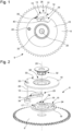
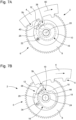
- the mechanism 6 for driving a jumping indicator 4 comprises a wheel plate 8 rotating around a first axis of rotation 20, a drive finger 12 for the indicator and a spring 16.
- the indicator is a date indicator, in particular a date ring comprising an internal toothing 5.
- the indicator is for example an indicator of the minutes, hours, days or months.
- the spring 16 is formed of a first end 17, a coil 18 and a second end 19, the first end being integral in rotation with the wheel plate and the second end being integral in rotation with the drive finger 12 at least during each loading of the spring 16 preceding a jump of the indicator 4 and the driving of the indicator by the mechanism during this jump.
- the first end 17 of the spring is connected to a central part 24 which is integral in rotation with the wheel board 8.
- the spring and the central part form a single piece.
- the mechanism 6 comprises a rigid support 10, which is movable in rotation around the first axis of rotation relative to the wheel board, and a rocker 26 mounted on the rigid support so as to be movable in rotation around a second axis of rotation 22 which is distant from the first axis of rotation 20.
- the second axis of rotation 22 is located at a first end of the lever, which forms the drive finger on the side of its second end.
- the lever has at its first end a circular stud 34 which is inserted into a hole 33, provided in the rigid support, so that the lever can undergo a rotation around the axis of rotation 22 defined by this hole 33, in particular to allow the drive finger 12 to retract during a rapid correction of the date or a certain counterclockwise correction of the time passing through midnight, as will be explained in more detail later.
- the mechanism 6 comprises a central hub 32 defining a shaft which passes through a central hole of the rigid support 10 and guides this rigid support in rotation relative to the wheel board 8, the latter and the central part 24 being driven onto the central hub 32.
- the drive mechanism comprises a first stop which is integral with the rigid support and which limits the rotation of the rocker in a first direction which corresponds to a radial distance of the finger relative to the first axis of rotation 20, the rocker being arranged so as to bear against the first stop at least during loading of the spring before a jump of the indicator and, preferably, also during the driving of the indicator during this jump, and to be able to undergo a rotation in the second direction, opposite to the first direction, and thus allow a radial withdrawal of the drive finger, in the direction of the first axis of rotation 20, under the action of a tangential component, relative to the second axis of rotation 22, of a force exerted on this drive finger by the teeth of the indicator during a correction.
- the spring and the rocker are arranged so that the rocker also bears against the first stop when the spring is not angularly constrained.
- the rigid support comprises a plate which forms the first stop.
- the rigid support is the plate 10.
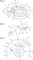
- the rocker 26 is formed by an arm 36 and the drive finger 12, the arm having a first height and being arranged at least partially between the wheel board and the plate.
- the drive finger 12 has a second height H at least in a thick part defining a drive flank 14 intended to come to bear against a tooth of a set of teeth 5 associated with the indicator 4 ( Figures 6A to 8B ) when the indicator is driven by the mechanism 6.
- the second height H is greater than the first height and the thick part of the drive finger is not superimposed on the plate for any useful angular position of the rocker, this thick part extending axially at least partially over the thickness of at least one region of the plate located above the arm.
- the drive flank 14 is substantially radial to the first axis of rotation 20 when the rocker is bearing against the first stop 30.
- the plate 10 has a lateral surface of which a substantially radial zone defines the first stop 30.
- the drive finger 12 has the second height H over its entire extent in the plane of the teeth 5 and is arranged in such a way that its rear upper portion can come to bear against the first stop 30 at least during each loading of the spring, so as to then be held in a fixed angular position relative to the second axis of rotation and thus in a fixed position relative to the first axis of rotation.
- the rear upper portion defines a stop surface 15 which cooperates with the first stop 30 to limit the rotation of the lever in the first direction of rotation, this stop surface 15 being in abutment against the first stop 30 at least during each loading of the spring 16 and a following jump of the indicator, namely a date jump when the time display indicates midnight.
- the plate 10 has a general circular profile with a lateral recess 38, configured to allow the drive finger 12 to penetrate into this recess when a tooth passes along an outer flank 13 of this drive finger and thus to retract, the majority of the spring 16 being covered at all times by the plate.
- the plate 10A of the mechanism 6A comprises: - A central part defining the central hole; - a projecting part 58 which covers a part of the spring 16 on the side of its second end 19 to keep it in the general plane of the spring between the wheel board 8 and the plate 10A; - a part in the form of an annular sector which extends radially from the central part and which defines, at a first angular end, the first stop 30 and, on the side of the second angular end, the hole 33 for the stud 34 of the rocker 26.
- the drive finger 12 has an arcuate outer flank 13 against which at least one tooth 5b of the toothing 5 of the indicator 4 can press during a rapid correction of the indicator by a correction device other than the mechanism, the arcuate outer flank having, while the rocker is in contact with the first stop 30, a radial dimension to the first axis of rotation 20 which is monotonically increasing as it approaches the drive flank 14.
- the rocker 26 has, in an inner portion 46 running along the drive finger 12, a housing 42 having a lateral opening on the side of the spring 16.
- the second end 19 of the spring 16 is extended by a coupling member 40 to the rocker 26, this coupling member 40 being rigid and configured so as to be able to penetrate at least partially into the housing 42 and allow the spring to apply a driving force torque to the rigid support 10 and to the rocker 26 so as to then allow the drive finger 12 to drive the indicator 4.
- the coupling member 40 is configured to be able to penetrate at least partially into the housing 42 through the opening lateral surface of this housing.
- the housing 42 has a lateral surface 52 oriented obliquely in the direction of rotation 50 of the wheel board 8, provided for driving the indicator 4, relative to a radial direction, relative to the central axis of rotation 20, passing through the middle of this lateral surface
- the coupling member 40 has a lateral flank 54, opposite the lateral surface 52, which is also inclined obliquely, relative to the central axis of rotation 20, in the same direction as the lateral surface and which presses at least partially against this lateral surface during said driving of the indicator.
- the lateral surface and the lateral flank have a relatively great length.
- This particular characteristic makes it possible to ensure good maintenance of the coupling member in the housing as soon as the spring 16 is put under tension in contraction.
- the contact point or contact area of the housing on which the spring force is exerted, via the coupling member does not vary during loading of the spring.
- the coupling member 40 cannot rotate on itself, in the direction of rotation of the wheel board, during loading of the spring.
- the rocker 26 advantageously has a lateral ramp 48 on the front part of the inner portion 46 allowing coupling of the coupling member 40 with the rocker 26, in particular with the drive finger, via an introduction of this coupling member into the housing 42, from an angular position of this coupling member located upstream of the lateral ramp 48, by a simple rotation of the plate 10 in a clockwise direction relative to the wheel board 8.
- the housing 42 has a generally triangular shape and opens gradually towards its lateral opening.
- the shape of the part of the coupling member 40 which is inserted into the housing through the lateral opening corresponds substantially to that of the housing.
- This configuration advantageously allows the coupling member to be easily inserted into the housing, but would a priori allow this member to come out quite easily in the event of an impact, although the housing is provided to be relatively deep.
- the spring 16 is arranged so that when this spring is loaded, the coupling member is at a short distance from the inner end 17 of the spring which is rigidly connected to the central part 24. In this situation, the coupling member 40 cannot come out of its housing in the event of an impact.
- the coupling member 40 cannot come out laterally from its housing in the event of an impact.
- the mechanism 6 is arranged so that, when the spring is relaxed or stressed during a loading of this spring preceding a jump of the indicator, the coupling member cannot come out of the housing 42.
- the coupling member 40 may be held, but not necessarily, in this housing by a radial force, relative to the central axis of rotation 20, applied outwards by the spring 16 to this coupling member.
- This radial force (more precisely, the radial component of the force applied by the spring to the lever via the coupling member) is increased during a rapid change of the date or during a correction of the time in a counterclockwise direction and passing through midnight, by the fact that the drive finger and the coupling member then undergo a recoil / withdrawal in the direction of the axis of rotation 20 via a clockwise rotation (second direction of rotation of the lever), so that the coupling member is thus normally held in the housing even when the spring 16 is somewhat forced into expansion in such a situation.
- the coupling finger 12 When the drive finger 12 retracts, by a rotation of the lever 26 in the clockwise direction, during a rapid correction of the date or the time in an anticlockwise direction with passage through midnight, the coupling finger approaches the central part 24 in such a way that the coupling member can no longer, after a certain initial rotation of the rocker, come out of its housing.
- the spring 16 can undergo a certain angular stress in expansion and theoretically allow the coupling member to come out of its housing in the event of an impact.
- the coupling member undergoes an acceleration substantially in the direction of the axis of rotation 20 of the wheel board 8, the rocker then undergoes a certain force torque, which causes a rotation of this rocker around its axis of rotation 22, and the drive finger then follows the coupling member so that the latter remains at least partly in its housing. If the acceleration is in a direction passing substantially through the center of gravity of the rocker and its axis of rotation 22, the coupling member 40 can undergo an exit movement from the housing 42.
- an internal projecting part 44 of the spring can be configured so as to prevent the coupling member from being able to come out completely from its housing.
- a rear portion of the coupling member may be configured so as to collide, during a correction, with a rigid portion secured to the wheel board before being able to completely exit its housing.
- the mechanism 6 is arranged so that the coupling member 40 remains in its housing 42 during normal operation, so that this coupling member is at all times secured to the drive finger during normal operation, and that it cannot in most cases exit its housing during impacts, preferably under no circumstances.
- the mechanism 6 is arranged so that the spring 16 works in contraction when this spring is loaded in order to be able to generate a jump of the indicator.
- an angular displacement of the second end 19 of the spring 16, and thus of the drive finger 12 coupled to the coupling member 40, relative to the wheel board 8 is limited, during a stress of the coil 18 in contraction resulting from the loading of the spring, by a second stop 28, defining an angular stop integral in rotation with the wheel board 8, the indicator and the mechanism being arranged so that a jump of the indicator does not occur, in normal operation, before said angular displacement is stopped by the second stop, at the end of a loading of the spring preceding this jump, and then corresponds to a determined angular distance a (see Figure 6A ).
- the spring 16 comprises an internal projecting part 44 arranged along the coil 18 on the side of its second end 19, this internal projecting part being arranged to come into contact with the second stop 28 (angular stop) and thus end the loading of the spring, then trigger a jump of the indicator 4 to its next stable position, namely to the next date in the case of a date indicator.
- a jump of the indicator occurs before the angular movement of the spring is stopped by the angular stop 28.
- the angular stop is in this case a spring protection stop.
- the drive mechanism does not have an angular stop. The spring works in contraction and the coil of this spring remains free in its development between the two ends of the spring during loading periods.
- the height between the wheel plate 8 and the underside of the teeth 5, including clearance remains constantly located between the lower height and the upper height of the drive finger relative to the wheel plate, including clearance.
- the lower height of the finger is provided to be smaller than the thickness of the teeth of the toothing 5.
- the distance between the upper height of the finger and a dial covering the drive mechanism and the indicator is also provided to be smaller than the thickness of the teeth of the toothing 5.
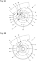
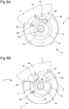
- THE Figures 7A and 7B concern the behavior of the mechanism 6 during a rapid correction of the date ring 4, via a control member that can be manipulated by a user in a conventional manner, in the evening when the wheel board 8 and the plate 10 are for example initially in the configuration of the Figure 7A , so that the finger 12 is located between the tooth 5a and the tooth 5b which precedes it relative to the direction of rotation 60, so that the finger 12 is in the path of the tooth 5b of the indicator.
- the rapid advance of the ring 4 is provided in the direction of rotation 60 corresponding to the single direction of rotation of the date ring.
- the tooth 5b of the toothing 5 comes into contact with the arcuate outer flank 13 of the finger 12 when the ring 4 is rotated and then exerts on this finger a progressively radial force which causes a rotation of the rocker 26, around its axis of rotation 22, in the clockwise direction and thus a movement of the finger 12 in the direction of the central hub of the plate 10, so that the finger undergoes a withdrawal in the direction of the axis of rotation 20.
- This withdrawal is made possible by the configuration of the drive finger 12 and the profile of the lateral recess 38 provided in the plate 10, as well as by the arrangement of the spring 16 and of the central part 24 to which it is fixed and by the configuration of the internal projecting part 44.
- the finger 12 retracts when passing the tooth 5b, leaving this tooth to follow the outer flank 13 of the finger until this tooth angularly exceeds the finger.
- the interaction of the toothing 5 on the drive finger 12 applies a force to the wafer 10 only through the rocker 26, and therefore at the second axis of rotation 22.
- the direction of the force, generated by a tooth 5a or 5b of the indicator pressing on the outer flank 13 of the drive finger, which is applied at the second axis of rotation generates a torque on the wafer, tending to rotate it, which is weaker than in the prior art.
- the rocker 26 can rotate relative to the wafer, under the action of a tooth pressing on the flank outside of the drive finger, without this rigid support performing a significant rotation relative to the wheel board.
- the spring undergoes a mainly radial elastic deformation, relative to the central axis of rotation 20, due to the withdrawal of the drive finger 12 by rotation around the second axis of rotation 22, which is distant from the first axis of rotation 20 (central axis of rotation of the mechanism).
- the drive mechanism 6 therefore makes it possible to perform the same withdrawal of the finger, during a correction, as in the prior art, but it generates a lower elastic deformation of the spring 16 than in the mechanism of the prior art where the spring undergoes, in addition to a radial deformation, a significant angular deformation.
- the work that must be provided by the date ring 4 to the mechanism 6 to allow the passage of a tooth 5b over the drive finger 12 (in a plane perpendicular to the axes of rotation 20 and 22), during the correction in question, is less than in the case of a drive finger with a similar profile but fixed relative to a plate having an oblong hole crossed by a central shaft, in particular formed by a hub, as in the prior art.
- the spring 16 contracts radially and the coupling member 40 moves closer to the central part 24.
- the spring 16 more precisely its coil 18, is also forced to expand a little during the rapid correction of the date ring, simultaneously with the radial stress that the spring undergoes in the direction of the axis of rotation of the wheel plate.
- the stress of the expanding spring is relatively small, or even almost zero depending on the configuration of the system. This is very advantageous for the production of the spring 16 which can thus be arranged to be able to best withstand the contraction occurring during a drive of indicator 4 by device 6, without having to additionally ensure appropriate behavior of this spring for significant expansion stress.
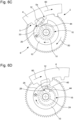
- THE Figures 8A and 8B concern the behavior of the mechanism 6 during a correction of a time displayed by the watch mechanism, which rotates the wheel plate 8, in an anticlockwise direction passing through midnight.
- the date ring 4 remains stationary in the stable position in which it is found during this time correction.
- the succession of states of the mechanism 6 is similar to that which takes place during the rapid correction of the date display described previously.
- Mechanism 6 is configured to prevent jamming during rapid date correction or counterclockwise time correction.
- the invention also relates to a watch comprising a watch movement 2 according to the invention incorporated in a case, this case also incorporating a dial arranged so as to allow the display of data evolving temporally by jumps, in particular the date.
Landscapes
- Physics & Mathematics (AREA)
- General Physics & Mathematics (AREA)
- Electromechanical Clocks (AREA)
Priority Applications (6)
| Application Number | Priority Date | Filing Date | Title |
|---|---|---|---|
| EP23219464.7A EP4575673A1 (de) | 2023-12-21 | 2023-12-21 | Uhrwerk, das mit einem antriebsmechanismus eines sschrittanzeigers ausgestattet ist |
| US18/942,857 US20250208574A1 (en) | 2023-12-21 | 2024-11-11 | Horological movement provided with a mechanism for driving a jumping indicator |
| JP2024198082A JP7741952B2 (ja) | 2023-12-21 | 2024-11-13 | ジャンプインジケーターを駆動する機構を含む時計ムーブメント、および同時計ムーブメントを含む腕時計 |
| KR1020240183666A KR20250097678A (ko) | 2023-12-21 | 2024-12-11 | 점핑 표시기를 구동하기 위한 기구를 구비한 측시 무브먼트 |
| CN202423166270.8U CN223757037U (zh) | 2023-12-21 | 2024-12-20 | 钟表机芯和包括钟表机芯的手表 |
| CN202411890678.1A CN120195949A (zh) | 2023-12-21 | 2024-12-20 | 配备有用于驱动跳动指示器的机构的钟表机芯 |
Applications Claiming Priority (1)
| Application Number | Priority Date | Filing Date | Title |
|---|---|---|---|
| EP23219464.7A EP4575673A1 (de) | 2023-12-21 | 2023-12-21 | Uhrwerk, das mit einem antriebsmechanismus eines sschrittanzeigers ausgestattet ist |
Publications (1)
| Publication Number | Publication Date |
|---|---|
| EP4575673A1 true EP4575673A1 (de) | 2025-06-25 |
Family
ID=89321496
Family Applications (1)
| Application Number | Title | Priority Date | Filing Date |
|---|---|---|---|
| EP23219464.7A Pending EP4575673A1 (de) | 2023-12-21 | 2023-12-21 | Uhrwerk, das mit einem antriebsmechanismus eines sschrittanzeigers ausgestattet ist |
Country Status (5)
| Country | Link |
|---|---|
| US (1) | US20250208574A1 (de) |
| EP (1) | EP4575673A1 (de) |
| JP (1) | JP7741952B2 (de) |
| KR (1) | KR20250097678A (de) |
| CN (2) | CN120195949A (de) |
Citations (7)
| Publication number | Priority date | Publication date | Assignee | Title |
|---|---|---|---|---|
| CH328143A (fr) * | 1956-01-25 | 1958-02-28 | Zenith Montres | Pièce d'horlogerie à quantième à déclenchement semi-instantané |
| CH346170A (fr) * | 1958-04-25 | 1960-04-30 | Roamer Watch Co Sa | Pièce d'horlogerie à quantième |
| FR2325969A2 (fr) * | 1975-09-27 | 1977-04-22 | Pforzheimer Uhren Rohwerke | Dispositif de commande intermittente pour mouvements d'horlogerie avec indication digitale |
| US20020080686A1 (en) * | 2000-12-22 | 2002-06-27 | Eta Sa Fabriques D'ebauches | Instantaneous drive mechanism for a date indicator |
| EP2428855A1 (de) * | 2010-09-08 | 2012-03-14 | Rolex S.A. | Uhrenteil, das eine Vorrichtung zur Anzeige von festgelegten Zeiträumen umfasst |
| CH712222A2 (fr) * | 2016-03-08 | 2017-09-15 | Seiko Instr Inc | Roue d'entraînement d'indicateur de date, mécanisme de calendrier, mouvement et pièce d'horlogerie. |
| EP3828644A1 (de) | 2019-11-27 | 2021-06-02 | ETA SA Manufacture Horlogère Suisse | Uhrwerkdrehteil für semi-momentaner sprungmechanismus |
-
2023
- 2023-12-21 EP EP23219464.7A patent/EP4575673A1/de active Pending
-
2024
- 2024-11-11 US US18/942,857 patent/US20250208574A1/en active Pending
- 2024-11-13 JP JP2024198082A patent/JP7741952B2/ja active Active
- 2024-12-11 KR KR1020240183666A patent/KR20250097678A/ko active Pending
- 2024-12-20 CN CN202411890678.1A patent/CN120195949A/zh active Pending
- 2024-12-20 CN CN202423166270.8U patent/CN223757037U/zh active Active
Patent Citations (7)
| Publication number | Priority date | Publication date | Assignee | Title |
|---|---|---|---|---|
| CH328143A (fr) * | 1956-01-25 | 1958-02-28 | Zenith Montres | Pièce d'horlogerie à quantième à déclenchement semi-instantané |
| CH346170A (fr) * | 1958-04-25 | 1960-04-30 | Roamer Watch Co Sa | Pièce d'horlogerie à quantième |
| FR2325969A2 (fr) * | 1975-09-27 | 1977-04-22 | Pforzheimer Uhren Rohwerke | Dispositif de commande intermittente pour mouvements d'horlogerie avec indication digitale |
| US20020080686A1 (en) * | 2000-12-22 | 2002-06-27 | Eta Sa Fabriques D'ebauches | Instantaneous drive mechanism for a date indicator |
| EP2428855A1 (de) * | 2010-09-08 | 2012-03-14 | Rolex S.A. | Uhrenteil, das eine Vorrichtung zur Anzeige von festgelegten Zeiträumen umfasst |
| CH712222A2 (fr) * | 2016-03-08 | 2017-09-15 | Seiko Instr Inc | Roue d'entraînement d'indicateur de date, mécanisme de calendrier, mouvement et pièce d'horlogerie. |
| EP3828644A1 (de) | 2019-11-27 | 2021-06-02 | ETA SA Manufacture Horlogère Suisse | Uhrwerkdrehteil für semi-momentaner sprungmechanismus |
Also Published As
| Publication number | Publication date |
|---|---|
| CN223757037U (zh) | 2026-01-02 |
| CN120195949A (zh) | 2025-06-24 |
| KR20250097678A (ko) | 2025-06-30 |
| JP2025100361A (ja) | 2025-07-03 |
| US20250208574A1 (en) | 2025-06-26 |
| JP7741952B2 (ja) | 2025-09-18 |
Similar Documents
| Publication | Publication Date | Title |
|---|---|---|
| CH709508A2 (fr) | Mouvement horloger muni d'un mécanisme d'entraînement d'un indicateur analogique à déplacement périodique ou intermittent. | |
| EP2350745B1 (de) | Antriebsmechanismus für ein uhrwerk | |
| EP1770452A1 (de) | Chronometerhemmung für Uhren | |
| EP2264551B1 (de) | Differentialzahnradgetriebe für Uhrwerk | |
| EP4575673A1 (de) | Uhrwerk, das mit einem antriebsmechanismus eines sschrittanzeigers ausgestattet ist | |
| EP2226687B1 (de) | Auskupplungsvorrichtung für Uhrwerksmechanismus und diese Vorrichtung umfassendes Uhrwerk | |
| CH721444A2 (fr) | Mouvement horloger muni d'un mécanisme d'entrainement d'un indicateur sautant | |
| EP1213626B1 (de) | Stossfeste Übertragungsmittel zum Antrieb eines Generators durch eine Schwungmasse, insbesondere in einer Uhr | |
| CH713409B1 (fr) | Balancier pour balancier-spiral du type thermocompensé, balancier-spiral du type thermocompensé, mouvement et pièce d'horlogerie. | |
| EP4575674A1 (de) | Uhrwerk, das mit einem antriebsmechanismus eines sprunganzeigers ausgestattet ist | |
| CH721440A2 (fr) | Mouvement horloger muni d'un mécanisme d'entrainement d'un indicateur sautant | |
| EP3907563B1 (de) | Uhrwerkmechanismus, das ein schwenkorgan umfasst | |
| EP2096504A2 (de) | Mechanismus zur Anzeige der toten Sekunden | |
| CH706543A2 (fr) | Mécanisme d'échappement d'horlogerie. | |
| CH720210B1 (fr) | Mouvement horloger comprenant un mécanisme de commande de quantième | |
| CH720214B1 (fr) | Mécanisme de commande de quantième d'un mouvement horloger | |
| EP2488921B1 (de) | Energiequelle für ein schlagwerk und uhr mit einer derartigen energiequelle | |
| EP4462193B1 (de) | Mechanisches uhrwerk, das ein bewegliches element umfasst, das ein anzeigeelement mit einer bremsvorrichtung umfasst | |
| CH700751B1 (fr) | Mécanisme de chronographe, pièce d'horlogerie munie d'un tel mécanisme et procédé de réglage d'un tel mécanisme. | |
| CH721446A2 (fr) | Mouvement horloger comprenant un élément rigide mobile accouplé à un élément élastique et procédé d'accouplement de ces deux éléments | |
| EP4575676A1 (de) | Uhrwerk, das ein starres bewegliches element umfasst, das mit einem elastischen element gekoppelt ist, und verfahren zum verbinden dieser elemente | |
| EP3112949B1 (de) | Mechanische energiequelle für uhrwerk | |
| EP3855255B1 (de) | Blockiervorrichtung für uhrwerk | |
| EP3783444B1 (de) | Uhrwerkmechanismus, der eine blockiervorrichtung umfasst | |
| EP2515185A1 (de) | Motor mit konstantem Drehmoment |
Legal Events
| Date | Code | Title | Description |
|---|---|---|---|
| PUAI | Public reference made under article 153(3) epc to a published international application that has entered the european phase |
Free format text: ORIGINAL CODE: 0009012 |
|
| STAA | Information on the status of an ep patent application or granted ep patent |
Free format text: STATUS: THE APPLICATION HAS BEEN PUBLISHED |
|
| AK | Designated contracting states |
Kind code of ref document: A1 Designated state(s): AL AT BE BG CH CY CZ DE DK EE ES FI FR GB GR HR HU IE IS IT LI LT LU LV MC ME MK MT NL NO PL PT RO RS SE SI SK SM TR |
|
| P01 | Opt-out of the competence of the unified patent court (upc) registered |
Free format text: CASE NUMBER: APP_31979/2025 Effective date: 20250702 |
|
| STAA | Information on the status of an ep patent application or granted ep patent |
Free format text: STATUS: REQUEST FOR EXAMINATION WAS MADE |
|
| 17P | Request for examination filed |
Effective date: 20260102 |
|
| GRAP | Despatch of communication of intention to grant a patent |
Free format text: ORIGINAL CODE: EPIDOSNIGR1 |
|
| STAA | Information on the status of an ep patent application or granted ep patent |
Free format text: STATUS: GRANT OF PATENT IS INTENDED |
|
| INTG | Intention to grant announced |
Effective date: 20260219 |