EP4575520A1 - Stromwandler mit shunt - Google Patents
Stromwandler mit shunt Download PDFInfo
- Publication number
- EP4575520A1 EP4575520A1 EP23220062.6A EP23220062A EP4575520A1 EP 4575520 A1 EP4575520 A1 EP 4575520A1 EP 23220062 A EP23220062 A EP 23220062A EP 4575520 A1 EP4575520 A1 EP 4575520A1
- Authority
- EP
- European Patent Office
- Prior art keywords
- shunt
- section
- current transducer
- primary conductor
- transducer according
- Prior art date
- Legal status (The legal status is an assumption and is not a legal conclusion. Google has not performed a legal analysis and makes no representation as to the accuracy of the status listed.)
- Pending
Links
Images


Classifications
-
- G—PHYSICS
- G01—MEASURING; TESTING
- G01R—MEASURING ELECTRIC VARIABLES; MEASURING MAGNETIC VARIABLES
- G01R1/00—Details of instruments or arrangements of the types included in groups G01R5/00 - G01R13/00 and G01R31/00
- G01R1/20—Modifications of basic electric elements for use in electric measuring instruments; Structural combinations of such elements with such instruments
- G01R1/203—Resistors used for electric measuring, e.g. decade resistors standards, resistors for comparators, series resistors, shunts
-
- G—PHYSICS
- G01—MEASURING; TESTING
- G01R—MEASURING ELECTRIC VARIABLES; MEASURING MAGNETIC VARIABLES
- G01R31/00—Arrangements for testing electric properties; Arrangements for locating electric faults; Arrangements for electrical testing characterised by what is being tested not provided for elsewhere
- G01R31/36—Arrangements for testing, measuring or monitoring the electrical condition of accumulators or electric batteries, e.g. capacity or state of charge [SoC]
- G01R31/364—Battery terminal connectors with integrated measuring arrangements
Definitions
- the present invention relates to a current transducer based on a shunt resistor.
- One of the known shunt transducer configurations comprises a bus bar, typically in the form of a rectangular profiled bar configured to be clamped or otherwise connected to a primary conductor carrying the current to be measured.
- the bus bar typically has a section of a shunt material such as Manganin - a copper, manganese, nickel alloy - integrally formed and connected to the copper bus bar on either end, whereby the resistance across the shunt material section is measured.
- the shunt material Manganin is used because of it's low temperature coefficient of resistance value and it's long term stability. Thus, there is a higher measurement accuracy over a large range of temperatures compared to copper or other metals and alloys.
- a shunt current transducer that is adapted for the measurement of high currents and has the form of a bus bar that may be coupled to standard circuits provided with bus bar terminal connections.
- a shunt current transducer comprising a primary conductor including a busbar portion with a substantially rectangular cross section, and a measurement processing unit mounted against and connected to the primary conductor, the measurement processing unit comprising a circuit board and a signal processing circuit on the circuit board.
- the primary conductor comprises a plurality of shunt sections connected in series, including at least a first shunt section and a second shunt section, each shunt section bounded by a terminal set arranged at each end of the respective shunt section, said terminal sets comprising terminals formed on the circuit board, the signal processing circuit comprising a first measurement channel connected to the first shunt section and a second measurement channel connected to the second shunt section.
- the first measurement channel comprises a first integrated circuit chip connected to the terminal sets at ends of the first shunt section, and a second integrated circuit chip connected to the terminal sets at ends of the second shunt section.
- the signal processing circuit is configured to cross check measurement values between the first measurement channel and the second measurement channel.
- the material of the first shunt section is different from the material of the second shunt section.
- the material of the first shunt section comprises or consists of a Cu-Ni-Mn alloy, preferably Manganin.
- the material of the second shunt section (4b) is the main material forming the primary conductor.
- the main material forming the primary conductor comprises an alloy with copper of more than 90%, or comprises a copper aluminium alloy.
- At least one of the terminal sets comprises a plurality of terminals greater than five distributed across the width of the associated shunt section substantially in a line.
- the plurality of terminals of a terminal set are spaced part evenly from each other.
- all of the terminal sets comprise a plurality of connection terminals greater than five distributed across the width of the respective shunt sections, orthogonal to the direction of flow of the primary current through the shunt sections.
- each shunt terminal is connected to a resistance, said resistances being connected in parallel to an input of the measurement channel, configured to measure an average value of the voltage difference between ends of the one or at least one shunt section and to determine therefrom the primary current flowing through the one or at least one shunt section.
- the shunt terminals comprise conductive pads formed on the circuit board soldered to the primary conductor.
- first and second shunt sections are directly adjacent each other and comprise a terminal set that forms the interface between the adjacent first and second shunt sections.
- the signal processing circuit comprises a temperature sensor on the circuit board, connected thermally through a metallic via to a the primary conductor.
- the temperature sensor is positioned between terminal sets of one or at least one of the shunt sections.
- the primary conductor comprises transducer terminals configured for a mechanical connection to corresponding terminals of an external primary conductor.
- the primary conductor comprises a third shunt section connected in series to the first and second shunt sections.
- the third shunt section has the same material as the second shunt section, and a different material from the first shunt section which is arranged between the second and third shunt sections.
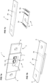
- a shunt current transducer 1 comprises a primary conductor 2 and a measurement processing unit 3 connected to the primary conductor 2 comprising at least a first measurement channel "channel 1" and a second measurement channel “channel 2".
- the primary conductor 2 has a plurality of shunt sections 4 including at least a first shunt section 4a and a second shunt section 4b.
- the measurement processing unit is configured in the first measurement channel to measure a voltage of the first shunt section of the primary conductor and output therefrom a measurement signal representative of a primary current flowing in the primary conductor 2, and the measurement processing unit is configured in the second measurement channel to measure a voltage of the second shunt section of the primary conductor and output therefrom a measurement signal representative of a primary current flowing in the primary conductor 2.
- the primary conductor 2 may in particular have a form of a bus bar, in particular a rectangular cross section bus bar.
- Ends of the shunt sections are connected to and defined by shunt terminals 5 (5a, 5b, 5c, 5d).
- the second shunt section 4b may be directly adjacent the first shunt section 4a.
- there may be only three sets of shunt terminals comprising a first terminal set 5a at a first end of the first shunt section 4a, a second terminal set 5b at an opposed second end of the first shunt section 4a and concurrently at a first end of the second shunt section, and a third terminal set 5c at an opposing second end of the second shunt section.
- the second shunt section 4b may be spaced apart from the first shunt section 4a by a section of primary conductor such that the first shunt section is bounded by first and second terminal sets 5a, 5b and the second shunt section is bounded by third and fourth terminal sets 5c, 5d.
- the first shunt section 4a may, in an advantageous embodiment, comprise a material that is different to the material of the second shunt section 4b.
- the second shunt section 4b may comprise a material that is the same as the material of the first shunt section 4a.
- the material of the first shunt 4a is preferably a material with a low temperature coefficient of resistance value, in particular a Copper Manganese Nickel (Cu-Mn-Ni) alloy such as Manganin (Cu84/Mn12/Ni4 or Cu86/Mn12/Ni2) or Copper Nickel (Cu-Ni) alloy Constantan (Cu55/ /Ni35), that are well known for use in shunt resistors because of their properties of very low temperature coefficient of resistance value.
- Cu-Mn-Ni Copper Manganese Nickel
- NiCr Copper Nickel
- the second shunt section 4b may consist of a material that forms the principal material of the primary conductor, for instance a substantially copper or copper alloy material that is commonly used for bus bars, or alternatively an aluminium alloy.
- a substantially copper or copper alloy material that is commonly used for bus bars
- Materials with low temperature coefficient of resistance values such as Maganin are expensive and are usually placed between common copper parts for mechanical and electrical integrity. Therefore, the use of the material that forms the principal material of the primary conductor, for instance a substantially copper or copper alloy material that is commonly used for bus bars, is advantageous from a cost and mechanical properties perspective.
- the lower cost typical bus bar material parts results in a lower accuracy shunt measurement, but is accurate enough to provide a redundant channel for functional safety applications.
- the shunt sections material is preferably a material with a low temperature coefficient of resistance value as previously mentioned.
- the shunt sections comprise Manganin for the first shunt section which allows to provide a very precise measurement of the voltage (and therefrom the primary current) over a given range of temperatures, the other shunt section formed simply by the main material forming the primary conductor, in particular copper or principally copper based alloy.
- the second shunt section does not provide as precise a measurement output as the first shunt section over a given range of temperatures, it is sufficiently accurate to provide a redundant measurement signal that allows to verify the measurement signal measured across the first shunt section and thus to provide a redundant safety signal to detect malfunction.
- Some or all of the sets of shunt terminals 5 may advantageously comprise a plurality of contact terminals greater than five that span across most of the width of the primary conductor, preferably substantially evenly spaced from each other. There may for instance be a plurality in a range of 5 to 15 terminals in each of one or more more terminal sets.
- the plurality of contact terminals of a set that span across the width of the primary conductor allow to capture the primary current flowing in the primary conductor at different positions distributed across the width of the primary conductor to thus capture a more accurate representation of the mean primary current flowing through the shunt resistance. Measurement inaccuracy stemming from one or two local measurement points in a situation of uneven current density across the width of the primary conductor is thus mitigated.
- Measurement inaccuracies due to uneven current density across the width of the primary conductor is more likely to occur in the material that forms the principal material of the primary conductor, for instance a substantially copper or copper alloy material that is commonly used for bus bars, whereas in materials with low temperature coefficient of resistance values such as Maganin which have a higher resistivity than standard bus bar materials, the current density across the conductor is more homogeneous.
- Manganin or other high resistance conductor materials are used for the shunt section, it may be sufficient to have only one or two terminals on each side of the shunt section, whereas for lower resistivity materials such as common copper alloys for bus bars, it is advantageous to provide the terminal sets on each side of the shunt section with a plurality of contact terminals greater than five, spread across the width of the shunt section.
- the shunt terminals comprise solder pads on the circuit board soldered at corresponding discrete points to the primary conductor, for instance by reflow soldering.
- Reflow soldering may be performed in a standard soldering process for SMD components. The solder pads are separated from each other and the voltages present on those pads are separate inputs to the the analog frontends for processing.
- the plurality of terminals of the terminal set may comprise individual pin terminals that are welded or soldered on to the surface of the primary conductor, or that are inserted with an interference fit in corresponding terminal receiving cavities formed in the primary conductor.
- the terminal sets 5a, 5b arranged at ends of the first shunt section 4a are preferably connected to the main material of the primary conductor at the interface (border) with the first shunt section, rather than connected directly to the material with a low temperature coefficient of resistance value of the first shunt section 4a.
- the measurement processing unit 3 comprises the circuit board 7 and a signal processing circuit 8 on the circuit board 7.
- the circuit board 7 may have conductive pads forming the terminal sets 5 (5a, 5b, 5c, 5d) bounding the first and second shunt sections.
- the terminal sets 5 may comprise circuit pads on the circuit board that are connected in parallel via individual resistors as illustrated in the circuit diagram of figure 2b .
- the current transducer may further comprise at least one temperature sensor 12 configured to measure a temperature of at least one of the shunt sections, to adjust the current measurement value as a function of the measured temperature.
- the temperature sensor may for instance be mounted on the circuit board on a side opposite the side on which the primary conductor is mounted, and thermally connected thereto with a metallic via through the circuit board, soldered to the primary conductor.
- the temperature sensor and via connection is preferably positioned between the first and second terminal sets, for instance approximately at a mid-point 12a between the terminal sets of the corresponding shunt section.
- the measurement of primary current may be performed as follows:
- the signal processing circuit 8 comprises a first measurement channel 9 and a second measurement channel 10, the first measurement channel 9 comprising circuitry for measuring the resistance of the first shunt section 4a, and the second measurement channel 10 comprising circuitry for measuring the resistance of the second shunt section 4b.
- Circuitry for measuring a shunt resistance is per se well known.
- each shunt section 4a, 4b provides an independent measurement output.
- the measurement output of the first channel comprises a measurement of the shunt resistance of the first shunt section 4a processed in a first logic circuit (logic 1)
- the measurement output of the second channel comprises a measurement of the shunt resistance of the second shunt section 4b processed in a second logic circuit (logic 2).
- the first logic circuit is separate from the second logic circuit but the two logic circuits may be interconnected to cross-check the measurement outputs from the logic circuit 1 and the logic circuit 2 in order to determine a malfunction of one of the output circuits.
- the logic circuits may be formed in integrated circuit (IC) chips, Each measurement channel may comprise its own integrated circuit chip, the first measurement channel 9 having a first IC chip 11a and the second measurement channel 10 having a second IC chip 11b.
- the separate IC chips, one for each measurement channel, provide greater independence between the two channels and therefore a higher safety. Both IC chips may be mounted and interconnected to the same circuit board 7.
- the circuit board may be assembled along, adjacent and against the primary conductor bus bar 2 and have a width that is substantially the same, or within 20% greater or smaller than the primary conductor width so as to form a compact current transducer arrangement.
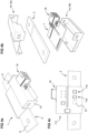
- the primary conductor may be provided with transducer terminals 6 for instance in a form of holes as well known for clamping on a bolt and nut connection.
- transducer terminals 6 for instance in a form of holes as well known for clamping on a bolt and nut connection.
- other per se well known interconnection methods with or without the provision of holes, for instance by clamping welding, or soldering, may be provided in variants.
- the primary conductor may have a non-planar shape, for instance with a bent section, and where the transducer terminals 6a, 6b are not necessarily aligned, for instance as illustrated in figure 3b .
- Various configurations of the bus bar may be provided to adapt to the devices and primary conductor configuration of the device to which they are intended to be coupled.
- One or a plurality of the current transducers may be integrated directly within an electrical system of a device with one or more electrical phases, or may be provided as an individual component for assembly and connection to external devices.
- the current transducer 1 comprises an insulating housing 14 surrounding the shunt sections and portion of the circuit board mounted against the shunt sections, and a connector 16 for pluggable connection to a connector of an external device for power and measurement signal communication.
- the current transducer may advantageously be implemented in a battery current measurement system, for instance of an electric vehicle.
Landscapes
- Physics & Mathematics (AREA)
- General Physics & Mathematics (AREA)
- Measuring Instrument Details And Bridges, And Automatic Balancing Devices (AREA)
Priority Applications (1)
| Application Number | Priority Date | Filing Date | Title |
|---|---|---|---|
| EP23220062.6A EP4575520A1 (de) | 2023-12-22 | 2023-12-22 | Stromwandler mit shunt |
Applications Claiming Priority (1)
| Application Number | Priority Date | Filing Date | Title |
|---|---|---|---|
| EP23220062.6A EP4575520A1 (de) | 2023-12-22 | 2023-12-22 | Stromwandler mit shunt |
Publications (1)
| Publication Number | Publication Date |
|---|---|
| EP4575520A1 true EP4575520A1 (de) | 2025-06-25 |
Family
ID=89321694
Family Applications (1)
| Application Number | Title | Priority Date | Filing Date |
|---|---|---|---|
| EP23220062.6A Pending EP4575520A1 (de) | 2023-12-22 | 2023-12-22 | Stromwandler mit shunt |
Country Status (1)
| Country | Link |
|---|---|
| EP (1) | EP4575520A1 (de) |
Cited By (1)
| Publication number | Priority date | Publication date | Assignee | Title |
|---|---|---|---|---|
| CN120993012A (zh) * | 2025-09-30 | 2025-11-21 | 新沂市鑫洋电子有限公司 | 一种锰铜分流器组件及智能电表 |
Citations (8)
| Publication number | Priority date | Publication date | Assignee | Title |
|---|---|---|---|---|
| EP2981833B1 (de) * | 2013-04-05 | 2017-01-25 | Isabellenhütte Heusler GmbH & Co. Kg | Messwiderstand und entsprechendes messverfahren |
| US20170089955A1 (en) * | 2014-09-25 | 2017-03-30 | Sanyo Electric Co., Ltd. | Electrical current detection device equipped with shunt resistor, and power supply device |
| WO2021014872A1 (ja) * | 2019-07-25 | 2021-01-28 | 株式会社Gsユアサ | 電流計測装置、電流の計測方法、蓄電装置及び抵抗器 |
| DE102020111634B3 (de) * | 2020-04-29 | 2021-04-01 | Isabellenhütte Heusler Gmbh & Co. Kg | Strommesswiderstand |
| DE112019004609T5 (de) * | 2018-09-14 | 2021-05-27 | Koa Corporation | Stromerfassungsvorrichtung |
| DE102019218308A1 (de) * | 2019-11-26 | 2021-05-27 | Continental Automotive Gmbh | Widerstandsbaugruppe für Stromsensor sowie Stromsensor und Verfahren zur Messung eines Batteriestroms |
| EP3851859A1 (de) * | 2020-01-17 | 2021-07-21 | Wieland-Werke AG | Widerstandsanordnung, messschaltung mit einer widerstandsanordnung sowie verfahren zur herstallung eines bandförmigen werkstoffverbundes für eine widerstandsanordnung |
| DE102021210139A1 (de) * | 2021-09-14 | 2023-03-16 | Volkswagen Aktiengesellschaft | Messkörper für ein Ermitteln einer Funktionalität eines Bordnetzes eines Fahrzeuges sowie Fahrzeug |
-
2023
- 2023-12-22 EP EP23220062.6A patent/EP4575520A1/de active Pending
Patent Citations (8)
| Publication number | Priority date | Publication date | Assignee | Title |
|---|---|---|---|---|
| EP2981833B1 (de) * | 2013-04-05 | 2017-01-25 | Isabellenhütte Heusler GmbH & Co. Kg | Messwiderstand und entsprechendes messverfahren |
| US20170089955A1 (en) * | 2014-09-25 | 2017-03-30 | Sanyo Electric Co., Ltd. | Electrical current detection device equipped with shunt resistor, and power supply device |
| DE112019004609T5 (de) * | 2018-09-14 | 2021-05-27 | Koa Corporation | Stromerfassungsvorrichtung |
| WO2021014872A1 (ja) * | 2019-07-25 | 2021-01-28 | 株式会社Gsユアサ | 電流計測装置、電流の計測方法、蓄電装置及び抵抗器 |
| DE102019218308A1 (de) * | 2019-11-26 | 2021-05-27 | Continental Automotive Gmbh | Widerstandsbaugruppe für Stromsensor sowie Stromsensor und Verfahren zur Messung eines Batteriestroms |
| EP3851859A1 (de) * | 2020-01-17 | 2021-07-21 | Wieland-Werke AG | Widerstandsanordnung, messschaltung mit einer widerstandsanordnung sowie verfahren zur herstallung eines bandförmigen werkstoffverbundes für eine widerstandsanordnung |
| DE102020111634B3 (de) * | 2020-04-29 | 2021-04-01 | Isabellenhütte Heusler Gmbh & Co. Kg | Strommesswiderstand |
| DE102021210139A1 (de) * | 2021-09-14 | 2023-03-16 | Volkswagen Aktiengesellschaft | Messkörper für ein Ermitteln einer Funktionalität eines Bordnetzes eines Fahrzeuges sowie Fahrzeug |
Cited By (1)
| Publication number | Priority date | Publication date | Assignee | Title |
|---|---|---|---|---|
| CN120993012A (zh) * | 2025-09-30 | 2025-11-21 | 新沂市鑫洋电子有限公司 | 一种锰铜分流器组件及智能电表 |
Similar Documents
| Publication | Publication Date | Title |
|---|---|---|
| KR100600441B1 (ko) | 저항 장치, 저항 장치의 제조방법 및 측정 회로 | |
| US12248005B2 (en) | Shunt resistor and manufacturing method thereof | |
| EP4145471B1 (de) | Shunt-widerstand, shunt-widerstand-herstellungsverfahren und stromdetektionsvorrichtung | |
| US6646430B1 (en) | Current measuring shunt with circuitry mounted thereon | |
| KR20190040198A (ko) | 고전류 범위의 전류를 측정하기 위한 측정 장치 | |
| KR20120047925A (ko) | 전자부품 및 그의 제조방법 | |
| JP7173755B2 (ja) | シャント抵抗器の実装構造 | |
| CN107533891A (zh) | 电流检测装置 | |
| JP2021114603A (ja) | 抵抗装置、抵抗装置を備えた測定回路ならびに抵抗装置用の帯状材料複合体の作製方法 | |
| EP2257823B1 (de) | Strommessgerät mit shunt-widerstand und kühlkörper | |
| CN109416375A (zh) | 电流测定装置 | |
| EP4575520A1 (de) | Stromwandler mit shunt | |
| WO2023135977A1 (ja) | 電流検出装置およびその製造方法 | |
| US7385828B2 (en) | Electronic shunt resistor assembly | |
| CN114076843B (zh) | 电流传感器元件、电流传感器单元和测量电流的方法 | |
| CN110174540B (zh) | 分流电阻器的测量系统 | |
| US20250216421A1 (en) | Shunt resistor and current detection apparatus | |
| CN116264120B (zh) | 分流电阻器以及电流检测装置 | |
| CN115915590B (zh) | 用于测量电池驱动式车辆的电池电流的印刷电路板组件 | |
| CN222529416U (zh) | 具有分流器和磁场检测器的电流换能器 | |
| US20250102542A1 (en) | Current measuring device and associated production method | |
| CN111354522A (zh) | 用于电池传感器的电阻组件和电池传感器 | |
| CN120322833A (zh) | 分流电阻器 | |
| EP4431950B1 (de) | Stromsensoranordnung und verfahren zum bestimmen einer temperatur einer widerstandsanordnung | |
| CN107923952A (zh) | 具有高机械坚固性的电池传感器单元 |
Legal Events
| Date | Code | Title | Description |
|---|---|---|---|
| PUAI | Public reference made under article 153(3) epc to a published international application that has entered the european phase |
Free format text: ORIGINAL CODE: 0009012 |
|
| STAA | Information on the status of an ep patent application or granted ep patent |
Free format text: STATUS: THE APPLICATION HAS BEEN PUBLISHED |
|
| AK | Designated contracting states |
Kind code of ref document: A1 Designated state(s): AL AT BE BG CH CY CZ DE DK EE ES FI FR GB GR HR HU IE IS IT LI LT LU LV MC ME MK MT NL NO PL PT RO RS SE SI SK SM TR |
|
| STAA | Information on the status of an ep patent application or granted ep patent |
Free format text: STATUS: REQUEST FOR EXAMINATION WAS MADE |
|
| 17P | Request for examination filed |
Effective date: 20251011 |
|
| GRAP | Despatch of communication of intention to grant a patent |
Free format text: ORIGINAL CODE: EPIDOSNIGR1 |
|
| STAA | Information on the status of an ep patent application or granted ep patent |
Free format text: STATUS: GRANT OF PATENT IS INTENDED |
|
| RIC1 | Information provided on ipc code assigned before grant |
Ipc: G01R 1/20 20060101AFI20260121BHEP Ipc: G01R 31/364 20190101ALI20260121BHEP |
|
| INTG | Intention to grant announced |
Effective date: 20260203 |
|
| GRAS | Grant fee paid |
Free format text: ORIGINAL CODE: EPIDOSNIGR3 |
|
| GRAA | (expected) grant |
Free format text: ORIGINAL CODE: 0009210 |
|
| STAA | Information on the status of an ep patent application or granted ep patent |
Free format text: STATUS: THE PATENT HAS BEEN GRANTED |