EP4575441A2 - Druckmessgeräte, druckbehälteranordnungen und verfahren zur anzeige von druck in druckbehälteranordnungen - Google Patents
Druckmessgeräte, druckbehälteranordnungen und verfahren zur anzeige von druck in druckbehälteranordnungen Download PDFInfo
- Publication number
- EP4575441A2 EP4575441A2 EP25174490.0A EP25174490A EP4575441A2 EP 4575441 A2 EP4575441 A2 EP 4575441A2 EP 25174490 A EP25174490 A EP 25174490A EP 4575441 A2 EP4575441 A2 EP 4575441A2
- Authority
- EP
- European Patent Office
- Prior art keywords
- helical tube
- compensation member
- pressure
- pressure gauge
- closed end
- Prior art date
- Legal status (The legal status is an assumption and is not a legal conclusion. Google has not performed a legal analysis and makes no representation as to the accuracy of the status listed.)
- Pending
Links
Images


Classifications
-
- G—PHYSICS
- G01—MEASURING; TESTING
- G01L—MEASURING FORCE, STRESS, TORQUE, WORK, MECHANICAL POWER, MECHANICAL EFFICIENCY, OR FLUID PRESSURE
- G01L19/00—Details of, or accessories for, apparatus for measuring steady or quasi-steady pressure of a fluent medium insofar as such details or accessories are not special to particular types of pressure gauges
- G01L19/04—Means for compensating for effects of changes of temperature, i.e. other than electric compensation
-
- G—PHYSICS
- G01—MEASURING; TESTING
- G01L—MEASURING FORCE, STRESS, TORQUE, WORK, MECHANICAL POWER, MECHANICAL EFFICIENCY, OR FLUID PRESSURE
- G01L7/00—Measuring the steady or quasi-steady pressure of a fluid or a fluent solid material by mechanical or fluid pressure-sensitive elements
- G01L7/02—Measuring the steady or quasi-steady pressure of a fluid or a fluent solid material by mechanical or fluid pressure-sensitive elements in the form of elastically-deformable gauges
- G01L7/04—Measuring the steady or quasi-steady pressure of a fluid or a fluent solid material by mechanical or fluid pressure-sensitive elements in the form of elastically-deformable gauges in the form of flexible, deformable tubes, e.g. Bourdon gauges
- G01L7/041—Construction or mounting of deformable tubes
-
- G—PHYSICS
- G01—MEASURING; TESTING
- G01L—MEASURING FORCE, STRESS, TORQUE, WORK, MECHANICAL POWER, MECHANICAL EFFICIENCY, OR FLUID PRESSURE
- G01L7/00—Measuring the steady or quasi-steady pressure of a fluid or a fluent solid material by mechanical or fluid pressure-sensitive elements
- G01L7/02—Measuring the steady or quasi-steady pressure of a fluid or a fluent solid material by mechanical or fluid pressure-sensitive elements in the form of elastically-deformable gauges
- G01L7/04—Measuring the steady or quasi-steady pressure of a fluid or a fluent solid material by mechanical or fluid pressure-sensitive elements in the form of elastically-deformable gauges in the form of flexible, deformable tubes, e.g. Bourdon gauges
- G01L7/043—Measuring the steady or quasi-steady pressure of a fluid or a fluent solid material by mechanical or fluid pressure-sensitive elements in the form of elastically-deformable gauges in the form of flexible, deformable tubes, e.g. Bourdon gauges with mechanical transmitting or indicating means
-
- G—PHYSICS
- G01—MEASURING; TESTING
- G01L—MEASURING FORCE, STRESS, TORQUE, WORK, MECHANICAL POWER, MECHANICAL EFFICIENCY, OR FLUID PRESSURE
- G01L7/00—Measuring the steady or quasi-steady pressure of a fluid or a fluent solid material by mechanical or fluid pressure-sensitive elements
- G01L7/02—Measuring the steady or quasi-steady pressure of a fluid or a fluent solid material by mechanical or fluid pressure-sensitive elements in the form of elastically-deformable gauges
- G01L7/04—Measuring the steady or quasi-steady pressure of a fluid or a fluent solid material by mechanical or fluid pressure-sensitive elements in the form of elastically-deformable gauges in the form of flexible, deformable tubes, e.g. Bourdon gauges
- G01L7/048—Measuring the steady or quasi-steady pressure of a fluid or a fluent solid material by mechanical or fluid pressure-sensitive elements in the form of elastically-deformable gauges in the form of flexible, deformable tubes, e.g. Bourdon gauges correcting or regulating means for flexible, deformable tubes
-
- G—PHYSICS
- G01—MEASURING; TESTING
- G01L—MEASURING FORCE, STRESS, TORQUE, WORK, MECHANICAL POWER, MECHANICAL EFFICIENCY, OR FLUID PRESSURE
- G01L7/00—Measuring the steady or quasi-steady pressure of a fluid or a fluent solid material by mechanical or fluid pressure-sensitive elements
- G01L7/02—Measuring the steady or quasi-steady pressure of a fluid or a fluent solid material by mechanical or fluid pressure-sensitive elements in the form of elastically-deformable gauges
- G01L7/04—Measuring the steady or quasi-steady pressure of a fluid or a fluent solid material by mechanical or fluid pressure-sensitive elements in the form of elastically-deformable gauges in the form of flexible, deformable tubes, e.g. Bourdon gauges
- G01L7/045—Measuring the steady or quasi-steady pressure of a fluid or a fluent solid material by mechanical or fluid pressure-sensitive elements in the form of elastically-deformable gauges in the form of flexible, deformable tubes, e.g. Bourdon gauges with optical transmitting or indicating means
Definitions
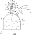
- the present disclosure relates generally to measuring fluid pressure, and more particularly to measuring expellant pressure in fire suppression cylinders.
- Pressure gauges such as inspection pressure gauges in fire suppression cylinders, are commonly used to indicate the pressure of fluids contained within pressure vessels.
- Such pressure gauges generally include a mechanical element coupling the pressurized fluid with a needle.
- the pressure of the expellant drives the needle to a location within the pressure gauge indicating that the fire suppression cylinder is ready for use.
- the needle typically inhabits a location within the pressure gauge indicative that the fire suppression cylinder is not ready for use.
- One challenge to using a pressure gauge to indicate readiness of a fire suppression cylinder is the effect of temperature on the expellant contained within the fire suppression cylinder. Specifically, because temperature of the expellant contained within the fire suppression cylinder can alter the expellant pressure, some pressure gauges can indicate low pressure when the fire suppression cylinder has neither leaked nor been discharged. To avoid unnecessary replacement or recharge due to temperature-induced pressure changes, technicians typically correct the displayed pressure for the ambient temperature when inspecting such cylinders; however, this introduces the risk that additional human error may be introduced into the inspection of fire suppression agent cylinders.
- a pressure gauge is provided.
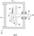
- the pressure gauge includes a housing having an inlet, a helical tube arranged within the housing with a closed end and an open end, the open end of the helical tube in fluid communication with the inlet, and a compensation member.
- the compensation member is arranged between the between the open end and the closed end of the helical tube, the compensation member fixed to the helical tube.
- the compensation member and the helical tube are formed from materials having different coefficients of thermal expansion to limit movement of the closed end of the helical tube due to temperature change of a compressed fluid in fluid communication with the helical tube.
- further embodiments of the pressure gauge may include that the compensation member is directly connected to the helical tube.
- further embodiments of the pressure gauge may include that the compensation member is indirectly connected to the helical tube.
- further embodiments of the pressure gauge may include that the compensation member is connected along an entirety of the helical tube.
- further embodiments of the pressure gauge may include that the compensation member is connected along only a portion of the helical tube.
- further embodiments of the pressure gauge may include that the portion is at a location proximate the open end of the helical tube.
- further embodiments of the pressure gauge may include that the portion is at a location proximate the closed end on the helical tube.
- further embodiments of the pressure gauge may include that the helical tube thermally couples the compensation member to the compressed fluid.
- further embodiments of the pressure gauge may include a compressed fluid including an expellant impounded within the helical tube.
- further embodiments of the pressure gauge may include that the open end of the helical tube is fixed relative to the housing, and that the free of the of the helical tube is free relative to the housing, and wherein the helical tube has an oblong profile
- further embodiments of the pressure gauge may include that the compensation member is a beam.
- further embodiments of the pressure gauge may include that the helical tube is a bourdon tube.
- a pressure vessel assembly is also provided.
- the pressure vessel assembly includes a pressure vessel defining a chamber and having a boss and a pressure gauge as described above seated in the boss and in fluid communication therethrough with the chamber of the pressure vessel.
- a compressed fluid including an expellant and a fire suppression material is contained with the chamber of the pressure vessel, a portion of the compressed fluid impounded within the helical tube.
- the pointer 122 is fixed to the closed end 142 of the helical tube 124 and is movable therewith according to pressure of the compressed fluid 108 communicated to the open end 140 of the helical tube 124.
- the pointer 122 is registered relative to the scale 120 according to pressure of the compressed fluid 108 communicated to the open end 140 of the helical tube 124.
- the pointer 122 overlays the scale 120 and the window 118 overlays the pointer 122, the pointer 122 arranged between the scale 120 and the window 118.
- the pressure gauge 100 can be configured such that the pressure of the compressed fluid 108 communicated to the helical tube 124 for a predetermined mass of the compressed fluid 108 at a predetermined nominal temperature register the pointer 122 to the ready segment 136 of the scale 120, the pressure gauge 100 thereby providing a ready-to-use indication 148.
- pressure of the compressed fluid 108 (shown in FIG. 1 ) communicated to the helical tube 124 can change with temperature of the compressed fluid 108.
- temperature-induced pressure change can displace the pointer 122 from the ready segment 136 of the scale 120.
- the pressure communicated by the compressed fluid 108 to the helical tube 124 can displace the pointer 122 such that the pointer 122 becomes registered to the under-pressure segment 132 of the scale 120 - the pressure gauge 100 potentially providing an under-pressure indication 150 (shown with dashed pointer outline) that the pressure vessel assembly 102 has developed a leak and is therefore unserviceable when the pressure vessel assembly 102 is in fact ready-to-use.
- the pressure communicated to the helical tube 124 can displace the pointer 122 such that the pointer 122 becomes registered to the over-pressure segment 134 of the scale 120 - the pressure gauge 100 potentially providing an over-pressure indication 152 (also shown with dashed pointer outline) that the pressure vessel assembly 102 is overcharged when the pressure vessel assembly 102 is in fact properly charged.
- the pressure gauge 100 includes the compensation member 126.
- the helical tube 124 impounds within its interior a portion of the compressed fluid 108 between the open end 140 (shown in FIG. 2 ) and the closed end 142 (shown in FIG. 2 ) of the helical tube 124 and is formed by the helical tube material 144.
- the compensation member 126 is fixed to the helical tube 124 between the open end 140 and the closed end 142 of the helical tube 124 such that the helical tube 124 thermally couples the compressed fluid 108 to the compensation member 126 and is formed from a compensation member material 154.
- the compensation member material 154 be different than the helical tube material 144. More specifically, it is contemplated that the helical tube material 144 have a coefficient of thermal expansion 160 that is different than a coefficient of thermal expansion 164 of the compensation member material 154.
- the compensation member material 154 and the helical tube material 144 can both be metallic materials, the helical tube 124 and the compensation member 126 thereby defining a bimetallic beam 190 containing the compressed fluid 108. It is contemplated that the coefficient of thermal expansion 164 of the compensation member material 154 be such that compensation member 126 opposes (and in certain embodiments prevents entirely) movement of the closed end 142 (shown in FIG. 2 ) of the helical tube 124 due to change in temperature of the compressed fluid 108, e.g., via communication of heat H between the compensation member 126 and the compressed fluid 108 through the helical tube 124.
- suitable helical tube materials include stainless steel, brass, and bronze materials.
- suitable compensation member materials include stainless steel, brass, bronze, and/or aluminum materials differing in composition from that of the helical tube material 144.
- the compensation member 126 can be directly connected to the helical tube 124, such as through a deposition technique. Direct connection of the compensation member 126 to the helical tube 124 limits thermal resistance between the compressed fluid 108 and the compensation member 126, limiting delay in response of the compensation member 126 to temperature change of the helical tube 124.
- the compensation member 126 can be indirectly connected to the helical tube 124, such as by a braze or weld 162. Indirect connection of the compensation member 126 to the helical tube 124 can simplify the manufacture of the pressure gauge 100.
- the compensation member 126 can be connected to the helical tube 124 along substantially the entirety of the helical tube 124, e.g., being conformally disposed thereon or connected thereto by the braze or weld 162 (shown in FIG. 4 ). Connecting the helical tube 124 along substantially the entirety of the helical tube 124 (i.e. the entire length of the helical tube) provides a relative uniform balancing to the offsetting contraction and expansion of the helical tube 124 and the compensation member 126 in response to a change of the compressed fluid 108 along the helical tube, limiting strain with the helical tube.
- the compensation member 126 can be connected to only a portion of the helical tube 124, by the braze or weld 162 (shown in FIG. 4 ).
- the compensation member 126 can be connected to the helical tube 124 at a location 166 proximate the open end 140 of the helical tube 124, the compensation member 126 exaggerating the offsetting force applied by the compensation member 126 to the helical tube 124.
- the compensation member 126 can the connected to the helical tube 124 at a location 168 proximate the closed end 142 of the helical tube 124, limiting exaggeration of the offsetting force exerted on the helical tube 124 by the compensation member 126.
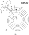
- FIGS. 3 , 5 , and 6 cooperation of the compensation member 126 and the helical tube 124 is shown.
- pressure of the compressed fluid 108 is communicated to the helical tube 124 by the inlet conduit 128 (shown in FIG. 2 ). Since the helical tube 124 is closed on one end the pressure of the compressed fluid 108 is operative to displace the closed end 142 of the helical tube 124 according to magnitude of the pressure of the compressed fluid 108.
- the pressure causes the helical tube 124 to position the pointer 122 along the ready segment 136 of the scale 120.
- decrease in pressure of the compressed fluid 108 e.g., from a decrease in the mass of compressed fluid 108 due to actuation of the discharge valve 106 (shown in FIG. 1 ) or leakage from the pressure vessel 104 (shown in FIG. 1 ), exerts a deformation force 180 on the helical tube 124.
- the deformation force 180 urges the helical tube 124 to become more tightly wound according to the magnitude of the deformation force 180, diameter of the turns of the helical tube 124 tending to decrease.
- the resulting deformation displaces the closed end 142 of the helical tube 124, and thereby the pointer 122, toward the under-pressure segment 132 of the scale 120.
- the pressure gauge 100 indicates the decrease in the mass of the compressed fluid 108 contained within the pressure vessel 104 with deflection 170 of the pointer 122 relative to the scale 120 in the direction of the under-pressure indication 150 (shown in FIG. 3 ).
- the compensation member 126 exerts a deformation compensation force 186 in opposition to the deformation force 180.
- the compensation member material 154 shown in FIG. 4
- the compensation member material 154 contracts more slowly than the helical tube material 144 (shown in FIG. 4 ) forming the helical tube 124.
- the slower rate of contraction of the compensation member material 154 relative to that of the helical tube material 144 causes the compensation member 126 to exert the deformation compensation force 186 on the helical tube 124.
- the deformation compensation force 186 is exerted in a direction opposite that of the deformation force 180, the deformation compensation force 186 thereby limiting movement of the closed end 142 of the helical tube 124. Consequently, the pointer 122 remains in registration with the ready segment 136 of the scale 120 and does not move into registration with the under-pressure segment 132 of the scale 120, as would otherwise occur in response to the temperature decrease.
- the closed end 142 exhibits substantially no movement due to pressure change within the pressure vessel 104 due to temperature change within a range of about -40 degrees Celsius (about -40 degrees Fahrenheit) and about 55 degrees Celsius (about 131 degrees Fahrenheit). Absence of movement within this range can prevent temperature changes within a range commonly experienced by fire suppression cylinders from displaying a decrease in mass of the compressed fluid 108 contained within the pressure vessel 104 when, in fact, the mass of the compressed fluid 108 contained within the pressure vessel 104 (shown in FIG. 1 ) is unchanged.
- increase in pressure of the compressed fluid 108 exerts a deformation force 182 on the helical tube 124.
- the deformation force 182 urges the helical tube 124 to become less tightly wound according to the magnitude of the deformation force 182.
- the resulting deformation of the helical tube 124 displaces 172 the closed end 142 of the helical tube 124, and thereby the pointer 122, toward the over-pressure segment 134 of the scale 120.
- the pressure gauge 100 thereby indicates an increase in the mass of the compressed fluid 108 contained within the pressure vessel 104 with registration of the pointer 122 along the over-pressure segment 134 of the scale 120.
- the compensation member 126 exerts a deformation compensation force 184 in opposition to the deformation force 182. Specifically, as temperature of the compressed fluid 108 increases, the compensation member material 154 (shown in FIG. 4 ) forming the compensation member 126 expands at a rate different than that of the helical tube material 144 (shown in FIG. 4 ) forming the helical tube 124 in response to the temperature increase.
- the different rates of expansion in response to the temperature increase causes the compensation member 126 to exert the deformation compensation force 184 on the helical tube 124 in a direction opposite the deformation force 182, also limiting movement of the closed end 142 of the helical tube 124. Consequently, the pointer 122 remains in registration with the ready segment 136 of the scale 120 and does not move into registration with the over-pressure segment 134 of the scale 120, as would otherwise occur due to the temperature increase.
- the closed end 142 exhibits substantially no movement due to pressure change within the pressure vessel 104 due to temperature change within a range of about -40 degrees Celsius (about -40 degrees Fahrenheit) and about 55 degrees Celsius (about 131 degrees Fahrenheit).
- absence of movement within this range can prevent temperature changes within a range commonly experienced by fire suppression cylinders from displaying an increase in mass of the compressed fluid 108 contained within the pressure vessel 104 when no mass has been added to the chamber 114 (shown in FIG. 1 ) of the pressure vessel 104 (shown in FIG. 1 ).
- Pressure gauges can be employed on fire suppression cylinders to provide indication of pressure within the fire suppression cylinder, such as due to actuation of the fire suppression cylinder and/or leakage from the fire suppression cylinder.
- the pressure displayed by a pressure gauge can be influenced by factors other than actuation and/or leakage, such as pressure change due to temperature change of the fire suppression cylinder. In such event a fire suppression cylinder that is otherwise ready for use can appear to be in either an under-pressure or over-pressure condition. This can result in unnecessary service and/or replacement of the fire suppression cylinder.
- pressure gauges with compensation members are employed to understate or overstate pressure reported by pressure gauges when pressure change within the fire suppression cylinder is due to change in temperature relative to a nominal temperature.
- the compensation member is directly connected to helical tube, e.g., between an open end and a closed end of a helical tube, the compensation member and the helical tube thereby cooperating as a bimetallic beam.
- the material forming the compensation member and the shape of the compensation member are selected such that the closed end of the helical tube does not move in response to temperature-driven temperature changes within a range of between about -40 degrees Celsius (about -40 degrees Fahrenheit) and about 55 degrees Celsius (about 131 degrees Fahrenheit), the compensation member thereby preventing temperature change a fire suppression from suggesting that the fire suppression cylinder has been overfilled, actuated and/or leaked.
Landscapes
- Physics & Mathematics (AREA)
- General Physics & Mathematics (AREA)
- Measuring Fluid Pressure (AREA)
Applications Claiming Priority (3)
| Application Number | Priority Date | Filing Date | Title |
|---|---|---|---|
| US201962892816P | 2019-08-28 | 2019-08-28 | |
| EP20771669.7A EP4022274B1 (de) | 2019-08-28 | 2020-08-24 | Druckmessgeräte, druckbehälteranordnungen und verfahren zur druckanzeige in druckbehälteranordnungen |
| PCT/US2020/047608 WO2021041302A1 (en) | 2019-08-28 | 2020-08-24 | Pressure gauges, pressure vessel assemblies, and methods of displaying pressure within pressure vessel assemblies |
Related Parent Applications (1)
| Application Number | Title | Priority Date | Filing Date |
|---|---|---|---|
| EP20771669.7A Division EP4022274B1 (de) | 2019-08-28 | 2020-08-24 | Druckmessgeräte, druckbehälteranordnungen und verfahren zur druckanzeige in druckbehälteranordnungen |
Publications (2)
| Publication Number | Publication Date |
|---|---|
| EP4575441A2 true EP4575441A2 (de) | 2025-06-25 |
| EP4575441A3 EP4575441A3 (de) | 2025-09-03 |
Family
ID=72473959
Family Applications (2)
| Application Number | Title | Priority Date | Filing Date |
|---|---|---|---|
| EP25174490.0A Pending EP4575441A3 (de) | 2019-08-28 | 2020-08-24 | Druckmessgeräte, druckbehälteranordnungen und verfahren zur anzeige von druck in druckbehälteranordnungen |
| EP20771669.7A Active EP4022274B1 (de) | 2019-08-28 | 2020-08-24 | Druckmessgeräte, druckbehälteranordnungen und verfahren zur druckanzeige in druckbehälteranordnungen |
Family Applications After (1)
| Application Number | Title | Priority Date | Filing Date |
|---|---|---|---|
| EP20771669.7A Active EP4022274B1 (de) | 2019-08-28 | 2020-08-24 | Druckmessgeräte, druckbehälteranordnungen und verfahren zur druckanzeige in druckbehälteranordnungen |
Country Status (4)
| Country | Link |
|---|---|
| US (1) | US11835408B2 (de) |
| EP (2) | EP4575441A3 (de) |
| ES (1) | ES3032387T3 (de) |
| WO (1) | WO2021041302A1 (de) |
Families Citing this family (2)
| Publication number | Priority date | Publication date | Assignee | Title |
|---|---|---|---|---|
| JP1670498S (de) * | 2020-04-01 | 2020-10-19 | ||
| CN119959071B (zh) * | 2025-04-03 | 2025-08-26 | 朗松珂利(上海)仪器仪表有限公司 | 自补偿波纹管及自补偿式气体密度测量装置 |
Family Cites Families (8)
| Publication number | Priority date | Publication date | Assignee | Title |
|---|---|---|---|---|
| GB190924370A (en) * | 1909-10-23 | 1910-04-21 | Schaeffer And Budenberg Ltd | Improvements in Pressure Gauges. |
| GB191424370A (en) | 1914-04-21 | 1915-04-21 | William John Vincent | A New or Improved Method of Adjusting the Throw of Variable Throw Eccentrics. |
| US1798645A (en) * | 1926-03-08 | 1931-03-31 | Taylor Instrument Co | Bourdon-spring unit |
| DE2358649A1 (de) | 1972-12-06 | 1974-06-12 | Haenni & Cie Ag | Durch stoerende umgebungstemperaturaenderungen beeinflusste messeinrichtung |
| US4143545A (en) * | 1978-01-03 | 1979-03-13 | Htl Industries, Inc. | Pressure gauge assembly |
| US4682501A (en) * | 1985-04-11 | 1987-07-28 | Thomas Walker | Temperature compensated Bourdon tube gauge |
| US10288514B2 (en) | 2015-12-15 | 2019-05-14 | Anderson Instrument Co., Inc. | System and method for reducing thermal offset in a pressure gauge |
| US11366035B2 (en) * | 2019-10-15 | 2022-06-21 | Anderson Instrument Co., Inc. | System and method for reducing thermal offset in a pressure gauge |
-
2020
- 2020-08-24 US US15/734,861 patent/US11835408B2/en active Active
- 2020-08-24 ES ES20771669T patent/ES3032387T3/es active Active
- 2020-08-24 WO PCT/US2020/047608 patent/WO2021041302A1/en not_active Ceased
- 2020-08-24 EP EP25174490.0A patent/EP4575441A3/de active Pending
- 2020-08-24 EP EP20771669.7A patent/EP4022274B1/de active Active
Also Published As
| Publication number | Publication date |
|---|---|
| ES3032387T3 (en) | 2025-07-18 |
| US11835408B2 (en) | 2023-12-05 |
| EP4022274B1 (de) | 2025-05-28 |
| WO2021041302A1 (en) | 2021-03-04 |
| EP4022274A1 (de) | 2022-07-06 |
| EP4575441A3 (de) | 2025-09-03 |
| US20220187151A1 (en) | 2022-06-16 |
Similar Documents
| Publication | Publication Date | Title |
|---|---|---|
| US11835408B2 (en) | Pressure gauges, pressure vessel assemblies, and methods of displaying pressure within pressure vessel assemblies | |
| EP2516976B1 (de) | Ermüdungsbeständige tauchhülse und verfahren | |
| EP2333509A1 (de) | Präzisionsdosenbarometer mit einer Kapillarröhre als ein Druckanzeiger | |
| US3990309A (en) | Temperature compensated pressure limited gauge | |
| US20200056954A1 (en) | Overpressure protection system | |
| JP2010529454A (ja) | 差圧センサ | |
| JP2010529454A5 (de) | ||
| US11566956B2 (en) | Pressure sensor for a pipe | |
| JP2021113698A (ja) | 温度指示計 | |
| Rousseaux et al. | A static method for determination of vapour—liquid equilibria and saturated liquid molar volumes at high pressures and temperatures using a new variable-volume cell | |
| US10288514B2 (en) | System and method for reducing thermal offset in a pressure gauge | |
| US11573163B2 (en) | Density monitor with integrated low pressure indicator | |
| WO2015153842A1 (en) | Method for replacing a process measurement instrument | |
| US3934479A (en) | Measurement apparatus influenced by disturbing ambient temperature fluctuations | |
| KR101078177B1 (ko) | 과압안전밸브를 구비한 압력측정장치 | |
| US7117740B2 (en) | Remote visual liquid quantity indicator | |
| US11366035B2 (en) | System and method for reducing thermal offset in a pressure gauge | |
| US3067614A (en) | Apparatus for indicating pressure in fluid system | |
| CN113758522A (zh) | 一种气源装置用机械式温度压力对照表 | |
| US20210025773A1 (en) | Manometer | |
| US4267890A (en) | Fire extinguishing system including sensor comparable to determine charge | |
| JP2017173149A (ja) | 水素残量センサ | |
| RU2656765C1 (ru) | Способ определения остатков рабочего тела-газа в емкостях рабочей системы с высоким давлением | |
| EP3006769B1 (de) | Einstufige, getrennte gas-fluid-stossdämpferwartung | |
| EP3671163B1 (de) | Druckanzeige zur messung eines druckunterschiedes zwischen zwei flüssigkeiten |
Legal Events
| Date | Code | Title | Description |
|---|---|---|---|
| PUAI | Public reference made under article 153(3) epc to a published international application that has entered the european phase |
Free format text: ORIGINAL CODE: 0009012 |
|
| STAA | Information on the status of an ep patent application or granted ep patent |
Free format text: STATUS: THE APPLICATION HAS BEEN PUBLISHED |
|
| AC | Divisional application: reference to earlier application |
Ref document number: 4022274 Country of ref document: EP Kind code of ref document: P |
|
| AK | Designated contracting states |
Kind code of ref document: A2 Designated state(s): AL AT BE BG CH CY CZ DE DK EE ES FI FR GB GR HR HU IE IS IT LI LT LU LV MC MK MT NL NO PL PT RO RS SE SI SK SM TR |
|
| REG | Reference to a national code |
Ref country code: DE Ref legal event code: R079 Free format text: PREVIOUS MAIN CLASS: G01L0019040000 Ipc: G01L0007040000 |
|
| PUAL | Search report despatched |
Free format text: ORIGINAL CODE: 0009013 |
|
| AK | Designated contracting states |
Kind code of ref document: A3 Designated state(s): AL AT BE BG CH CY CZ DE DK EE ES FI FR GB GR HR HU IE IS IT LI LT LU LV MC MK MT NL NO PL PT RO RS SE SI SK SM TR |
|
| RIC1 | Information provided on ipc code assigned before grant |
Ipc: G01L 7/04 20060101AFI20250728BHEP Ipc: G01L 19/04 20060101ALI20250728BHEP |
|
| P01 | Opt-out of the competence of the unified patent court (upc) registered |
Free format text: CASE NUMBER: UPC_APP_2338_4575441/2025 Effective date: 20250804 |