EP4022274B1 - Druckmessgeräte, druckbehälteranordnungen und verfahren zur druckanzeige in druckbehälteranordnungen - Google Patents
Druckmessgeräte, druckbehälteranordnungen und verfahren zur druckanzeige in druckbehälteranordnungen Download PDFInfo
- Publication number
- EP4022274B1 EP4022274B1 EP20771669.7A EP20771669A EP4022274B1 EP 4022274 B1 EP4022274 B1 EP 4022274B1 EP 20771669 A EP20771669 A EP 20771669A EP 4022274 B1 EP4022274 B1 EP 4022274B1
- Authority
- EP
- European Patent Office
- Prior art keywords
- helical tube
- pressure
- compensation member
- pressure gauge
- pointer
- Prior art date
- Legal status (The legal status is an assumption and is not a legal conclusion. Google has not performed a legal analysis and makes no representation as to the accuracy of the status listed.)
- Active
Links
Images


Classifications
-
- G—PHYSICS
- G01—MEASURING; TESTING
- G01L—MEASURING FORCE, STRESS, TORQUE, WORK, MECHANICAL POWER, MECHANICAL EFFICIENCY, OR FLUID PRESSURE
- G01L19/00—Details of, or accessories for, apparatus for measuring steady or quasi-steady pressure of a fluent medium insofar as such details or accessories are not special to particular types of pressure gauges
- G01L19/04—Means for compensating for effects of changes of temperature, i.e. other than electric compensation
-
- G—PHYSICS
- G01—MEASURING; TESTING
- G01L—MEASURING FORCE, STRESS, TORQUE, WORK, MECHANICAL POWER, MECHANICAL EFFICIENCY, OR FLUID PRESSURE
- G01L7/00—Measuring the steady or quasi-steady pressure of a fluid or a fluent solid material by mechanical or fluid pressure-sensitive elements
- G01L7/02—Measuring the steady or quasi-steady pressure of a fluid or a fluent solid material by mechanical or fluid pressure-sensitive elements in the form of elastically-deformable gauges
- G01L7/04—Measuring the steady or quasi-steady pressure of a fluid or a fluent solid material by mechanical or fluid pressure-sensitive elements in the form of elastically-deformable gauges in the form of flexible, deformable tubes, e.g. Bourdon gauges
- G01L7/041—Construction or mounting of deformable tubes
-
- G—PHYSICS
- G01—MEASURING; TESTING
- G01L—MEASURING FORCE, STRESS, TORQUE, WORK, MECHANICAL POWER, MECHANICAL EFFICIENCY, OR FLUID PRESSURE
- G01L7/00—Measuring the steady or quasi-steady pressure of a fluid or a fluent solid material by mechanical or fluid pressure-sensitive elements
- G01L7/02—Measuring the steady or quasi-steady pressure of a fluid or a fluent solid material by mechanical or fluid pressure-sensitive elements in the form of elastically-deformable gauges
- G01L7/04—Measuring the steady or quasi-steady pressure of a fluid or a fluent solid material by mechanical or fluid pressure-sensitive elements in the form of elastically-deformable gauges in the form of flexible, deformable tubes, e.g. Bourdon gauges
- G01L7/043—Measuring the steady or quasi-steady pressure of a fluid or a fluent solid material by mechanical or fluid pressure-sensitive elements in the form of elastically-deformable gauges in the form of flexible, deformable tubes, e.g. Bourdon gauges with mechanical transmitting or indicating means
-
- G—PHYSICS
- G01—MEASURING; TESTING
- G01L—MEASURING FORCE, STRESS, TORQUE, WORK, MECHANICAL POWER, MECHANICAL EFFICIENCY, OR FLUID PRESSURE
- G01L7/00—Measuring the steady or quasi-steady pressure of a fluid or a fluent solid material by mechanical or fluid pressure-sensitive elements
- G01L7/02—Measuring the steady or quasi-steady pressure of a fluid or a fluent solid material by mechanical or fluid pressure-sensitive elements in the form of elastically-deformable gauges
- G01L7/04—Measuring the steady or quasi-steady pressure of a fluid or a fluent solid material by mechanical or fluid pressure-sensitive elements in the form of elastically-deformable gauges in the form of flexible, deformable tubes, e.g. Bourdon gauges
- G01L7/048—Measuring the steady or quasi-steady pressure of a fluid or a fluent solid material by mechanical or fluid pressure-sensitive elements in the form of elastically-deformable gauges in the form of flexible, deformable tubes, e.g. Bourdon gauges correcting or regulating means for flexible, deformable tubes
-
- G—PHYSICS
- G01—MEASURING; TESTING
- G01L—MEASURING FORCE, STRESS, TORQUE, WORK, MECHANICAL POWER, MECHANICAL EFFICIENCY, OR FLUID PRESSURE
- G01L7/00—Measuring the steady or quasi-steady pressure of a fluid or a fluent solid material by mechanical or fluid pressure-sensitive elements
- G01L7/02—Measuring the steady or quasi-steady pressure of a fluid or a fluent solid material by mechanical or fluid pressure-sensitive elements in the form of elastically-deformable gauges
- G01L7/04—Measuring the steady or quasi-steady pressure of a fluid or a fluent solid material by mechanical or fluid pressure-sensitive elements in the form of elastically-deformable gauges in the form of flexible, deformable tubes, e.g. Bourdon gauges
- G01L7/045—Measuring the steady or quasi-steady pressure of a fluid or a fluent solid material by mechanical or fluid pressure-sensitive elements in the form of elastically-deformable gauges in the form of flexible, deformable tubes, e.g. Bourdon gauges with optical transmitting or indicating means
Definitions
- the present invention relates to a pressure gauge and to a pressure vessel assembly including the pressure gauge as well as to a related method.
- the present disclosure relates generally to measuring fluid pressure, and more particularly to measuring expellant pressure in fire suppression cylinders.
- Pressure gauges such as inspection pressure gauges in fire suppression cylinders, are commonly used to indicate the pressure of fluids contained within pressure vessels.
- Such pressure gauges generally include a mechanical element coupling the pressurized fluid with a needle.
- the pressure of the expellant drives the needle to a location within the pressure gauge indicating that the fire suppression cylinder is ready for use.
- the needle typically inhabits a location within the pressure gauge indicative that the fire suppression cylinder is not ready for use.
- One challenge to using a pressure gauge to indicate readiness of a fire suppression cylinder is the effect of temperature on the expellant contained within the fire suppression cylinder. Specifically, because temperature of the expellant contained within the fire suppression cylinder can alter the expellant pressure, some pressure gauges can indicate low pressure when the fire suppression cylinder has neither leaked nor been discharged. To avoid unnecessary replacement or recharge due to temperature-induced pressure changes, technicians typically correct the displayed pressure for the ambient temperature when inspecting such cylinders; however, this introduces the risk that additional human error may be introduced into the inspection of fire suppression agent cylinders.
- GB 1909 24,370 A discloses a pressure gauge using a compensating strip combined with, and having a different coefficient of expansion to, a Bourdon tube.
- US 3,934,479 A discloses a pressure gauge that similarly comprises a compensation element, in the form of a filler body within the Bourdon tube.
- Another known pressure gauge is disclosed in US 1,798,645 A .
- a pressure gauge includes a housing having an inlet, a helical tube arranged within the housing with a closed end and an open end, the open end of the helical tube in fluid communication with the inlet, and a compensation member.
- the compensation member is arranged between the open end and the closed end of the helical tube, the compensation member fixed to the helical tube.
- the compensation member and the helical tube are formed from materials having different coefficients of thermal expansion to limit movement of the closed end of the helical tube due to temperature change of a compressed fluid in fluid communication with the helical tube.
- the compensation member is a bimetallic beam. The compensation member is connected along an entirety of the helical tube.
- the pressure gauge may include that the compensation member is directly connected to the helical tube.
- the pressure gauge may include that the compensation member is indirectly connected to the helical tube.
- the pressure gauge may include that the helical tube thermally couples the compensation member to the compressed fluid.
- the pressure gauge may include a compressed fluid including an expellant impounded within the helical tube.
- the pressure gauge may include that the open end of the helical tube is fixed relative to the housing, and that the free of the of the helical tube is free relative to the housing, and wherein the helical tube has an oblong profile.
- the pressure gauge may include a pointer fixed relative to the closed end of the helical tube, a scale underlying the pointer, and a window seated in the housing and overlying the pointer.
- the scale has an under-pressure segment coupled to an over-pressure segment by a ready segment.
- the pressure gauge may include that the helical tube is a bourdon tube.
- a pressure vessel assembly is also provided.
- the pressure vessel assembly includes a pressure vessel defining a chamber and having a boss and a pressure gauge as described above seated in the boss and in fluid communication therethrough with the chamber of the pressure vessel.
- a compressed fluid including an expellant and a fire suppression material is contained with the chamber of the pressure vessel, a portion of the compressed fluid impounded within the helical tube.
- the pressure vessel assembly may include a pointer fixed relative to the closed end of the helical tube, a scale underlying the pointer, and a window seated in the housing and overlying the pointer.
- the scale has an under-pressure segment coupled to an over-pressure segment by a ready segment.
- the pointer remains fixed relative to the scale over a temperature range of between about between about -40 degrees Celsius (about -40 degrees Fahrenheit) and about 55 degrees Celsius (about 131 degrees Fahrenheit).
- a method of making a pressure gauge includes defining a housing having an inlet, arranging a helical tube within the housing with a closed end and an open end such that the open end of the helical tube is in fluid communication with the inlet, and arranging a compensation member arranged between the open end and the closed end of the helical tube such that the compensation member is fixed to the helical tube.
- the compensation member and the helical tube are formed from materials having different coefficients of thermal expansion to limit movement of the closed end of the helical tube due to temperature change of a compressed fluid in fluid communication with the helical tube.
- the compensation member is a bimetallic beam. The compensation member is connected along an entirety of the helical tube.
- FIG. 1 a partial view of an exemplary embodiment of a pressure gauge constructed in accordance with the disclosure is shown in FIG. 1 and is designated generally by reference character 100.
- FIGS. 2-6 Other embodiments of pressure gauges, pressure vessel assemblies, and methods of displaying pressure within pressure vessel assemblies in accordance with the present disclosure, or aspects thereof, are provided in FIGS. 2-6 , as will be described.
- the systems and methods described herein can be used for displaying temperature-compensated pressure within pressure vessels, such as in pressure gauges employed on fire suppression cylinders for leak detection, though the present disclosure is not limited to leak detection or to fire suppression cylinders in general.
- a pressure vessel assembly 102 e.g., a fire suppression cylinder
- the pressure vessel assembly 102 includes the pressure gauge 100, a pressure vessel 104, a discharge valve 106, and a compressed fluid 108.
- the pressure vessel 104 has a wall 110 and a boss 112.
- the wall 110 defines a chamber 114 within the pressure vessel 104.
- the compressed fluid 108 is disposed within the chamber 114 and the discharge valve 106 is in fluid communication with the chamber 114 for selective coupling of the chamber 114 with the external environment 10.
- the selective coupling of the chamber 114 to the discharge valve 106 allows for issue of the compressed fluid 108 therethrough to the external environment 10 upon actuation of the discharge valve 106.
- the compressed fluid 108 includes an expellant 12 and a fire suppression material 14.
- the pressure gauge 100 is seated on the boss 112 and is in fluid communication therethrough with the compressed fluid 108.
- the pressure gauge 100 includes a housing 116, a window 118, and a scale 120.
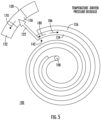
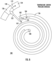
- the pressure gauge 100 also includes a pointer 122, a helical tube 124, a compensation member 126 (shown in FIG. 3 ), and an inlet conduit 128.
- the housing 116 has an interior 130 (shown in FIG. 2 ).
- the window 118 is seated in the housing 116 and is formed from a transparent material, such as glass or plastic.
- the scale 120 is supported within the housing 116 and is fixed relative to the housing 116.
- the pointer 122 is movably supported within the interior 130 of the housing 116 and is registered to the scale 120 according to pressure of the compressed fluid 108.
- the scale 120 has an under-pressure segment 132 coupled to an over-pressure segment 134 by a ready segment 136.
- pressure gauges having other types of scales can also benefit from the present disclosure, such as pressure gauges having graduated scales and colored indicators by way of non-limiting example.
- the housing 116 has an inlet 138 defined by the inlet conduit 128.
- the inlet 138 is in fluid communication with the chamber 114 (show in FIG. 1 ) for communication of pressure of the compressed fluid 108, and in certain embodiments the compressed fluid 108, to the pressure gauge 100.
- the inlet conduit 128 in turn extends into the interior 130 of the housing 116 and is in fluid communication with the helical tube 124.
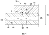
- the helical tube 124 has an open end 140 and a closed end 142 and is formed from a helical tube material 144 (shown in FIG. 4 ).
- the open end 140 of the helical tube 124 is fixed relative to the housing 116 and is connected to the inlet conduit 128.
- the closed end 142 is free relative to the housing 116 and is fixed thereto the pointer 122.
- the helical tube 124 defines an oblong profile 146 (shown in FIG. 3 ).
- the helical tube 124 can be a bourdon tube.
- the pointer 122 is fixed to the closed end 142 of the helical tube 124 and is movable therewith according to pressure of the compressed fluid 108 communicated to the open end 140 of the helical tube 124.
- the pointer 122 is registered relative to the scale 120 according to pressure of the compressed fluid 108 communicated to the open end 140 of the helical tube 124.
- the pointer 122 overlays the scale 120 and the window 118 overlays the pointer 122, the pointer 122 arranged between the scale 120 and the window 118.
- the pressure gauge 100 can be configured such that the pressure of the compressed fluid 108 communicated to the helical tube 124 for a predetermined mass of the compressed fluid 108 at a predetermined nominal temperature register the pointer 122 to the ready segment 136 of the scale 120, the pressure gauge 100 thereby providing a ready-to-use indication 148.
- pressure of the compressed fluid 108 (shown in FIG. 1 ) communicated to the helical tube 124 can change with temperature of the compressed fluid 108.
- temperature-induced pressure change can displace the pointer 122 from the ready segment 136 of the scale 120.
- the pressure communicated by the compressed fluid 108 to the helical tube 124 can displace the pointer 122 such that the pointer 122 becomes registered to the under-pressure segment 132 of the scale 120 - the pressure gauge 100 potentially providing an under-pressure indication 150 (shown with dashed pointer outline) that the pressure vessel assembly 102 has developed a leak and is therefore unserviceable when the pressure vessel assembly 102 is in fact ready-to-use.
- the pressure communicated to the helical tube 124 can displace the pointer 122 such that the pointer 122 becomes registered to the over-pressure segment 134 of the scale 120 - the pressure gauge 100 potentially providing an over-pressure indication 152 (also shown with dashed pointer outline) that the pressure vessel assembly 102 is overcharged when the pressure vessel assembly 102 is in fact properly charged.
- the pressure gauge 100 includes the compensation member 126.
- the helical tube 124 impounds within its interior a portion of the compressed fluid 108 between the open end 140 (shown in FIG. 2 ) and the closed end 142 (shown in FIG. 2 ) of the helical tube 124 and is formed by the helical tube material 144.
- the compensation member 126 is fixed to the helical tube 124 between the open end 140 and the closed end 142 of the helical tube 124 such that the helical tube 124 thermally couples the compressed fluid 108 to the compensation member 126 and is formed from a compensation member material 154.
- the compensation member material 154 is different than the helical tube material 144. More specifically, the helical tube material 144 has a coefficient of thermal expansion 160 that is different than a coefficient of thermal expansion 164 of the compensation member material 154.
- the compensation member material 154 and the helical tube material 144 can both be metallic materials, the helical tube 124 and the compensation member 126 thereby defining a bimetallic beam 190 containing the compressed fluid 108. It is contemplated that the coefficient of thermal expansion 164 of the compensation member material 154 be such that compensation member 126 opposes (and in certain embodiments prevents entirely) movement of the closed end 142 (shown in FIG. 2 ) of the helical tube 124 due to change in temperature of the compressed fluid 108, e.g., via communication of heat H between the compensation member 126 and the compressed fluid 108 through the helical tube 124.
- suitable helical tube materials include stainless steel, brass, and bronze materials.
- suitable compensation member materials include stainless steel, brass, bronze, and/or aluminum materials differing in composition from that of the helical tube material 144.
- the compensation member 126 can be directly connected to the helical tube 124, such as through a deposition technique. Direct connection of the compensation member 126 to the helical tube 124 limits thermal resistance between the compressed fluid 108 and the compensation member 126, limiting delay in response of the compensation member 126 to temperature change of the helical tube 124.
- the compensation member 126 can be indirectly connected to the helical tube 124, such as by a braze or weld 162. Indirect connection of the compensation member 126 to the helical tube 124 can simplify the manufacture of the pressure gauge 100.
- the compensation member 126 is connected to the helical tube 124 along substantially the entirety of the helical tube 124, e.g., being conformally disposed thereon or connected thereto by the braze or weld 162 (shown in FIG. 4 ). Connecting the helical tube 124 along substantially the entirety of the helical tube 124 (i.e. the entire length of the helical tube) provides a relative uniform balancing to the offsetting contraction and expansion of the helical tube 124 and the compensation member 126 in response to a change of the compressed fluid 108 along the helical tube, limiting strain with the helical tube.
- FIGS. 3 , 5 , and 6 cooperation of the compensation member 126 and the helical tube 124 is shown.
- pressure of the compressed fluid 108 is communicated to the helical tube 124 by the inlet conduit 128 (shown in FIG. 2 ). Since the helical tube 124 is closed on one end the pressure of the compressed fluid 108 is operative to displace the closed end 142 of the helical tube 124 according to magnitude of the pressure of the compressed fluid 108.
- the pressure causes the helical tube 124 to position the pointer 122 along the ready segment 136 of the scale 120.
- decrease in pressure of the compressed fluid 108 e.g., from a decrease in the mass of compressed fluid 108 due to actuation of the discharge valve 106 (shown in FIG. 1 ) or leakage from the pressure vessel 104 (shown in FIG. 1 ), exerts a deformation force 180 on the helical tube 124.
- the deformation force 180 urges the helical tube 124 to become more tightly wound according to the magnitude of the deformation force 180, diameter of the turns of the helical tube 124 tending to decrease.
- the resulting deformation displaces the closed end 142 of the helical tube 124, and thereby the pointer 122, toward the under-pressure segment 132 of the scale 120.
- the pressure gauge 100 indicates the decrease in the mass of the compressed fluid 108 contained within the pressure vessel 104 with deflection 170 of the pointer 122 relative to the scale 120 in the direction of the under-pressure indication 150 (shown in FIG. 3 ).
- the compensation member 126 exerts a deformation compensation force 186 in opposition to the deformation force 180.
- the compensation member material 154 shown in FIG. 4
- the compensation member material 154 contracts more slowly than the helical tube material 144 (shown in FIG. 4 ) forming the helical tube 124.
- the slower rate of contraction of the compensation member material 154 relative to that of the helical tube material 144 causes the compensation member 126 to exert the deformation compensation force 186 on the helical tube 124.
- the deformation compensation force 186 is exerted in a direction opposite that of the deformation force 180, the deformation compensation force 186 thereby limiting movement of the closed end 142 of the helical tube 124. Consequently, the pointer 122 remains in registration with the ready segment 136 of the scale 120 and does not move into registration with the under-pressure segment 132 of the scale 120, as would otherwise occur in response to the temperature decrease.
- the closed end 142 exhibits substantially no movement due to pressure change within the pressure vessel 104 due to temperature change within a range of about -40 degrees Celsius (about -40 degrees Fahrenheit) and about 55 degrees Celsius (about 131 degrees Fahrenheit). Absence of movement within this range can prevent temperature changes within a range commonly experienced by fire suppression cylinders from displaying a decrease in mass of the compressed fluid 108 contained within the pressure vessel 104 when, in fact, the mass of the compressed fluid 108 contained within the pressure vessel 104 (shown in FIG. 1 ) is unchanged.
- increase in pressure of the compressed fluid 108 exerts a deformation force 182 on the helical tube 124.
- the deformation force 182 urges the helical tube 124 to become less tightly wound according to the magnitude of the deformation force 182.
- the resulting deformation of the helical tube 124 displaces 172 the closed end 142 of the helical tube 124, and thereby the pointer 122, toward the over-pressure segment 134 of the scale 120.
- the pressure gauge 100 thereby indicates an increase in the mass of the compressed fluid 108 contained within the pressure vessel 104 with registration of the pointer 122 along the over-pressure segment 134 of the scale 120.
- the compensation member 126 exerts a deformation compensation force 184 in opposition to the deformation force 182. Specifically, as temperature of the compressed fluid 108 increases, the compensation member material 154 (shown in FIG. 4 ) forming the compensation member 126 expands at a rate different than that of the helical tube material 144 (shown in FIG. 4 ) forming the helical tube 124 in response to the temperature increase.
- the different rates of expansion in response to the temperature increase causes the compensation member 126 to exert the deformation compensation force 184 on the helical tube 124 in a direction opposite the deformation force 182, also limiting movement of the closed end 142 of the helical tube 124. Consequently, the pointer 122 remains in registration with the ready segment 136 of the scale 120 and does not move into registration with the over-pressure segment 134 of the scale 120, as would otherwise occur due to the temperature increase.
- the closed end 142 exhibits substantially no movement due to pressure change within the pressure vessel 104 due to temperature change within a range of about -40 degrees Celsius (about -40 degrees Fahrenheit) and about 55 degrees Celsius (about 131 degrees Fahrenheit).
- absence of movement within this range can prevent temperature changes within a range commonly experienced by fire suppression cylinders from displaying an increase in mass of the compressed fluid 108 contained within the pressure vessel 104 when no mass has been added to the chamber 114 (shown in FIG. 1 ) of the pressure vessel 104 (shown in FIG. 1 ).
- Pressure gauges can be employed on fire suppression cylinders to provide indication of pressure within the fire suppression cylinder, such as due to actuation of the fire suppression cylinder and/or leakage from the fire suppression cylinder.
- the pressure displayed by a pressure gauge can be influenced by factors other than actuation and/or leakage, such as pressure change due to temperature change of the fire suppression cylinder. In such event a fire suppression cylinder that is otherwise ready for use can appear to be in either an under-pressure or over-pressure condition. This can result in unnecessary service and/or replacement of the fire suppression cylinder.
- pressure gauges with compensation members are employed to understate or overstate pressure reported by pressure gauges when pressure change within the fire suppression cylinder is due to change in temperature relative to a nominal temperature.
- the compensation member is directly connected to helical tube, e.g., between an open end and a closed end of a helical tube, the compensation member and the helical tube thereby cooperating as a bimetallic beam.
- the material forming the compensation member and the shape of the compensation member are selected such that the closed end of the helical tube does not move in response to temperature-driven temperature changes within a range of between about -40 degrees Celsius (about -40 degrees Fahrenheit) and about 55 degrees Celsius (about 131 degrees Fahrenheit), the compensation member thereby preventing temperature change a fire suppression from suggesting that the fire suppression cylinder has been overfilled, actuated and/or leaked.
Landscapes
- Physics & Mathematics (AREA)
- General Physics & Mathematics (AREA)
- Measuring Fluid Pressure (AREA)
Claims (11)
- Druckmessgerät (100), umfassend:ein Gehäuse (116), das einen Einlass (138) aufweist;ein Wendelrohr (124), das innerhalb des Gehäuses mit einem geschlossenen Ende (142) und einem offenen Ende (140) angeordnet ist, wobei das offene Ende des Wendelrohrs in Fluidverbindung mit dem Einlass steht; undein Ausgleichselement (126), das zwischen dem offenen Ende und dem geschlossenen Ende des Wendelrohrs angeordnet ist, wobei das Ausgleichselement an dem Wendelrohr fixiert ist,wobei das Ausgleichselement und das Wendelrohr (124) aus Materialien (144, 154) gebildet sind, die unterschiedliche Wärmeausdehnungskoeffizienten (160, 164) aufweisen, um die Bewegung des geschlossenen Endes (142) des Wendelrohrs aufgrund der Temperaturänderung eines komprimierten Fluids (108), das in Fluidverbindung mit dem Wendelrohr steht, zu beschränken; unddas Ausgleichselement (126) ein Bimetallbalken ist,dadurch gekennzeichnet, dass:
das Ausgleichselement (126) entlang des gesamten Wendelrohrs (124) mit dem Wendelrohr (124) verbunden ist. - Druckmessgerät nach Anspruch 1, wobei das Ausgleichselement (126) direkt mit dem Wendelrohr (124) verbunden ist.
- Druckmessgerät nach Anspruch 1, wobei das Ausgleichselement (126) indirekt mit dem Wendelrohr (124) verbunden ist.
- Druckmessgerät nach Anspruch 1, wobei das Wendelrohr (124) das Ausgleichselement (126) thermisch mit dem komprimierten Fluid (108) koppelt.
- Druckmessgerät nach Anspruch 1, ferner umfassend ein komprimiertes Fluid (108), das ein Treibmittel (12) einschließt, das sich innerhalb des Wendelrohrs (124) staut.
- Druckmessgerät nach Anspruch 1, wobei das offene Ende (140) des Wendelrohrs (124) relativ zu dem Gehäuse (116) fixiert ist, wobei das geschlossene Ende (142) des Wendelrohrs relativ zu dem Gehäuse frei ist und wobei das Wendelrohr ein längliches Profil (146) aufweist.
- Druckmessgerät nach Anspruch 1, ferner umfassend:einen Zeiger (122), der relativ zu dem geschlossenen Ende (142) des Wendelrohrs (124) fixiert ist;eine Waage (120), die unter dem Zeiger liegt, wobei die Waage ein Unterdrucksegment (132) aufweist, das durch ein Bereitschaftssegment (136) mit einem Überdrucksegment (134) gekoppelt ist; undein Fenster (118), das in dem Gehäuse (116) sitzt und über dem Zeiger (122) liegt.
- Druckmessgerät nach Anspruch 1, wobei das Wendelrohr (124) ein Bourdon-Rohr ist.
- Druckbehälteranordnung (102), umfassend:einen Druckbehälter (104), der eine Kammer (114) definiert und eine Nabe (112) aufweist;ein Druckmessgerät (100) nach Anspruch 1, das in der Nabe sitzt und dadurch mit der Kammer des Druckbehälters in Fluidverbindung steht; undein komprimiertes Fluid (108), das ein Treibmittel (12) und ein Feuerlöschmaterial (13) einschließt, das in der Kammer (114) des Druckbehälters (104) enthalten ist, wobei sich ein Teil des komprimierten Fluids innerhalb des Wendelrohrs (124) staut.
- Druckbehälter nach Anspruch 9, wobei das Druckmessgerät (100) Folgendes einschließt:einen Zeiger (122), der relativ zu dem geschlossenen Ende (142) des Wendelrohrs fixiert ist;eine Waage (120), die unter dem Zeiger liegt, wobei die Waage ein Unterdrucksegment (132) aufweist, das durch ein Bereitschaftssegment (136) mit einem Überdrucksegment (134) gekoppelt ist; undein Fenster (118), das in dem Gehäuse (116) sitzt und über dem Zeiger (122) liegt,wobei der Zeiger relativ zu der Waage (120) über einen Temperaturbereich von zwischen etwa -40 Grad Celsius (etwa -40 Grad Fahrenheit) und etwa 55 Grad Celsius (etwa 131 Grad Fahrenheit) fixiert bleibt.
- Verfahren zum Herstellen eines Druckmessgeräts (100), umfassend:Definieren eines Gehäuses (116), das einen Einlass (138) aufweist;Anordnen eines Wendelrohrs (124) innerhalb des Gehäuses mit einem geschlossenen Ende (142) und einem offenen Ende (140), wobei das offene Ende des Wendelrohrs in Fluidverbindung mit dem Einlass steht; undAnordnen eines Ausgleichselements (126), das zwischen dem offenen Ende und dem geschlossenen Ende des Wendelrohrs angeordnet ist, wobei das Ausgleichselement an dem Wendelrohr fixiert ist,wobei das Ausgleichselement und das Wendelrohr (124) aus Materialien (144, 154) gebildet sind, die unterschiedliche Wärmeausdehnungskoeffizienten (160, 164) aufweisen, um die Bewegung des geschlossenen Endes (142) des Wendelrohrs aufgrund der Temperaturänderung eines komprimierten Fluids (108), das in Fluidverbindung mit dem Wendelrohr steht, zu beschränken; unddas Ausgleichselement (126) ein Bimetallbalken ist, dadurch gekennzeichnet, dass:
das Ausgleichselement (126) entlang des gesamten Wendelrohrs (124) mit dem Wendelrohr (124) verbunden ist.
Priority Applications (1)
| Application Number | Priority Date | Filing Date | Title |
|---|---|---|---|
| EP25174490.0A EP4575441A3 (de) | 2019-08-28 | 2020-08-24 | Druckmessgeräte, druckbehälteranordnungen und verfahren zur anzeige von druck in druckbehälteranordnungen |
Applications Claiming Priority (2)
| Application Number | Priority Date | Filing Date | Title |
|---|---|---|---|
| US201962892816P | 2019-08-28 | 2019-08-28 | |
| PCT/US2020/047608 WO2021041302A1 (en) | 2019-08-28 | 2020-08-24 | Pressure gauges, pressure vessel assemblies, and methods of displaying pressure within pressure vessel assemblies |
Related Child Applications (1)
| Application Number | Title | Priority Date | Filing Date |
|---|---|---|---|
| EP25174490.0A Division EP4575441A3 (de) | 2019-08-28 | 2020-08-24 | Druckmessgeräte, druckbehälteranordnungen und verfahren zur anzeige von druck in druckbehälteranordnungen |
Publications (2)
| Publication Number | Publication Date |
|---|---|
| EP4022274A1 EP4022274A1 (de) | 2022-07-06 |
| EP4022274B1 true EP4022274B1 (de) | 2025-05-28 |
Family
ID=72473959
Family Applications (2)
| Application Number | Title | Priority Date | Filing Date |
|---|---|---|---|
| EP25174490.0A Pending EP4575441A3 (de) | 2019-08-28 | 2020-08-24 | Druckmessgeräte, druckbehälteranordnungen und verfahren zur anzeige von druck in druckbehälteranordnungen |
| EP20771669.7A Active EP4022274B1 (de) | 2019-08-28 | 2020-08-24 | Druckmessgeräte, druckbehälteranordnungen und verfahren zur druckanzeige in druckbehälteranordnungen |
Family Applications Before (1)
| Application Number | Title | Priority Date | Filing Date |
|---|---|---|---|
| EP25174490.0A Pending EP4575441A3 (de) | 2019-08-28 | 2020-08-24 | Druckmessgeräte, druckbehälteranordnungen und verfahren zur anzeige von druck in druckbehälteranordnungen |
Country Status (4)
| Country | Link |
|---|---|
| US (1) | US11835408B2 (de) |
| EP (2) | EP4575441A3 (de) |
| ES (1) | ES3032387T3 (de) |
| WO (1) | WO2021041302A1 (de) |
Families Citing this family (2)
| Publication number | Priority date | Publication date | Assignee | Title |
|---|---|---|---|---|
| JP1670498S (de) * | 2020-04-01 | 2020-10-19 | ||
| CN119959071B (zh) * | 2025-04-03 | 2025-08-26 | 朗松珂利(上海)仪器仪表有限公司 | 自补偿波纹管及自补偿式气体密度测量装置 |
Citations (1)
| Publication number | Priority date | Publication date | Assignee | Title |
|---|---|---|---|---|
| US1798645A (en) * | 1926-03-08 | 1931-03-31 | Taylor Instrument Co | Bourdon-spring unit |
Family Cites Families (7)
| Publication number | Priority date | Publication date | Assignee | Title |
|---|---|---|---|---|
| GB190924370A (en) * | 1909-10-23 | 1910-04-21 | Schaeffer And Budenberg Ltd | Improvements in Pressure Gauges. |
| GB191424370A (en) | 1914-04-21 | 1915-04-21 | William John Vincent | A New or Improved Method of Adjusting the Throw of Variable Throw Eccentrics. |
| DE2358649A1 (de) | 1972-12-06 | 1974-06-12 | Haenni & Cie Ag | Durch stoerende umgebungstemperaturaenderungen beeinflusste messeinrichtung |
| US4143545A (en) * | 1978-01-03 | 1979-03-13 | Htl Industries, Inc. | Pressure gauge assembly |
| US4682501A (en) * | 1985-04-11 | 1987-07-28 | Thomas Walker | Temperature compensated Bourdon tube gauge |
| US10288514B2 (en) | 2015-12-15 | 2019-05-14 | Anderson Instrument Co., Inc. | System and method for reducing thermal offset in a pressure gauge |
| US11366035B2 (en) * | 2019-10-15 | 2022-06-21 | Anderson Instrument Co., Inc. | System and method for reducing thermal offset in a pressure gauge |
-
2020
- 2020-08-24 US US15/734,861 patent/US11835408B2/en active Active
- 2020-08-24 ES ES20771669T patent/ES3032387T3/es active Active
- 2020-08-24 WO PCT/US2020/047608 patent/WO2021041302A1/en not_active Ceased
- 2020-08-24 EP EP25174490.0A patent/EP4575441A3/de active Pending
- 2020-08-24 EP EP20771669.7A patent/EP4022274B1/de active Active
Patent Citations (1)
| Publication number | Priority date | Publication date | Assignee | Title |
|---|---|---|---|---|
| US1798645A (en) * | 1926-03-08 | 1931-03-31 | Taylor Instrument Co | Bourdon-spring unit |
Also Published As
| Publication number | Publication date |
|---|---|
| ES3032387T3 (en) | 2025-07-18 |
| US11835408B2 (en) | 2023-12-05 |
| EP4575441A2 (de) | 2025-06-25 |
| WO2021041302A1 (en) | 2021-03-04 |
| EP4022274A1 (de) | 2022-07-06 |
| EP4575441A3 (de) | 2025-09-03 |
| US20220187151A1 (en) | 2022-06-16 |
Similar Documents
| Publication | Publication Date | Title |
|---|---|---|
| EP4022274B1 (de) | Druckmessgeräte, druckbehälteranordnungen und verfahren zur druckanzeige in druckbehälteranordnungen | |
| EP3356777B1 (de) | Druckaufnehmer mit überdruckschutz | |
| US3990309A (en) | Temperature compensated pressure limited gauge | |
| JP6104594B2 (ja) | 内圧試験装置 | |
| US20200056954A1 (en) | Overpressure protection system | |
| JP2010529454A5 (de) | ||
| US11566956B2 (en) | Pressure sensor for a pipe | |
| JP2010529454A (ja) | 差圧センサ | |
| JP2021113698A (ja) | 温度指示計 | |
| GB2167186A (en) | Welded edge bourdon strip thermometer-manometer | |
| Rousseaux et al. | A static method for determination of vapour—liquid equilibria and saturated liquid molar volumes at high pressures and temperatures using a new variable-volume cell | |
| US10288514B2 (en) | System and method for reducing thermal offset in a pressure gauge | |
| US11573163B2 (en) | Density monitor with integrated low pressure indicator | |
| US3934479A (en) | Measurement apparatus influenced by disturbing ambient temperature fluctuations | |
| US7117740B2 (en) | Remote visual liquid quantity indicator | |
| US11366035B2 (en) | System and method for reducing thermal offset in a pressure gauge | |
| EP4497691A1 (de) | Kraftstoffsystem | |
| CN113758522A (zh) | 一种气源装置用机械式温度压力对照表 | |
| US3067614A (en) | Apparatus for indicating pressure in fluid system | |
| US4267890A (en) | Fire extinguishing system including sensor comparable to determine charge | |
| US20210025773A1 (en) | Manometer | |
| RU2656765C1 (ru) | Способ определения остатков рабочего тела-газа в емкостях рабочей системы с высоким давлением | |
| JP2017173149A (ja) | 水素残量センサ | |
| CN101354292A (zh) | 温度计及具有该温度计的罐式集装箱 | |
| EP4431896A1 (de) | Vorrichtung zur messung eines drucks in einem innenraum eines druckbehälters und druckbehälter mit einer solchen vorrichtung |
Legal Events
| Date | Code | Title | Description |
|---|---|---|---|
| STAA | Information on the status of an ep patent application or granted ep patent |
Free format text: STATUS: UNKNOWN |
|
| STAA | Information on the status of an ep patent application or granted ep patent |
Free format text: STATUS: THE INTERNATIONAL PUBLICATION HAS BEEN MADE |
|
| PUAI | Public reference made under article 153(3) epc to a published international application that has entered the european phase |
Free format text: ORIGINAL CODE: 0009012 |
|
| STAA | Information on the status of an ep patent application or granted ep patent |
Free format text: STATUS: REQUEST FOR EXAMINATION WAS MADE |
|
| 17P | Request for examination filed |
Effective date: 20210106 |
|
| AK | Designated contracting states |
Kind code of ref document: A1 Designated state(s): AL AT BE BG CH CY CZ DE DK EE ES FI FR GB GR HR HU IE IS IT LI LT LU LV MC MK MT NL NO PL PT RO RS SE SI SK SM TR |
|
| DAV | Request for validation of the european patent (deleted) | ||
| DAX | Request for extension of the european patent (deleted) | ||
| STAA | Information on the status of an ep patent application or granted ep patent |
Free format text: STATUS: EXAMINATION IS IN PROGRESS |
|
| 17Q | First examination report despatched |
Effective date: 20240315 |
|
| RAP1 | Party data changed (applicant data changed or rights of an application transferred) |
Owner name: KIDDE-FENWAL, LLC |
|
| GRAP | Despatch of communication of intention to grant a patent |
Free format text: ORIGINAL CODE: EPIDOSNIGR1 |
|
| STAA | Information on the status of an ep patent application or granted ep patent |
Free format text: STATUS: GRANT OF PATENT IS INTENDED |
|
| INTG | Intention to grant announced |
Effective date: 20250207 |
|
| P01 | Opt-out of the competence of the unified patent court (upc) registered |
Free format text: CASE NUMBER: APP_8199/2025 Effective date: 20250218 |
|
| GRAS | Grant fee paid |
Free format text: ORIGINAL CODE: EPIDOSNIGR3 |
|
| GRAA | (expected) grant |
Free format text: ORIGINAL CODE: 0009210 |
|
| STAA | Information on the status of an ep patent application or granted ep patent |
Free format text: STATUS: THE PATENT HAS BEEN GRANTED |
|
| AK | Designated contracting states |
Kind code of ref document: B1 Designated state(s): AL AT BE BG CH CY CZ DE DK EE ES FI FR GB GR HR HU IE IS IT LI LT LU LV MC MK MT NL NO PL PT RO RS SE SI SK SM TR |
|
| REG | Reference to a national code |
Ref country code: GB Ref legal event code: FG4D |
|
| REG | Reference to a national code |
Ref country code: CH Ref legal event code: EP |
|
| REG | Reference to a national code |
Ref country code: IE Ref legal event code: FG4D Ref country code: DE Ref legal event code: R096 Ref document number: 602020052028 Country of ref document: DE |
|
| REG | Reference to a national code |
Ref country code: ES Ref legal event code: FG2A Ref document number: 3032387 Country of ref document: ES Kind code of ref document: T3 Effective date: 20250718 |
|
| REG | Reference to a national code |
Ref country code: NL Ref legal event code: MP Effective date: 20250528 |
|
| PG25 | Lapsed in a contracting state [announced via postgrant information from national office to epo] |
Ref country code: FI Free format text: LAPSE BECAUSE OF FAILURE TO SUBMIT A TRANSLATION OF THE DESCRIPTION OR TO PAY THE FEE WITHIN THE PRESCRIBED TIME-LIMIT Effective date: 20250528 |
|
| PGFP | Annual fee paid to national office [announced via postgrant information from national office to epo] |
Ref country code: ES Payment date: 20250909 Year of fee payment: 6 |
|
| REG | Reference to a national code |
Ref country code: LT Ref legal event code: MG9D |
|
| PG25 | Lapsed in a contracting state [announced via postgrant information from national office to epo] |
Ref country code: GR Free format text: LAPSE BECAUSE OF FAILURE TO SUBMIT A TRANSLATION OF THE DESCRIPTION OR TO PAY THE FEE WITHIN THE PRESCRIBED TIME-LIMIT Effective date: 20250829 Ref country code: NO Free format text: LAPSE BECAUSE OF FAILURE TO SUBMIT A TRANSLATION OF THE DESCRIPTION OR TO PAY THE FEE WITHIN THE PRESCRIBED TIME-LIMIT Effective date: 20250828 |
|
| PG25 | Lapsed in a contracting state [announced via postgrant information from national office to epo] |
Ref country code: PL Free format text: LAPSE BECAUSE OF FAILURE TO SUBMIT A TRANSLATION OF THE DESCRIPTION OR TO PAY THE FEE WITHIN THE PRESCRIBED TIME-LIMIT Effective date: 20250528 Ref country code: NL Free format text: LAPSE BECAUSE OF FAILURE TO SUBMIT A TRANSLATION OF THE DESCRIPTION OR TO PAY THE FEE WITHIN THE PRESCRIBED TIME-LIMIT Effective date: 20250528 |
|
| PG25 | Lapsed in a contracting state [announced via postgrant information from national office to epo] |
Ref country code: BG Free format text: LAPSE BECAUSE OF FAILURE TO SUBMIT A TRANSLATION OF THE DESCRIPTION OR TO PAY THE FEE WITHIN THE PRESCRIBED TIME-LIMIT Effective date: 20250528 |
|
| PGFP | Annual fee paid to national office [announced via postgrant information from national office to epo] |
Ref country code: GB Payment date: 20250710 Year of fee payment: 6 |
|
| PG25 | Lapsed in a contracting state [announced via postgrant information from national office to epo] |
Ref country code: HR Free format text: LAPSE BECAUSE OF FAILURE TO SUBMIT A TRANSLATION OF THE DESCRIPTION OR TO PAY THE FEE WITHIN THE PRESCRIBED TIME-LIMIT Effective date: 20250528 |
|
| PG25 | Lapsed in a contracting state [announced via postgrant information from national office to epo] |
Ref country code: RS Free format text: LAPSE BECAUSE OF FAILURE TO SUBMIT A TRANSLATION OF THE DESCRIPTION OR TO PAY THE FEE WITHIN THE PRESCRIBED TIME-LIMIT Effective date: 20250828 |
|
| PG25 | Lapsed in a contracting state [announced via postgrant information from national office to epo] |
Ref country code: IS Free format text: LAPSE BECAUSE OF FAILURE TO SUBMIT A TRANSLATION OF THE DESCRIPTION OR TO PAY THE FEE WITHIN THE PRESCRIBED TIME-LIMIT Effective date: 20250928 |
|
| PG25 | Lapsed in a contracting state [announced via postgrant information from national office to epo] |
Ref country code: LV Free format text: LAPSE BECAUSE OF FAILURE TO SUBMIT A TRANSLATION OF THE DESCRIPTION OR TO PAY THE FEE WITHIN THE PRESCRIBED TIME-LIMIT Effective date: 20250528 |
|
| REG | Reference to a national code |
Ref country code: AT Ref legal event code: MK05 Ref document number: 1798829 Country of ref document: AT Kind code of ref document: T Effective date: 20250528 |
|
| PG25 | Lapsed in a contracting state [announced via postgrant information from national office to epo] |
Ref country code: SM Free format text: LAPSE BECAUSE OF FAILURE TO SUBMIT A TRANSLATION OF THE DESCRIPTION OR TO PAY THE FEE WITHIN THE PRESCRIBED TIME-LIMIT Effective date: 20250528 Ref country code: DK Free format text: LAPSE BECAUSE OF FAILURE TO SUBMIT A TRANSLATION OF THE DESCRIPTION OR TO PAY THE FEE WITHIN THE PRESCRIBED TIME-LIMIT Effective date: 20250528 Ref country code: AT Free format text: LAPSE BECAUSE OF FAILURE TO SUBMIT A TRANSLATION OF THE DESCRIPTION OR TO PAY THE FEE WITHIN THE PRESCRIBED TIME-LIMIT Effective date: 20250528 |
|
| PG25 | Lapsed in a contracting state [announced via postgrant information from national office to epo] |
Ref country code: CZ Free format text: LAPSE BECAUSE OF FAILURE TO SUBMIT A TRANSLATION OF THE DESCRIPTION OR TO PAY THE FEE WITHIN THE PRESCRIBED TIME-LIMIT Effective date: 20250528 |
|
| PG25 | Lapsed in a contracting state [announced via postgrant information from national office to epo] |
Ref country code: EE Free format text: LAPSE BECAUSE OF FAILURE TO SUBMIT A TRANSLATION OF THE DESCRIPTION OR TO PAY THE FEE WITHIN THE PRESCRIBED TIME-LIMIT Effective date: 20250528 |
|
| PG25 | Lapsed in a contracting state [announced via postgrant information from national office to epo] |
Ref country code: SK Free format text: LAPSE BECAUSE OF FAILURE TO SUBMIT A TRANSLATION OF THE DESCRIPTION OR TO PAY THE FEE WITHIN THE PRESCRIBED TIME-LIMIT Effective date: 20250528 |
|
| PG25 | Lapsed in a contracting state [announced via postgrant information from national office to epo] |
Ref country code: IT Free format text: LAPSE BECAUSE OF FAILURE TO SUBMIT A TRANSLATION OF THE DESCRIPTION OR TO PAY THE FEE WITHIN THE PRESCRIBED TIME-LIMIT Effective date: 20250528 |