EP4575191A2 - Wellendichtungsanordnung für einen turbinenmotor - Google Patents
Wellendichtungsanordnung für einen turbinenmotor Download PDFInfo
- Publication number
- EP4575191A2 EP4575191A2 EP25168384.3A EP25168384A EP4575191A2 EP 4575191 A2 EP4575191 A2 EP 4575191A2 EP 25168384 A EP25168384 A EP 25168384A EP 4575191 A2 EP4575191 A2 EP 4575191A2
- Authority
- EP
- European Patent Office
- Prior art keywords
- assembly
- seal
- tower shaft
- engine component
- pinion gear
- Prior art date
- Legal status (The legal status is an assumption and is not a legal conclusion. Google has not performed a legal analysis and makes no representation as to the accuracy of the status listed.)
- Pending
Links
Images


Classifications
-
- F—MECHANICAL ENGINEERING; LIGHTING; HEATING; WEAPONS; BLASTING
- F01—MACHINES OR ENGINES IN GENERAL; ENGINE PLANTS IN GENERAL; STEAM ENGINES
- F01D—NON-POSITIVE DISPLACEMENT MACHINES OR ENGINES, e.g. STEAM TURBINES
- F01D11/00—Preventing or minimising internal leakage of working-fluid, e.g. between stages
- F01D11/003—Preventing or minimising internal leakage of working-fluid, e.g. between stages by packing rings; Mechanical seals
-
- F—MECHANICAL ENGINEERING; LIGHTING; HEATING; WEAPONS; BLASTING
- F01—MACHINES OR ENGINES IN GENERAL; ENGINE PLANTS IN GENERAL; STEAM ENGINES
- F01D—NON-POSITIVE DISPLACEMENT MACHINES OR ENGINES, e.g. STEAM TURBINES
- F01D25/00—Component parts, details, or accessories, not provided for in, or of interest apart from, other groups
- F01D25/16—Arrangement of bearings; Supporting or mounting bearings in casings
-
- F—MECHANICAL ENGINEERING; LIGHTING; HEATING; WEAPONS; BLASTING
- F01—MACHINES OR ENGINES IN GENERAL; ENGINE PLANTS IN GENERAL; STEAM ENGINES
- F01D—NON-POSITIVE DISPLACEMENT MACHINES OR ENGINES, e.g. STEAM TURBINES
- F01D25/00—Component parts, details, or accessories, not provided for in, or of interest apart from, other groups
- F01D25/18—Lubricating arrangements
- F01D25/183—Sealing means
-
- F—MECHANICAL ENGINEERING; LIGHTING; HEATING; WEAPONS; BLASTING
- F16—ENGINEERING ELEMENTS AND UNITS; GENERAL MEASURES FOR PRODUCING AND MAINTAINING EFFECTIVE FUNCTIONING OF MACHINES OR INSTALLATIONS; THERMAL INSULATION IN GENERAL
- F16J—PISTONS; CYLINDERS; SEALINGS
- F16J15/00—Sealings
- F16J15/16—Sealings between relatively-moving surfaces
- F16J15/34—Sealings between relatively-moving surfaces with slip-ring pressed against a more or less radial face on one member
- F16J15/3404—Sealings between relatively-moving surfaces with slip-ring pressed against a more or less radial face on one member and characterised by parts or details relating to lubrication, cooling or venting of the seal
-
- F—MECHANICAL ENGINEERING; LIGHTING; HEATING; WEAPONS; BLASTING
- F16—ENGINEERING ELEMENTS AND UNITS; GENERAL MEASURES FOR PRODUCING AND MAINTAINING EFFECTIVE FUNCTIONING OF MACHINES OR INSTALLATIONS; THERMAL INSULATION IN GENERAL
- F16J—PISTONS; CYLINDERS; SEALINGS
- F16J15/00—Sealings
- F16J15/16—Sealings between relatively-moving surfaces
- F16J15/34—Sealings between relatively-moving surfaces with slip-ring pressed against a more or less radial face on one member
- F16J15/38—Sealings between relatively-moving surfaces with slip-ring pressed against a more or less radial face on one member sealed by a packing
-
- F—MECHANICAL ENGINEERING; LIGHTING; HEATING; WEAPONS; BLASTING
- F01—MACHINES OR ENGINES IN GENERAL; ENGINE PLANTS IN GENERAL; STEAM ENGINES
- F01D—NON-POSITIVE DISPLACEMENT MACHINES OR ENGINES, e.g. STEAM TURBINES
- F01D11/00—Preventing or minimising internal leakage of working-fluid, e.g. between stages
- F01D11/02—Preventing or minimising internal leakage of working-fluid, e.g. between stages by non-contact sealings, e.g. of labyrinth type
- F01D11/04—Preventing or minimising internal leakage of working-fluid, e.g. between stages by non-contact sealings, e.g. of labyrinth type using sealing fluid, e.g. steam
-
- F—MECHANICAL ENGINEERING; LIGHTING; HEATING; WEAPONS; BLASTING
- F01—MACHINES OR ENGINES IN GENERAL; ENGINE PLANTS IN GENERAL; STEAM ENGINES
- F01D—NON-POSITIVE DISPLACEMENT MACHINES OR ENGINES, e.g. STEAM TURBINES
- F01D25/00—Component parts, details, or accessories, not provided for in, or of interest apart from, other groups
- F01D25/08—Cooling; Heating; Heat-insulation
- F01D25/12—Cooling
- F01D25/125—Cooling of bearings
-
- F—MECHANICAL ENGINEERING; LIGHTING; HEATING; WEAPONS; BLASTING
- F02—COMBUSTION ENGINES; HOT-GAS OR COMBUSTION-PRODUCT ENGINE PLANTS
- F02C—GAS-TURBINE PLANTS; AIR INTAKES FOR JET-PROPULSION PLANTS; CONTROLLING FUEL SUPPLY IN AIR-BREATHING JET-PROPULSION PLANTS
- F02C7/00—Features, components parts, details or accessories, not provided for in, or of interest apart form groups F02C1/00 - F02C6/00; Air intakes for jet-propulsion plants
- F02C7/06—Arrangements of bearings; Lubricating
-
- F—MECHANICAL ENGINEERING; LIGHTING; HEATING; WEAPONS; BLASTING
- F02—COMBUSTION ENGINES; HOT-GAS OR COMBUSTION-PRODUCT ENGINE PLANTS
- F02C—GAS-TURBINE PLANTS; AIR INTAKES FOR JET-PROPULSION PLANTS; CONTROLLING FUEL SUPPLY IN AIR-BREATHING JET-PROPULSION PLANTS
- F02C7/00—Features, components parts, details or accessories, not provided for in, or of interest apart form groups F02C1/00 - F02C6/00; Air intakes for jet-propulsion plants
- F02C7/28—Arrangement of seals
-
- F—MECHANICAL ENGINEERING; LIGHTING; HEATING; WEAPONS; BLASTING
- F02—COMBUSTION ENGINES; HOT-GAS OR COMBUSTION-PRODUCT ENGINE PLANTS
- F02C—GAS-TURBINE PLANTS; AIR INTAKES FOR JET-PROPULSION PLANTS; CONTROLLING FUEL SUPPLY IN AIR-BREATHING JET-PROPULSION PLANTS
- F02C7/00—Features, components parts, details or accessories, not provided for in, or of interest apart form groups F02C1/00 - F02C6/00; Air intakes for jet-propulsion plants
- F02C7/32—Arrangement, mounting, or driving, of auxiliaries
-
- F—MECHANICAL ENGINEERING; LIGHTING; HEATING; WEAPONS; BLASTING
- F02—COMBUSTION ENGINES; HOT-GAS OR COMBUSTION-PRODUCT ENGINE PLANTS
- F02C—GAS-TURBINE PLANTS; AIR INTAKES FOR JET-PROPULSION PLANTS; CONTROLLING FUEL SUPPLY IN AIR-BREATHING JET-PROPULSION PLANTS
- F02C7/00—Features, components parts, details or accessories, not provided for in, or of interest apart form groups F02C1/00 - F02C6/00; Air intakes for jet-propulsion plants
- F02C7/36—Power transmission arrangements between the different shafts of the gas turbine plant, or between the gas-turbine plant and the power user
-
- F—MECHANICAL ENGINEERING; LIGHTING; HEATING; WEAPONS; BLASTING
- F05—INDEXING SCHEMES RELATING TO ENGINES OR PUMPS IN VARIOUS SUBCLASSES OF CLASSES F01-F04
- F05D—INDEXING SCHEME FOR ASPECTS RELATING TO NON-POSITIVE-DISPLACEMENT MACHINES OR ENGINES, GAS-TURBINES OR JET-PROPULSION PLANTS
- F05D2240/00—Components
- F05D2240/50—Bearings
- F05D2240/54—Radial bearings
-
- F—MECHANICAL ENGINEERING; LIGHTING; HEATING; WEAPONS; BLASTING
- F05—INDEXING SCHEMES RELATING TO ENGINES OR PUMPS IN VARIOUS SUBCLASSES OF CLASSES F01-F04
- F05D—INDEXING SCHEME FOR ASPECTS RELATING TO NON-POSITIVE-DISPLACEMENT MACHINES OR ENGINES, GAS-TURBINES OR JET-PROPULSION PLANTS
- F05D2240/00—Components
- F05D2240/55—Seals
- F05D2240/56—Brush seals
-
- F—MECHANICAL ENGINEERING; LIGHTING; HEATING; WEAPONS; BLASTING
- F05—INDEXING SCHEMES RELATING TO ENGINES OR PUMPS IN VARIOUS SUBCLASSES OF CLASSES F01-F04
- F05D—INDEXING SCHEME FOR ASPECTS RELATING TO NON-POSITIVE-DISPLACEMENT MACHINES OR ENGINES, GAS-TURBINES OR JET-PROPULSION PLANTS
- F05D2240/00—Components
- F05D2240/60—Shafts
-
- F—MECHANICAL ENGINEERING; LIGHTING; HEATING; WEAPONS; BLASTING
- F05—INDEXING SCHEMES RELATING TO ENGINES OR PUMPS IN VARIOUS SUBCLASSES OF CLASSES F01-F04
- F05D—INDEXING SCHEME FOR ASPECTS RELATING TO NON-POSITIVE-DISPLACEMENT MACHINES OR ENGINES, GAS-TURBINES OR JET-PROPULSION PLANTS
- F05D2250/00—Geometry
- F05D2250/10—Two-dimensional
- F05D2250/18—Two-dimensional patterned
- F05D2250/182—Two-dimensional patterned crenellated, notched
-
- F—MECHANICAL ENGINEERING; LIGHTING; HEATING; WEAPONS; BLASTING
- F05—INDEXING SCHEMES RELATING TO ENGINES OR PUMPS IN VARIOUS SUBCLASSES OF CLASSES F01-F04
- F05D—INDEXING SCHEME FOR ASPECTS RELATING TO NON-POSITIVE-DISPLACEMENT MACHINES OR ENGINES, GAS-TURBINES OR JET-PROPULSION PLANTS
- F05D2260/00—Function
- F05D2260/40—Transmission of power
- F05D2260/403—Transmission of power through the shape of the drive components
- F05D2260/4031—Transmission of power through the shape of the drive components as in toothed gearing
-
- F—MECHANICAL ENGINEERING; LIGHTING; HEATING; WEAPONS; BLASTING
- F05—INDEXING SCHEMES RELATING TO ENGINES OR PUMPS IN VARIOUS SUBCLASSES OF CLASSES F01-F04
- F05D—INDEXING SCHEME FOR ASPECTS RELATING TO NON-POSITIVE-DISPLACEMENT MACHINES OR ENGINES, GAS-TURBINES OR JET-PROPULSION PLANTS
- F05D2260/00—Function
- F05D2260/98—Lubrication
-
- F—MECHANICAL ENGINEERING; LIGHTING; HEATING; WEAPONS; BLASTING
- F16—ENGINEERING ELEMENTS AND UNITS; GENERAL MEASURES FOR PRODUCING AND MAINTAINING EFFECTIVE FUNCTIONING OF MACHINES OR INSTALLATIONS; THERMAL INSULATION IN GENERAL
- F16C—SHAFTS; FLEXIBLE SHAFTS; ELEMENTS OR CRANKSHAFT MECHANISMS; ROTARY BODIES OTHER THAN GEARING ELEMENTS; BEARINGS
- F16C19/00—Bearings with rolling contact, for exclusively rotary movement
- F16C19/02—Bearings with rolling contact, for exclusively rotary movement with bearing balls essentially of the same size in one or more circular rows
- F16C19/04—Bearings with rolling contact, for exclusively rotary movement with bearing balls essentially of the same size in one or more circular rows for radial load mainly
- F16C19/06—Bearings with rolling contact, for exclusively rotary movement with bearing balls essentially of the same size in one or more circular rows for radial load mainly with a single row or balls
-
- F—MECHANICAL ENGINEERING; LIGHTING; HEATING; WEAPONS; BLASTING
- F16—ENGINEERING ELEMENTS AND UNITS; GENERAL MEASURES FOR PRODUCING AND MAINTAINING EFFECTIVE FUNCTIONING OF MACHINES OR INSTALLATIONS; THERMAL INSULATION IN GENERAL
- F16C—SHAFTS; FLEXIBLE SHAFTS; ELEMENTS OR CRANKSHAFT MECHANISMS; ROTARY BODIES OTHER THAN GEARING ELEMENTS; BEARINGS
- F16C2360/00—Engines or pumps
- F16C2360/23—Gas turbine engines
-
- F—MECHANICAL ENGINEERING; LIGHTING; HEATING; WEAPONS; BLASTING
- F16—ENGINEERING ELEMENTS AND UNITS; GENERAL MEASURES FOR PRODUCING AND MAINTAINING EFFECTIVE FUNCTIONING OF MACHINES OR INSTALLATIONS; THERMAL INSULATION IN GENERAL
- F16C—SHAFTS; FLEXIBLE SHAFTS; ELEMENTS OR CRANKSHAFT MECHANISMS; ROTARY BODIES OTHER THAN GEARING ELEMENTS; BEARINGS
- F16C25/00—Bearings for exclusively rotary movement adjustable for wear or play
- F16C25/06—Ball or roller bearings
-
- F—MECHANICAL ENGINEERING; LIGHTING; HEATING; WEAPONS; BLASTING
- F16—ENGINEERING ELEMENTS AND UNITS; GENERAL MEASURES FOR PRODUCING AND MAINTAINING EFFECTIVE FUNCTIONING OF MACHINES OR INSTALLATIONS; THERMAL INSULATION IN GENERAL
- F16C—SHAFTS; FLEXIBLE SHAFTS; ELEMENTS OR CRANKSHAFT MECHANISMS; ROTARY BODIES OTHER THAN GEARING ELEMENTS; BEARINGS
- F16C33/00—Parts of bearings; Special methods for making bearings or parts thereof
- F16C33/30—Parts of ball or roller bearings
- F16C33/46—Cages for rollers or needles
- F16C33/4605—Details of interaction of cage and race, e.g. retention or centring
-
- F—MECHANICAL ENGINEERING; LIGHTING; HEATING; WEAPONS; BLASTING
- F16—ENGINEERING ELEMENTS AND UNITS; GENERAL MEASURES FOR PRODUCING AND MAINTAINING EFFECTIVE FUNCTIONING OF MACHINES OR INSTALLATIONS; THERMAL INSULATION IN GENERAL
- F16C—SHAFTS; FLEXIBLE SHAFTS; ELEMENTS OR CRANKSHAFT MECHANISMS; ROTARY BODIES OTHER THAN GEARING ELEMENTS; BEARINGS
- F16C33/00—Parts of bearings; Special methods for making bearings or parts thereof
- F16C33/30—Parts of ball or roller bearings
- F16C33/58—Raceways; Race rings
- F16C33/60—Raceways; Race rings divided or split, e.g. comprising two juxtaposed rings
-
- F—MECHANICAL ENGINEERING; LIGHTING; HEATING; WEAPONS; BLASTING
- F16—ENGINEERING ELEMENTS AND UNITS; GENERAL MEASURES FOR PRODUCING AND MAINTAINING EFFECTIVE FUNCTIONING OF MACHINES OR INSTALLATIONS; THERMAL INSULATION IN GENERAL
- F16C—SHAFTS; FLEXIBLE SHAFTS; ELEMENTS OR CRANKSHAFT MECHANISMS; ROTARY BODIES OTHER THAN GEARING ELEMENTS; BEARINGS
- F16C35/00—Rigid support of bearing units; Housings, e.g. caps, covers
- F16C35/04—Rigid support of bearing units; Housings, e.g. caps, covers in the case of ball or roller bearings
- F16C35/06—Mounting or dismounting of ball or roller bearings; Fixing them onto shaft or in housing
- F16C35/07—Fixing them on the shaft or housing with interposition of an element
- F16C35/073—Fixing them on the shaft or housing with interposition of an element between shaft and inner race ring
-
- F—MECHANICAL ENGINEERING; LIGHTING; HEATING; WEAPONS; BLASTING
- F16—ENGINEERING ELEMENTS AND UNITS; GENERAL MEASURES FOR PRODUCING AND MAINTAINING EFFECTIVE FUNCTIONING OF MACHINES OR INSTALLATIONS; THERMAL INSULATION IN GENERAL
- F16H—GEARING
- F16H1/00—Toothed gearings for conveying rotary motion
- F16H1/02—Toothed gearings for conveying rotary motion without gears having orbital motion
- F16H1/04—Toothed gearings for conveying rotary motion without gears having orbital motion involving only two intermeshing members
- F16H1/12—Toothed gearings for conveying rotary motion without gears having orbital motion involving only two intermeshing members with non-parallel axes
- F16H1/14—Toothed gearings for conveying rotary motion without gears having orbital motion involving only two intermeshing members with non-parallel axes comprising conical gears only
Definitions
- This disclosure relates generally to a turbine engine and, more particularly, to an assembly for sealing an annular gap around a shaft of a turbine engine.
- seal assemblies are known in the art for gas turbine engine applications. While these known seal assemblies have various advantages, there is still a need in the art for improved seal assemblies as well as new applications to use seal assemblies in gas turbine engines.
- an assembly for a turbine engine.
- This turbine engine assembly includes a tower shaft, an engine component and a seal assembly.
- the tower shaft is rotatable about an axis.
- the engine component is rotatable with the tower shaft about the axis.
- the engine component extends axially along the axis to an end surface.
- the seal assembly includes a carbon seal element, where the carbon seal element circumscribes the tower shaft and axially engages the end surface.
- This turbine engine assembly includes a shaft, a pinion gear, a stationary structure and a seal assembly.
- the shaft is rotatable about an axis.
- the pinion gear is mounted to the shaft.
- a tubular base of the pinion gear extends axially along the axis to a distal annular end surface.
- the stationary structure circumscribes the shaft.
- the seal assembly seals a gap between the stationary structure and the pinion gear.
- the seal assembly includes an annular seal element circumscribing the shaft and axially contacting the distal annular end surface.
- This turbine engine assembly includes a shaft, a pinion gear, a seal runner, a stationary structure and a seal assembly.
- the shaft is rotatable about an axis.
- the pinion gear is mounted to the shaft.
- the seal runner is mounted to the pinion gear.
- the seal runner extends axially along the axis to a distal annular end surface.
- the stationary structure circumscribes the shaft.
- the seal assembly seals a gap between the stationary structure and the seal runner.
- the seal assembly includes an annular seal element circumscribing the shaft and axially contacting the distal annular end surface.
- the turbine engine assembly may also include a rotating assembly and a coupling assembly.
- the rotating assembly may include a first bladed rotor, a second bladed rotor and an engine shaft that connects the first bladed rotor to the second bladed rotor.
- the engine shaft may be rotatable about a centerline that is angularly offset from the axis.
- the coupling assembly may couple the tower shaft to the rotating assembly.
- the coupling assembly may be configured as or otherwise include the engine component.
- the engine component may be mounted to a component of the coupling assembly.
- the tower shaft may project axially into a bore of the engine component.
- the engine component may be mounted to the tower shaft.
- the turbine engine assembly may also include a fluid permeable seal assembly and a fluid impermeable seal assembly.
- the fluid permeable seal assembly may be configured radially between the tower shaft and the engine component.
- the fluid impermeable seal assembly may be configured radially between the tower shaft and the engine component.
- the fluid impermeable seal assembly may be located axially between the fluid permeable seal assembly and the end surface.
- An aperture may extend through a tubular sidewall of the engine component and be fluidly coupled with a channel that extends axially between the fluid permeable seal assembly and the fluid impermeable seal assembly.
- the pinion gear may be attached to the tower shaft by a spline connection between the tower shaft and the pinion gear.
- the turbine engine assembly may also include a bearing.
- the pinion gear may project through and radially engage an inner race of the bearing.
- the bearing may be axially aligned with the spline connection along the axis.
- the second engine component may be configured as or otherwise include a pinion gear.
- the engine component may be configured as or otherwise include a seal runner.
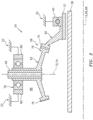
- the turbine engine 10 includes a fan section 18, a compressor section 19, a combustor section 20 and a turbine section 21.
- the compressor section 19 includes a low pressure compressor (LPC) section 19A and a high pressure compressor (HPC) section 19B.
- the turbine section 21 includes a high pressure turbine (HPT) section 21A and a low pressure turbine (LPT) section 21B.
- the shafts 36-38 are rotatably supported by a plurality of bearings 40; e.g., rolling element and/or thrust bearings.
- bearings 40 e.g., rolling element and/or thrust bearings.
- Each of these bearings 40 is connected to the engine housing 22 by at least one stationary structure such as, for example, an annular support strut.
- the propulsion of the bypass air may account for a majority of thrust generated by the turbine engine 10, e.g., more than seventy-five percent (75%) of engine thrust.
- the turbine engine 10 of the present disclosure is not limited to the foregoing exemplary thrust ratio or specific engine configuration.
- the turbine engine 10 of FIG. 1 also includes an accessory gearbox 50, one or more gearbox attachments 52 and a transmission system 54.
- the accessory gearbox 50 is mounted to the inner case 24. However, in alternative embodiments, the accessory gearbox 50 may be mounted elsewhere with the turbine engine 10; e.g., to the outer case 26.
- the accessory gearbox 50 is configured to transfer rotational energy (e.g., torque) between the transmission system 54 and the one or more gearbox attachments 52.
- An example of an accessory gearbox is disclosed in U.S. Patent No. 9,068,515 to Duong et al. , which is assigned to the assignee of the present disclosure.
- Examples of a gearbox attachment may include an air turbine starter, a deoiler, a hydraulic pump, an oil pump, an integrated drive generator, a permanent magnet alternator and a fuel pump module.
- a gearbox attachment may include an air turbine starter, a deoiler, a hydraulic pump, an oil pump, an integrated drive generator, a permanent magnet alternator and a fuel pump module.
- the present disclosure is not limited to including the foregoing exemplary types or configurations of the accessory gearbox 50 or the gearbox attachments 52.
- the transmission system 54 is configured to mechanically couple and thereby transfer rotational energy (e.g., torque) between a rotating assembly (or component) of the turbine engine 10 and the accessory gearbox 50.
- the transmission system 54 of FIG. 1 mechanically couples one of the spools of the turbine engine 10 (e.g., the high speed spool) with the accessory gearbox 50.
- This transmission system 54 includes the high speed shaft 38, a tower shaft 56 and a coupling assembly such as a geared system 58.
- the geared system 58 includes a first gear 60 and a second gear 62.
- the first gear 60 of FIG. 2 is configured as a bull gear such as, for example, a bevel bull gear.
- This first gear 60 is mounted to the high speed shaft 38, for example, by a spline interface / connection 86 (e.g., see FIG. 3 ).
- the first gear 60 has a first rotational axis 66, which is coaxial with a rotational axis 68 of the low speed shaft 37; e.g., the centerline 12.
- the first gear 60 includes a plurality of first gear teeth 70. These first gear teeth 70 are arranged in a circumferential array, which extends circumferentially around the first rotational axis 66.
- the second gear 62 of FIG. 2 is configured as a pinion gear such as, for example, a bevel pinion gear.
- This second gear 62 is mounted to the tower shaft 56, for example, by a spline interface.
- the second gear 62 has a second rotational axis 72, which is coaxial with a rotational axis 74 of the tower shaft 56.
- This second rotational axis 72 is arranged coincident with and is angularly offset from (e.g., perpendicular to) the first rotational axis 66 as well as the centerline 12.
- the second rotational axis 72 may be arranged coincident with and acutely or obtusely angled to the first rotational axis 66.
- the second gear 62 includes a plurality of second gear teeth 76. These second gear teeth 76 are arranged in a circumferential array, which extends circumferentially around the second rotational axis 72.
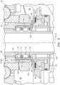
- the bearing 78 as well as the gear system 58 and other engine components are housed within a compartment 88; e.g., a bearing compartment.
- Fluid e.g., gas
- this compartment 88 may be at a relatively high pressure.
- Components subject to such a relatively high fluid pressure may require use of more robust materials and/or designs. Therefore, to isolate the relatively high pressure fluid within the compartment 88 from areas and components (e.g., low pressure seals for the gearbox 50) outside of the compartment 88, the turbine engine 10 is configured with a fluid (e.g., gas) seal assembly 90.
- a fluid e.g., gas
- the seal support assembly 94 mounts the seal element 96 to the stationary structure 92.
- the seal support assembly 94 is configured to bias (e.g., push) the seal element 96 axially towards the second gear 62 such that the seal element 96 axially engages (e.g., contacts) the second gear 62.
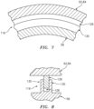
- the tubular base 82 of the second gear 62 extends axially along the rotational axis 72 to a distal annular end surface 98.
- a distal annular end surface 100 of the seal element 96 which is axially opposite and parallel with the end surface 98, is biased axially against the end surface 98 to form a sealed interface between the seal element 96 and the second gear 62.
- each of the apertures 104 is adapted to direct lubricant 106 flowing within an intra-component passage 108 into the compartment 88, where the lubricant 106 absorbs heat energy from the second gear 62 through conduction while passing through the apertures 104.
- the fluid permeable seal assembly 112 may include a seal ring 118 (e.g., an annular spiral retaining ring) seated in a groove 120 of the tower shaft 56.
- This groove 120 extends axially between a pair of circumferentially interrupted (e.g., splined or castellated) flanges 122, which flanges 122 project radially out from a tubular sidewall of the tower shaft 56.
- a controlled rate of lubricant 106 may flow through the interruptions 124 (e.g., slots) in the flanges 122 and, thus, flow axially across the seal assembly 112.
- the term "fluid impermeable” may be used to describe a seal assembly configured to substantially or completely prevent fluid leakage thereacross.
- the fluid impermeable seal assembly 116 may include a seal ring 126 (e.g., an annular spiral retaining ring) seated in another groove 128 of the tower shaft 56.
- This groove 128 extends axially between a pair of circumferentially uninterrupted flanges 130, which flanges 130 project radially out from the tubular sidewall of the tower shaft 56.
- the combination of the elements 126 and 130 may substantially (compared to the controlled leakage across the seal assembly) prevent or completely prevent lubricant 106 flow across the seal assembly 116.
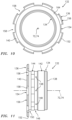
- the turbine engine 10 may include a replaceable engine component that provides an intermediate body between the seal element 96 and the second gear 62.
- the replaceable engine component is configured as a seal runner 132.
- the seal runner 132 of FIGS. 10 and 11 includes a tubular base 134 and an annular flange 136, which are formed together as a unitary monolithic full hoop body.
- the tubular base 134 extends axially along the rotational axis 72, 74 between axially opposed ends 138 and 140 of the seal runner 132.
- the tubular base 134 includes a threaded portion 142 and a circumferentially interrupted (e.g., castellated) ring portion 144.
- a first annulus 146 (e.g., an annular channel) is formed axially between the threaded portion 142 and the ring portion 144.
- This annulus 146 is fluidly coupled with one or more apertures 148 (e.g., lubricant passages), which extend through a tubular sidewall of the tubular base 134. These apertures 148 are arranged in a circumferential array about the rotational axis 72, 74.
- a second annulus 150 e.g., an annular channel is formed axially between the annular flange 136 and the ring portion 144.
- the annular flange 136 is located at (e.g., on, adjacent or proximate) the second end 140 of the seal runner 132.
- the annular flange 136 extends circumferentially about the rotational axis 72, 74.
- the annular flange 136 projects radially out from the tubular base 134 to a distal end 152.
- the annular flange 136 of FIGS. 10 and 11 includes a circumferentially uninterrupted inner portion 154 and a circumferentially interrupted outer portion 156 (e.g., a castellated, slotted outer peripheral portion).
- the inner portion 154 extends radially from the tubular base 134 to the outer portion 156.
- the outer portion 156 extends radially from the inner portion 154 to the distal end 152.
- the outer portion 156 is configured with one or more slots 158.
- Each of these slots 158 extends radially into the annular flange 136 from the distal end 152.
- Each of the slots 158 extends axially through the annular flange 136. This arrangement of slots 158 may be configured for mating with a tool to aid in the installation and/or removal of the seal runner 132 from the turbine engine 10.
- the seal element 96 is configured to axially engage (e.g., contact) a distal annular end surface 164 of the seal runner 132 and its inner portion 154 and annular flange 136 in a similar manner as described above with respect to the engagement between the components 62 and 96 (see FIG. 3 ).
- the seal runner 132 of FIG. 9 therefore is configured with the one or more apertures 148.
- the apertures 148 are operable to direct lubricant 106 flowing within the intra-component passage 108 into the compartment 88, where the lubricant 106 absorbs heat energy from the seal runner 132 through conduction while passing through the apertures 148 and along the axially and radially extending surfaces 166 and 168 of the seal runner 132.
- the intra-component passage 108 of FIG. 12 extends axially through the spline connection 86 between the second gear 62 and the tower shaft 56 and into the first annulus 110.
- the intra-component passage 108 then extends axially across the fluid permeable seal assembly 112 and into the second annulus 114.
- This second annulus 114 is fluidly coupled with and, thus, is adapted to feed lubricant 106 into one or more of the apertures 148.
- the lubricant 106 then passes sequentially through the first annulus 146 and slots in the ring portion 144 and into the second annulus 150.
- the distal end surface 98 of the second gear 62 in the embodiment of FIG. 9 may be circumferentially interrupted by one or more slots; e.g., a distal end of the second gear 62 may be castellated.
- the seal rings 118 and 126 of the seal assemblies 112 and 116 are configured to radially engage (e.g., contact) an inner surface 170 of the seal runner 132 rather than an inner surface of the second gear 62 as shown in FIG. 4 .
- the inner surface 170 of the seal runner 132 may be recessed radially outward from an inner lip 172 of the seal runner 132. With such a configuration, the lip 172 may function as a retainer for the tower shaft 56 during installation.
- the assemblies described above may be included in various turbine engines other than the one described above.
- the assemblies of FIGS. 3 and 9 may be included in a geared turbine engine where a gear train connects one or more shafts to one or more rotors in a fan section, a compressor section and/or any other engine section.
- the assemblies of FIGS. 3 and 9 may be included in a turbine engine configured without a gear train.
- the assemblies of FIGS. 3 and 9 may be included in a geared or non-geared turbine engine configured with a single spool, with two spools (e.g., see FIG. 1 ), or with more than two spools.
- the turbine engine may be configured as a turbofan engine, a turbojet engine, a propfan engine, a pusher fan engine or any other type of turbine engine. The present disclosure therefore is not limited to any particular types or configurations of turbine engines.
Landscapes
- Engineering & Computer Science (AREA)
- General Engineering & Computer Science (AREA)
- Mechanical Engineering (AREA)
- Sealing Using Fluids, Sealing Without Contact, And Removal Of Oil (AREA)
- Turbine Rotor Nozzle Sealing (AREA)
- Sealing Devices (AREA)
Applications Claiming Priority (2)
| Application Number | Priority Date | Filing Date | Title |
|---|---|---|---|
| US16/131,145 US10830078B2 (en) | 2018-09-14 | 2018-09-14 | Shaft seal assembly for a turbine engine |
| EP19185866.1A EP3623588B1 (de) | 2018-09-14 | 2019-07-11 | Wellendichtungsanordnung für einen turbinenmotor |
Related Parent Applications (2)
| Application Number | Title | Priority Date | Filing Date |
|---|---|---|---|
| EP19185866.1A Division EP3623588B1 (de) | 2018-09-14 | 2019-07-11 | Wellendichtungsanordnung für einen turbinenmotor |
| EP19185866.1A Division-Into EP3623588B1 (de) | 2018-09-14 | 2019-07-11 | Wellendichtungsanordnung für einen turbinenmotor |
Publications (2)
| Publication Number | Publication Date |
|---|---|
| EP4575191A2 true EP4575191A2 (de) | 2025-06-25 |
| EP4575191A3 EP4575191A3 (de) | 2025-08-06 |
Family
ID=67253826
Family Applications (2)
| Application Number | Title | Priority Date | Filing Date |
|---|---|---|---|
| EP25168384.3A Pending EP4575191A3 (de) | 2018-09-14 | 2019-07-11 | Wellendichtungsanordnung für einen turbinenmotor |
| EP19185866.1A Active EP3623588B1 (de) | 2018-09-14 | 2019-07-11 | Wellendichtungsanordnung für einen turbinenmotor |
Family Applications After (1)
| Application Number | Title | Priority Date | Filing Date |
|---|---|---|---|
| EP19185866.1A Active EP3623588B1 (de) | 2018-09-14 | 2019-07-11 | Wellendichtungsanordnung für einen turbinenmotor |
Country Status (2)
| Country | Link |
|---|---|
| US (1) | US10830078B2 (de) |
| EP (2) | EP4575191A3 (de) |
Families Citing this family (10)
| Publication number | Priority date | Publication date | Assignee | Title |
|---|---|---|---|---|
| US11053858B2 (en) * | 2019-02-07 | 2021-07-06 | Raytheon Technologies Corporation | Low leakage seal for tower shaft |
| FR3109801B1 (fr) * | 2020-05-04 | 2022-04-01 | Safran Aircraft Engines | Agencement pour turbomachine d’aeronef a lubrification amelioree, l’agencement comprenant un arbre couple en rotation a un element suiveur, par des cannelures |
| US11371374B2 (en) * | 2020-07-22 | 2022-06-28 | Raytheon Technologies Corporation | Seal runner flow damper |
| FR3115558B1 (fr) | 2020-10-27 | 2023-12-15 | Safran Aircraft Engines | Dispositif de pressurisation d’une enceinte aval de turbomachine et turbomachine correspondante. |
| EP4293199A3 (de) * | 2022-06-14 | 2024-02-28 | Hamilton Sundstrand Corporation | Dichtungsüberwachungssystem und verfahren zur überwachung einer dichtung |
| US12492663B2 (en) | 2022-08-12 | 2025-12-09 | Rtx Corporation | Aircraft propulsion system geartrain |
| US12188551B1 (en) | 2023-09-29 | 2025-01-07 | Rtx Corporation | Reduced clearance interface between a fluid device and a rotating structure for a geartrain |
| US12292107B2 (en) | 2023-09-29 | 2025-05-06 | Rtx Corporation | Fluid damper for turbine engine geartrain assembly |
| US12135076B1 (en) | 2023-09-29 | 2024-11-05 | Rtx Corporation | Fluid device(s) for supporting rotating structure(s) of a turbine engine |
| US12331683B2 (en) | 2023-09-29 | 2025-06-17 | Rtx Corporation | Bearing arrangement for turbine engine geartrain |
Citations (1)
| Publication number | Priority date | Publication date | Assignee | Title |
|---|---|---|---|---|
| US9068515B2 (en) | 2011-12-07 | 2015-06-30 | United Technologies Corporation | Accessory gearbox with tower shaft removal capability |
Family Cites Families (74)
| Publication number | Priority date | Publication date | Assignee | Title |
|---|---|---|---|---|
| US2990202A (en) * | 1958-09-18 | 1961-06-27 | United Aircraft Corp | Labyrinth face seal plate |
| NL130801C (de) * | 1961-02-10 | |||
| US3572727A (en) * | 1969-07-16 | 1971-03-30 | Sealol | Unloading gas barrier face seal |
| US3804424A (en) * | 1972-04-24 | 1974-04-16 | Crane Packing Co | Gap seal with thermal and pressure distortion compensation |
| DE2228081C3 (de) * | 1972-06-09 | 1975-11-27 | Klein, Schanzlin & Becker Ag, 6710 Frankenthal | Gleitringdichtung fur Medien wechselnder Temperatur |
| US3942387A (en) * | 1974-10-15 | 1976-03-09 | United Technologies Corporation | Replaceable freewheel unit for helicopters |
| GB1559879A (en) * | 1976-08-14 | 1980-01-30 | Rolls Royce | Bevel gearing |
| DE2861253D1 (en) * | 1978-12-15 | 1981-12-10 | Freudenberg Carl Fa | Sealing for a gap between a rotating shaft and a crank case bore against a mixture of fluid and gas |
| DE3003001A1 (de) * | 1980-01-29 | 1981-07-30 | Klöckner-Humboldt-Deutz AG, 5000 Köln | Vorrichtung zum gasdichten abschliessen von verbindungsstellen drehbeweglich gelagerter maschinenteile |
| JPS58170971A (ja) * | 1982-04-01 | 1983-10-07 | Eagle Ind Co Ltd | スタ−ンチユ−ブシ−ル |
| US4406459A (en) * | 1982-06-18 | 1983-09-27 | United Technologies Corporation | Oil weepage return for carbon seal plates |
| DE3231171C1 (de) * | 1982-08-21 | 1983-05-19 | M.A.N. Maschinenfabrik Augsburg-Nürnberg AG, 4200 Oberhausen | Sperrfluessigkeitsdichtung |
| US4406460A (en) * | 1982-11-01 | 1983-09-27 | United Technologies Corporation | Anti-weepage valve for rotating seals |
| US5052694A (en) * | 1986-07-08 | 1991-10-01 | Eg&G Sealol, Inc. | Hydrostatic face seal and bearing |
| US4687346A (en) * | 1986-09-02 | 1987-08-18 | United Technologies Corporation | Low profile bearing support structure |
| US4948151A (en) * | 1986-10-10 | 1990-08-14 | Atomic Energy Of Canada Limited | Rotary end face seal assembly |
| US4990054A (en) * | 1989-12-13 | 1991-02-05 | Westinghouse Electric Corp. | Device incorporating micro-porous membrane for venting gases from seal assembly of a reactor coolant pump |
| US5106105A (en) * | 1990-10-17 | 1992-04-21 | United States Department Of Energy | Rotary kiln seal |
| US5249924A (en) * | 1992-02-21 | 1993-10-05 | Southwest Aerospace Corporation | RAM air turbine |
| DE4209953A1 (de) * | 1992-03-27 | 1993-09-30 | Freudenberg Carl Fa | Dichtungsanordnung |
| EP0685048B1 (de) * | 1992-08-11 | 2000-01-19 | United Technologies Corporation | Dichtanordnung für rotierende maschinen |
| US5636848A (en) * | 1995-02-22 | 1997-06-10 | Alliedsignal Inc. | Oil seal for a high speed rotating shaft |
| US5622438A (en) * | 1995-07-12 | 1997-04-22 | United Technologies Corporation | Fire resistant bearing compartment cover |
| US5658127A (en) * | 1996-01-26 | 1997-08-19 | Sundstrand Corporation | Seal element cooling in high speed mechanical face seals |
| DE19745662A1 (de) * | 1997-10-17 | 1999-04-22 | Bitzer Kuehlmaschinenbau Gmbh | Kompressor |
| WO1999027281A1 (en) * | 1997-11-21 | 1999-06-03 | Nippon Pillar Packing Co., Ltd. | Static pressure noncontact gas seal |
| US6109617A (en) * | 1998-03-04 | 2000-08-29 | Power Packing Co., Inc. | Gas seal assembly and method of sealing |
| DE69822443T2 (de) * | 1998-06-26 | 2005-01-20 | Techspace Aero, Milmort | Turbomachinenvorrichtung mit einer Dichtung |
| US6196790B1 (en) * | 1998-12-17 | 2001-03-06 | United Technologies Corporation | Seal assembly for an intershaft seal in a gas turbine engine |
| US6132168A (en) * | 1998-12-23 | 2000-10-17 | United Technologies Corporation | Balancing a pressure drop across ring seals in gas turbine engines |
| US6996968B2 (en) * | 2003-12-17 | 2006-02-14 | United Technologies Corporation | Bifurcated oil scavenge system for a gas turbine engine |
| GB0414235D0 (en) * | 2004-06-25 | 2004-07-28 | Rolls Royce Plc | A lubrication arrangement |
| US8011883B2 (en) * | 2004-12-29 | 2011-09-06 | United Technologies Corporation | Gas turbine engine blade tip clearance apparatus and method |
| US7341426B2 (en) * | 2004-12-29 | 2008-03-11 | United Technologies Corporation | Gas turbine engine blade tip clearance apparatus and method |
| US7287711B2 (en) * | 2005-05-27 | 2007-10-30 | Hunter Industries, Inc. A Delaware Corporation | Adjustable arc rotor-type sprinkler with selectable uni-directional full circle nozzle rotation |
| US7648143B2 (en) * | 2005-10-18 | 2010-01-19 | United Technologies Corporation | Tandem dual element intershaft carbon seal |
| US20080148881A1 (en) * | 2006-12-21 | 2008-06-26 | Thomas Ory Moniz | Power take-off system and gas turbine engine assembly including same |
| US8167091B2 (en) * | 2007-03-28 | 2012-05-01 | Pratt & Whitney Canada Corp. | Oil scavenge system having churning damper for gas turbine engines |
| US8528697B2 (en) * | 2008-08-12 | 2013-09-10 | GM Global Technology Operations LLC | Differential lubricant temperature controller |
| US9004495B2 (en) * | 2008-09-15 | 2015-04-14 | Stein Seal Company | Segmented intershaft seal assembly |
| JP4958889B2 (ja) * | 2008-12-05 | 2012-06-20 | 川崎重工業株式会社 | 歯車列の潤滑装置 |
| US8167314B2 (en) * | 2009-03-31 | 2012-05-01 | United Technologies Corporation | Distortion resistant face seal counterface system |
| DE202009010047U1 (de) * | 2009-07-23 | 2010-12-23 | Gapi Technische Produkte Gmbh | Öldrehdurchführung |
| US8777229B2 (en) * | 2010-03-26 | 2014-07-15 | United Technologies Corporation | Liftoff carbon seal |
| FR2957982B1 (fr) * | 2010-03-29 | 2012-04-13 | Valeo Equip Electr Moteur | Palier avant de demarreur de moteur thermique a pignon sortant et demarreur a pignon sortant comportant un tel palier |
| US8657573B2 (en) * | 2010-04-13 | 2014-02-25 | Rolls-Royce Corporation | Circumferential sealing arrangement |
| GB201013844D0 (en) * | 2010-08-19 | 2010-09-29 | Rolls Royce Plc | Intershaft seal |
| US8747054B2 (en) * | 2011-01-24 | 2014-06-10 | United Technologies Corporation | Bearing system for gas turbine engine |
| US8919134B2 (en) * | 2011-01-26 | 2014-12-30 | United Technologies Corporation | Intershaft seal with support linkage |
| GB201111531D0 (en) * | 2011-07-06 | 2011-08-17 | Rolls Royce Plc | A sealing arrangement |
| GB2495092B (en) * | 2011-09-28 | 2014-01-01 | Rolls Royce Plc | Sealing arrangement |
| US9896968B2 (en) * | 2012-07-30 | 2018-02-20 | United Technologies Corporation | Forward compartment baffle arrangement for a geared turbofan engine |
| US9476321B2 (en) * | 2012-09-20 | 2016-10-25 | United Technologies Corporation | Turbomachine fluid delivery manifold and system |
| US9726031B2 (en) * | 2012-09-28 | 2017-08-08 | United Technologies Corporation | Piston ring coated carbon seal |
| US9631508B2 (en) * | 2013-06-13 | 2017-04-25 | Pratt & Whitney Canada Corp. | Internally cooled seal runner |
| US9376999B2 (en) * | 2013-08-22 | 2016-06-28 | Paul H. Sloan, Jr. | Engine starter inertia drive |
| EP3094826B1 (de) * | 2014-01-08 | 2022-04-06 | Raytheon Technologies Corporation | Geflanschte federführung für eine gleitringdichtungsanordnung eines gasturbinentriebwerks |
| EP3120065B1 (de) * | 2014-03-18 | 2018-01-31 | GE Avio S.r.l. | Ölübertragungsanordnung mit fluss eines schmieröls aus einem stehenden teil zu einem rotierenden teil, insbesondere für epizyklisches getriebe |
| US9714712B2 (en) * | 2014-08-15 | 2017-07-25 | Eaton Corporation | Hydrodynamic mating ring with integrated groove inlet pressure control |
| US9970526B1 (en) * | 2015-02-02 | 2018-05-15 | Hamilton Sundstrand Corporation | Ram air turbine lip seal sealing surface sleeve cap |
| US9732630B2 (en) * | 2015-03-27 | 2017-08-15 | United Technologies Corporation | Oil scoop and shaft with axially-oriented hole |
| US9915175B2 (en) * | 2015-07-15 | 2018-03-13 | United Technologies Corporation | Seal runner with controlled oil lubrication |
| US10563530B2 (en) * | 2015-10-12 | 2020-02-18 | General Electric Company | Intershaft seal with dual opposing carbon seal rings |
| US10197150B2 (en) * | 2015-11-23 | 2019-02-05 | United Technologies Corporation | Gear baffle configured with lubricant outlet passage |
| US10221937B2 (en) * | 2016-04-05 | 2019-03-05 | United Technologies Corporation | Slotted oil baffle for gears |
| WO2016179608A2 (en) * | 2016-04-29 | 2016-11-10 | Stein Seal Company | Intershaft seal with asymmetric sealing ring |
| US10598035B2 (en) * | 2016-05-27 | 2020-03-24 | General Electric Company | Intershaft sealing systems for gas turbine engines and methods for assembling the same |
| US10066733B2 (en) * | 2016-07-19 | 2018-09-04 | United Technologies Corporation | Oil direction control baffle |
| US20180045316A1 (en) * | 2016-08-09 | 2018-02-15 | United Technologies Corporation | Hydrodynamic seal seat cooling features |
| US10364880B2 (en) * | 2017-01-05 | 2019-07-30 | United Technologies Corporation | Oil quieting direction control baffle |
| US10557362B2 (en) * | 2017-03-30 | 2020-02-11 | General Electric Company | Method and system for a pressure activated cap seal |
| US10598020B2 (en) * | 2018-01-05 | 2020-03-24 | United Technologies Corporation | Spanner nut centering feature |
| US20190226585A1 (en) * | 2018-01-25 | 2019-07-25 | General Electric Company | Hydrodynamic Intershaft Piston Ring Seal |
| US11708909B2 (en) * | 2018-04-27 | 2023-07-25 | Hamilton Sundstrand Corporation | Carbon seal |
-
2018
- 2018-09-14 US US16/131,145 patent/US10830078B2/en active Active
-
2019
- 2019-07-11 EP EP25168384.3A patent/EP4575191A3/de active Pending
- 2019-07-11 EP EP19185866.1A patent/EP3623588B1/de active Active
Patent Citations (1)
| Publication number | Priority date | Publication date | Assignee | Title |
|---|---|---|---|---|
| US9068515B2 (en) | 2011-12-07 | 2015-06-30 | United Technologies Corporation | Accessory gearbox with tower shaft removal capability |
Also Published As
| Publication number | Publication date |
|---|---|
| EP4575191A3 (de) | 2025-08-06 |
| EP3623588B1 (de) | 2025-05-14 |
| EP3623588A1 (de) | 2020-03-18 |
| US20200088053A1 (en) | 2020-03-19 |
| US10830078B2 (en) | 2020-11-10 |
Similar Documents
| Publication | Publication Date | Title |
|---|---|---|
| EP3623588B1 (de) | Wellendichtungsanordnung für einen turbinenmotor | |
| US10961860B2 (en) | Non-contact seal with removal features | |
| US11454320B2 (en) | Porous seal element with internal fluid passage | |
| EP4234989B1 (de) | Gleitende fluidkupplungsvorrichtung | |
| US10570776B2 (en) | Nozzle for delivering fluid to a component | |
| US20200256213A1 (en) | Fluid transfer assembly for rotational equipment | |
| EP3808943B1 (de) | Flüssigkeitsgekühlte dichtungsleiste für eine gleitringdichtungsanordnung | |
| US11371441B2 (en) | Translating fluid delivery device | |
| US11814975B2 (en) | Feed circuit with slot(s) at interface between journal bearing and rotor | |
| EP3904732B1 (de) | Rotationsgerätdichtungselement mit innerem fluidkanal | |
| EP3904644B1 (de) | Flüssigkeitsabgabesystem für rotationsgeräte | |
| US11131388B2 (en) | Seal assembly seal land with a gas flow passage | |
| EP4166774B1 (de) | Doppelkeilkupplung für einen turbinenmotor | |
| EP4286654A1 (de) | Verbindung zwischen gasturbinenmotorkomponenten mit verbundenen befestigungselementen |
Legal Events
| Date | Code | Title | Description |
|---|---|---|---|
| PUAI | Public reference made under article 153(3) epc to a published international application that has entered the european phase |
Free format text: ORIGINAL CODE: 0009012 |
|
| STAA | Information on the status of an ep patent application or granted ep patent |
Free format text: STATUS: THE APPLICATION HAS BEEN PUBLISHED |
|
| AC | Divisional application: reference to earlier application |
Ref document number: 3623588 Country of ref document: EP Kind code of ref document: P |
|
| AK | Designated contracting states |
Kind code of ref document: A2 Designated state(s): AL AT BE BG CH CY CZ DE DK EE ES FI FR GB GR HR HU IE IS IT LI LT LU LV MC MK MT NL NO PL PT RO RS SE SI SK SM TR |
|
| PUAL | Search report despatched |
Free format text: ORIGINAL CODE: 0009013 |
|
| AK | Designated contracting states |
Kind code of ref document: A3 Designated state(s): AL AT BE BG CH CY CZ DE DK EE ES FI FR GB GR HR HU IE IS IT LI LT LU LV MC MK MT NL NO PL PT RO RS SE SI SK SM TR |
|
| RIC1 | Information provided on ipc code assigned before grant |
Ipc: F01D 25/18 20060101AFI20250630BHEP |
|
| STAA | Information on the status of an ep patent application or granted ep patent |
Free format text: STATUS: REQUEST FOR EXAMINATION WAS MADE |