EP3904644B1 - Flüssigkeitsabgabesystem für rotationsgeräte - Google Patents
Flüssigkeitsabgabesystem für rotationsgeräte Download PDFInfo
- Publication number
- EP3904644B1 EP3904644B1 EP21170798.9A EP21170798A EP3904644B1 EP 3904644 B1 EP3904644 B1 EP 3904644B1 EP 21170798 A EP21170798 A EP 21170798A EP 3904644 B1 EP3904644 B1 EP 3904644B1
- Authority
- EP
- European Patent Office
- Prior art keywords
- assembly
- guide rail
- seal
- component
- static structure
- Prior art date
- Legal status (The legal status is an assumption and is not a legal conclusion. Google has not performed a legal analysis and makes no representation as to the accuracy of the status listed.)
- Active
Links
Images

Classifications
-
- F—MECHANICAL ENGINEERING; LIGHTING; HEATING; WEAPONS; BLASTING
- F02—COMBUSTION ENGINES; HOT-GAS OR COMBUSTION-PRODUCT ENGINE PLANTS
- F02C—GAS-TURBINE PLANTS; AIR INTAKES FOR JET-PROPULSION PLANTS; CONTROLLING FUEL SUPPLY IN AIR-BREATHING JET-PROPULSION PLANTS
- F02C7/00—Features, components parts, details or accessories, not provided for in, or of interest apart form groups F02C1/00 - F02C6/00; Air intakes for jet-propulsion plants
- F02C7/22—Fuel supply systems
- F02C7/222—Fuel flow conduits, e.g. manifolds
-
- F—MECHANICAL ENGINEERING; LIGHTING; HEATING; WEAPONS; BLASTING
- F01—MACHINES OR ENGINES IN GENERAL; ENGINE PLANTS IN GENERAL; STEAM ENGINES
- F01D—NON-POSITIVE DISPLACEMENT MACHINES OR ENGINES, e.g. STEAM TURBINES
- F01D25/00—Component parts, details, or accessories, not provided for in, or of interest apart from, other groups
- F01D25/08—Cooling; Heating; Heat-insulation
- F01D25/12—Cooling
- F01D25/125—Cooling of bearings
-
- B—PERFORMING OPERATIONS; TRANSPORTING
- B05—SPRAYING OR ATOMISING IN GENERAL; APPLYING FLUENT MATERIALS TO SURFACES, IN GENERAL
- B05B—SPRAYING APPARATUS; ATOMISING APPARATUS; NOZZLES
- B05B15/00—Details of spraying plant or spraying apparatus not otherwise provided for; Accessories
- B05B15/60—Arrangements for mounting, supporting or holding spraying apparatus
- B05B15/65—Mounting arrangements for fluid connection of the spraying apparatus or its outlets to flow conduits
-
- F—MECHANICAL ENGINEERING; LIGHTING; HEATING; WEAPONS; BLASTING
- F01—MACHINES OR ENGINES IN GENERAL; ENGINE PLANTS IN GENERAL; STEAM ENGINES
- F01D—NON-POSITIVE DISPLACEMENT MACHINES OR ENGINES, e.g. STEAM TURBINES
- F01D11/00—Preventing or minimising internal leakage of working-fluid, e.g. between stages
- F01D11/003—Preventing or minimising internal leakage of working-fluid, e.g. between stages by packing rings; Mechanical seals
-
- F—MECHANICAL ENGINEERING; LIGHTING; HEATING; WEAPONS; BLASTING
- F01—MACHINES OR ENGINES IN GENERAL; ENGINE PLANTS IN GENERAL; STEAM ENGINES
- F01D—NON-POSITIVE DISPLACEMENT MACHINES OR ENGINES, e.g. STEAM TURBINES
- F01D25/00—Component parts, details, or accessories, not provided for in, or of interest apart from, other groups
- F01D25/18—Lubricating arrangements
- F01D25/183—Sealing means
-
- F—MECHANICAL ENGINEERING; LIGHTING; HEATING; WEAPONS; BLASTING
- F16—ENGINEERING ELEMENTS AND UNITS; GENERAL MEASURES FOR PRODUCING AND MAINTAINING EFFECTIVE FUNCTIONING OF MACHINES OR INSTALLATIONS; THERMAL INSULATION IN GENERAL
- F16C—SHAFTS; FLEXIBLE SHAFTS; ELEMENTS OR CRANKSHAFT MECHANISMS; ROTARY BODIES OTHER THAN GEARING ELEMENTS; BEARINGS
- F16C19/00—Bearings with rolling contact, for exclusively rotary movement
- F16C19/02—Bearings with rolling contact, for exclusively rotary movement with bearing balls essentially of the same size in one or more circular rows
- F16C19/04—Bearings with rolling contact, for exclusively rotary movement with bearing balls essentially of the same size in one or more circular rows for radial load mainly
- F16C19/06—Bearings with rolling contact, for exclusively rotary movement with bearing balls essentially of the same size in one or more circular rows for radial load mainly with a single row or balls
-
- F—MECHANICAL ENGINEERING; LIGHTING; HEATING; WEAPONS; BLASTING
- F16—ENGINEERING ELEMENTS AND UNITS; GENERAL MEASURES FOR PRODUCING AND MAINTAINING EFFECTIVE FUNCTIONING OF MACHINES OR INSTALLATIONS; THERMAL INSULATION IN GENERAL
- F16C—SHAFTS; FLEXIBLE SHAFTS; ELEMENTS OR CRANKSHAFT MECHANISMS; ROTARY BODIES OTHER THAN GEARING ELEMENTS; BEARINGS
- F16C33/00—Parts of bearings; Special methods for making bearings or parts thereof
- F16C33/30—Parts of ball or roller bearings
- F16C33/66—Special parts or details in view of lubrication
- F16C33/6637—Special parts or details in view of lubrication with liquid lubricant
- F16C33/6659—Details of supply of the liquid to the bearing, e.g. passages or nozzles
-
- F—MECHANICAL ENGINEERING; LIGHTING; HEATING; WEAPONS; BLASTING
- F16—ENGINEERING ELEMENTS AND UNITS; GENERAL MEASURES FOR PRODUCING AND MAINTAINING EFFECTIVE FUNCTIONING OF MACHINES OR INSTALLATIONS; THERMAL INSULATION IN GENERAL
- F16C—SHAFTS; FLEXIBLE SHAFTS; ELEMENTS OR CRANKSHAFT MECHANISMS; ROTARY BODIES OTHER THAN GEARING ELEMENTS; BEARINGS
- F16C33/00—Parts of bearings; Special methods for making bearings or parts thereof
- F16C33/72—Sealings
- F16C33/76—Sealings of ball or roller bearings
-
- F—MECHANICAL ENGINEERING; LIGHTING; HEATING; WEAPONS; BLASTING
- F16—ENGINEERING ELEMENTS AND UNITS; GENERAL MEASURES FOR PRODUCING AND MAINTAINING EFFECTIVE FUNCTIONING OF MACHINES OR INSTALLATIONS; THERMAL INSULATION IN GENERAL
- F16C—SHAFTS; FLEXIBLE SHAFTS; ELEMENTS OR CRANKSHAFT MECHANISMS; ROTARY BODIES OTHER THAN GEARING ELEMENTS; BEARINGS
- F16C37/00—Cooling of bearings
- F16C37/007—Cooling of bearings of rolling bearings
-
- F—MECHANICAL ENGINEERING; LIGHTING; HEATING; WEAPONS; BLASTING
- F16—ENGINEERING ELEMENTS AND UNITS; GENERAL MEASURES FOR PRODUCING AND MAINTAINING EFFECTIVE FUNCTIONING OF MACHINES OR INSTALLATIONS; THERMAL INSULATION IN GENERAL
- F16J—PISTONS; CYLINDERS; SEALINGS
- F16J15/00—Sealings
- F16J15/16—Sealings between relatively-moving surfaces
- F16J15/34—Sealings between relatively-moving surfaces with slip-ring pressed against a more or less radial face on one member
- F16J15/3404—Sealings between relatively-moving surfaces with slip-ring pressed against a more or less radial face on one member and characterised by parts or details relating to lubrication, cooling or venting of the seal
-
- F—MECHANICAL ENGINEERING; LIGHTING; HEATING; WEAPONS; BLASTING
- F16—ENGINEERING ELEMENTS AND UNITS; GENERAL MEASURES FOR PRODUCING AND MAINTAINING EFFECTIVE FUNCTIONING OF MACHINES OR INSTALLATIONS; THERMAL INSULATION IN GENERAL
- F16J—PISTONS; CYLINDERS; SEALINGS
- F16J15/00—Sealings
- F16J15/16—Sealings between relatively-moving surfaces
- F16J15/34—Sealings between relatively-moving surfaces with slip-ring pressed against a more or less radial face on one member
- F16J15/3436—Pressing means
- F16J15/3452—Pressing means the pressing force resulting from the action of a spring
-
- F—MECHANICAL ENGINEERING; LIGHTING; HEATING; WEAPONS; BLASTING
- F16—ENGINEERING ELEMENTS AND UNITS; GENERAL MEASURES FOR PRODUCING AND MAINTAINING EFFECTIVE FUNCTIONING OF MACHINES OR INSTALLATIONS; THERMAL INSULATION IN GENERAL
- F16J—PISTONS; CYLINDERS; SEALINGS
- F16J15/00—Sealings
- F16J15/16—Sealings between relatively-moving surfaces
- F16J15/34—Sealings between relatively-moving surfaces with slip-ring pressed against a more or less radial face on one member
- F16J15/3464—Mounting of the seal
-
- F—MECHANICAL ENGINEERING; LIGHTING; HEATING; WEAPONS; BLASTING
- F16—ENGINEERING ELEMENTS AND UNITS; GENERAL MEASURES FOR PRODUCING AND MAINTAINING EFFECTIVE FUNCTIONING OF MACHINES OR INSTALLATIONS; THERMAL INSULATION IN GENERAL
- F16N—LUBRICATING
- F16N7/00—Arrangements for supplying oil or unspecified lubricant from a stationary reservoir or the equivalent in or on the machine or member to be lubricated
- F16N7/30—Arrangements for supplying oil or unspecified lubricant from a stationary reservoir or the equivalent in or on the machine or member to be lubricated the oil being fed or carried along by another fluid
- F16N7/32—Mist lubrication
- F16N7/34—Atomising devices for oil
-
- F—MECHANICAL ENGINEERING; LIGHTING; HEATING; WEAPONS; BLASTING
- F23—COMBUSTION APPARATUS; COMBUSTION PROCESSES
- F23R—GENERATING COMBUSTION PRODUCTS OF HIGH PRESSURE OR HIGH VELOCITY, e.g. GAS-TURBINE COMBUSTION CHAMBERS
- F23R3/00—Continuous combustion chambers using liquid or gaseous fuel
- F23R3/28—Continuous combustion chambers using liquid or gaseous fuel characterised by the fuel supply
-
- F—MECHANICAL ENGINEERING; LIGHTING; HEATING; WEAPONS; BLASTING
- F01—MACHINES OR ENGINES IN GENERAL; ENGINE PLANTS IN GENERAL; STEAM ENGINES
- F01M—LUBRICATING OF MACHINES OR ENGINES IN GENERAL; LUBRICATING INTERNAL COMBUSTION ENGINES; CRANKCASE VENTILATING
- F01M1/00—Pressure lubrication
- F01M1/08—Lubricating systems characterised by the provision therein of lubricant jetting means
-
- F—MECHANICAL ENGINEERING; LIGHTING; HEATING; WEAPONS; BLASTING
- F05—INDEXING SCHEMES RELATING TO ENGINES OR PUMPS IN VARIOUS SUBCLASSES OF CLASSES F01-F04
- F05D—INDEXING SCHEME FOR ASPECTS RELATING TO NON-POSITIVE-DISPLACEMENT MACHINES OR ENGINES, GAS-TURBINES OR JET-PROPULSION PLANTS
- F05D2250/00—Geometry
- F05D2250/30—Arrangement of components
- F05D2250/31—Arrangement of components according to the direction of their main axis or their axis of rotation
- F05D2250/314—Arrangement of components according to the direction of their main axis or their axis of rotation the axes being inclined in relation to each other
-
- F—MECHANICAL ENGINEERING; LIGHTING; HEATING; WEAPONS; BLASTING
- F05—INDEXING SCHEMES RELATING TO ENGINES OR PUMPS IN VARIOUS SUBCLASSES OF CLASSES F01-F04
- F05D—INDEXING SCHEME FOR ASPECTS RELATING TO NON-POSITIVE-DISPLACEMENT MACHINES OR ENGINES, GAS-TURBINES OR JET-PROPULSION PLANTS
- F05D2260/00—Function
- F05D2260/30—Retaining components in desired mutual position
- F05D2260/38—Retaining components in desired mutual position by a spring, i.e. spring loaded or biased towards a certain position
-
- F—MECHANICAL ENGINEERING; LIGHTING; HEATING; WEAPONS; BLASTING
- F16—ENGINEERING ELEMENTS AND UNITS; GENERAL MEASURES FOR PRODUCING AND MAINTAINING EFFECTIVE FUNCTIONING OF MACHINES OR INSTALLATIONS; THERMAL INSULATION IN GENERAL
- F16C—SHAFTS; FLEXIBLE SHAFTS; ELEMENTS OR CRANKSHAFT MECHANISMS; ROTARY BODIES OTHER THAN GEARING ELEMENTS; BEARINGS
- F16C17/00—Sliding-contact bearings for exclusively rotary movement
- F16C17/02—Sliding-contact bearings for exclusively rotary movement for radial load only
-
- F—MECHANICAL ENGINEERING; LIGHTING; HEATING; WEAPONS; BLASTING
- F16—ENGINEERING ELEMENTS AND UNITS; GENERAL MEASURES FOR PRODUCING AND MAINTAINING EFFECTIVE FUNCTIONING OF MACHINES OR INSTALLATIONS; THERMAL INSULATION IN GENERAL
- F16C—SHAFTS; FLEXIBLE SHAFTS; ELEMENTS OR CRANKSHAFT MECHANISMS; ROTARY BODIES OTHER THAN GEARING ELEMENTS; BEARINGS
- F16C19/00—Bearings with rolling contact, for exclusively rotary movement
- F16C19/02—Bearings with rolling contact, for exclusively rotary movement with bearing balls essentially of the same size in one or more circular rows
-
- F—MECHANICAL ENGINEERING; LIGHTING; HEATING; WEAPONS; BLASTING
- F16—ENGINEERING ELEMENTS AND UNITS; GENERAL MEASURES FOR PRODUCING AND MAINTAINING EFFECTIVE FUNCTIONING OF MACHINES OR INSTALLATIONS; THERMAL INSULATION IN GENERAL
- F16C—SHAFTS; FLEXIBLE SHAFTS; ELEMENTS OR CRANKSHAFT MECHANISMS; ROTARY BODIES OTHER THAN GEARING ELEMENTS; BEARINGS
- F16C2360/00—Engines or pumps
- F16C2360/23—Gas turbine engines
-
- F—MECHANICAL ENGINEERING; LIGHTING; HEATING; WEAPONS; BLASTING
- F16—ENGINEERING ELEMENTS AND UNITS; GENERAL MEASURES FOR PRODUCING AND MAINTAINING EFFECTIVE FUNCTIONING OF MACHINES OR INSTALLATIONS; THERMAL INSULATION IN GENERAL
- F16C—SHAFTS; FLEXIBLE SHAFTS; ELEMENTS OR CRANKSHAFT MECHANISMS; ROTARY BODIES OTHER THAN GEARING ELEMENTS; BEARINGS
- F16C2360/00—Engines or pumps
- F16C2360/31—Wind motors
-
- F—MECHANICAL ENGINEERING; LIGHTING; HEATING; WEAPONS; BLASTING
- F16—ENGINEERING ELEMENTS AND UNITS; GENERAL MEASURES FOR PRODUCING AND MAINTAINING EFFECTIVE FUNCTIONING OF MACHINES OR INSTALLATIONS; THERMAL INSULATION IN GENERAL
- F16N—LUBRICATING
- F16N2210/00—Applications
- F16N2210/02—Turbines
-
- F—MECHANICAL ENGINEERING; LIGHTING; HEATING; WEAPONS; BLASTING
- F16—ENGINEERING ELEMENTS AND UNITS; GENERAL MEASURES FOR PRODUCING AND MAINTAINING EFFECTIVE FUNCTIONING OF MACHINES OR INSTALLATIONS; THERMAL INSULATION IN GENERAL
- F16N—LUBRICATING
- F16N2210/00—Applications
- F16N2210/14—Bearings
-
- Y—GENERAL TAGGING OF NEW TECHNOLOGICAL DEVELOPMENTS; GENERAL TAGGING OF CROSS-SECTIONAL TECHNOLOGIES SPANNING OVER SEVERAL SECTIONS OF THE IPC; TECHNICAL SUBJECTS COVERED BY FORMER USPC CROSS-REFERENCE ART COLLECTIONS [XRACs] AND DIGESTS
- Y02—TECHNOLOGIES OR APPLICATIONS FOR MITIGATION OR ADAPTATION AGAINST CLIMATE CHANGE
- Y02T—CLIMATE CHANGE MITIGATION TECHNOLOGIES RELATED TO TRANSPORTATION
- Y02T50/00—Aeronautics or air transport
- Y02T50/60—Efficient propulsion technologies, e.g. for aircraft
Definitions
- This disclosure (invention) relates generally to rotational equipment and, more particularly, to fluid delivery to a component within a piece of rotational equipment.
- Rotational equipment such as a gas turbine engine may include a fluid delivery system for delivering lubricant and/or coolant to one or more components within the gas turbine engine.
- a fluid delivery system for delivering lubricant and/or coolant to one or more components within the gas turbine engine.
- US 2018/347389 A1 discloses features of the preamble of claim 1. Similar assemblies are also known from US 3 025 115 A , US 2016/348522 A1 and US 2020/080478 A1 .
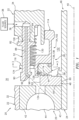
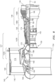
- FIG. 1 is a partial side sectional illustration of an assembly 20 for a piece of rotational equipment.
- the piece of rotational equipment may be configured as a gas turbine engine for an aircraft propulsion system such as, but not limited to, a geared or direct-drive turbofan gas turbine engine.
- the assembly 20 of the present disclosure is not limited to such an aircraft application nor a gas turbine engine application.
- the assembly 20, for example, may alternatively be configured with rotational equipment such as an industrial gas turbine engine, a wind turbine, a water turbine or any other apparatus which includes a seal assembly for sealing a gap between a rotating component and a static / fixed component.
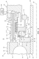
- the assembly 20 of FIG. 1 includes a static structure 22, a rotating structure 24 and at least one bearing 26 for rotatably supporting the rotating structure 24 relative to the static structure 22.
- the assembly 20 of FIG. 1 also includes a seal assembly 28.
- the static structure 22 is configured as a stationary part of the rotational equipment.
- the static structure 22 of FIG. 1 is configured to at least partially form an internal bearing compartment 30 for housing at least the bearing 26.
- This static structure 22 includes a bearing support 32 such as, but not limited to, a strut.
- the static structure 22 also includes a seal assembly support 34; e.g., an annular wall.
- the seal assembly support 34 of FIG. 1 is configured with an internal static structure fluid passage 36 which extends within the static structure 22 and, more particularly, the seal assembly support 34.
- the static structure fluid passage 36 is configured to receive fluid (e.g., lubricant, coolant, etc.) from a fluid source 38 such as, but not limited to, a reservoir, pump, etc.
- the rotating structure 24 is rotatable about an axial centerline 40, which centerline 40 may be an axial centerline and/or a rotational axis of the rotational equipment.
- the rotating structure 24 of FIG. 1 is configured as a tubular shaft. However, in other embodiments, the rotating structure 24 may be configured as another component (e.g., a sleeve) mounted to and rotatable with a shaft of the rotational equipment, or any other rotor within the rotational equipment.
- the rotating structure 24 of FIG. 1 extends axially along the axial centerline 40 through (or partially into or within) the static structure 22.
- the static structure 22 of FIG. 1 thereby extends circumferentially about (e.g., completely around) the axial centerline 40 and the rotating structure 24.
- the bearing 26 may be configured as a roller element bearing.
- the bearing 26 of FIG. 1 for example, includes an annular outer race 42, an annular inner race 43 and a plurality of bearing elements 44; e.g., cylindrical or spherical elements.
- the outer race 42 circumscribes the inner race 43 and the bearing elements 44.
- the outer race 42 is mounted to the static structure 22 and, more particularly, the bearing support 32.
- the inner race 43 circumscribes and is mounted to the rotating structure 24.
- the bearing elements 44 are arranged in an annular array about the axial centerline 40, which array is radially between and engaged with the outer race 42 and the inner race 43.
- the present disclosure is not limited to the foregoing exemplary bearing configuration.
- the bearing 26 may alternatively be configured as a journal bearing or any other type of bearing utilized in the rotational equipment.
- the seal assembly 28 is configured to seal an annular gap between a rotating assembly 46 and the static structure 22, which rotating assembly 46 includes at least the rotating structure 24.
- the seal assembly 28 of FIG. 1 is configured to seal the gap which extends (e.g., radially and/or axially) between the static structure 22 and the rotating structure 24.
- the seal assembly 28 may seal a gap extending between the static structure 22 and another rotating component mounted to and/or rotatable with the rotating structure 24.
- the seal assembly 28 of FIG. 1 includes an annular seal land 48 and an annular seal element 50; e.g., a carbon seal element.
- the seal assembly 28 of FIG. 1 also includes one or more guide rails 52 and a seal support assembly 54.
- the seal land 48 is configured with a full hoop body that extends circumferentially about the axial centerline 40.
- the seal land 48 extends axially along the axial centerline 40 between an axial first end 56 and an axial second end 58.
- the seal land 48 extends radially between a radial inner side 60 and a radial outer side 62.
- the seal land 48 includes an annular, radially extending seal land surface 64 located at (e.g., on, adjacent or proximate) the axial second end 58.
- This seal land surface 64 may be an uninterrupted surface.
- the seal land surface 64 may be a flat planar surface configured without circumferential and/or radial interruptions such as, but not limited to, channels, slots and apertures.
- the seal land surface 64 may be circumferentially and/or radially interrupted by one or more channels, slots, apertures and/or other types of surface interruptions.
- the seal element 50 is configured with a full hoop body that extends circumferentially about the axial centerline 40.
- This full hoop body may be a single unitary body; e.g., a monolithic body.
- the full hoop body may be a segmented body; e.g., the seal element 50 may be configured from an array of arcuate seal element segments.
- the seal element 50 extends axially along the axial centerline 40 between an axial first end 66 and an axial second end 68.
- the seal element 50 extends radially between a radial inner side 70 and a radial outer side 72.
- the seal element 50 includes an annular, radially extending seal element surface 74 located at (e.g., on, adjacent or proximate) the axial first end 66.
- This seal element surface 74 may be an uninterrupted surface.
- the seal element surface 74 may be a flat planar surface configured without circumferential and/or radial interruptions such as, but not limited to, channels, slots and apertures.
- the seal element surface 74 may be circumferentially and/or radially interrupted by one or more channels, slots, apertures and/or other types of surface interruptions.
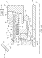
- each of the guide rails 52 are arranged circumferentially about the axial centerline 40 in an annular array.
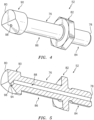
- each of the guide rails 52 may be configured as or otherwise include a guide pin.
- each guide rail 52 of FIG. 4 may have, but is not limited to, a generally cylindrical body 76 that extends axially between an axial first end 78 and an axial second end 80.
- a generally annular flange 82 may project out from and circumscribes the body 76.
- This flange 82 may be configured with a polygonal (e.g., hexagonal) peripheral cross-sectional geometry adapted for mating with an installation tool such as, but not limited to, a wrench or a socket.
- An axial first portion 84 of the body 76, axially between the axial first end 78 and the flange 82, may be configured with threads; e.g., the portion is a threaded portion.
- An axial second portion 86 of the body 76, axially between the axial second end 80 and the flange 82, may be configured with a smooth cylindrical surface.
- the guide rails 52 is each respectively configured with an internal guide rail fluid passage 88 (e.g., a pin fluid passage) and a fluid delivery nozzle 90.
- the guide rail fluid passage 88 includes / is formed by a (e.g., single) passageway through the guide rail 52.
- This passageway includes / is formed by a bore. This bore extends along a centerline 92 of the guide rail fluid passage 88 partially into the guide rail 52 from the axial first end 78 to the nozzle 90.
- the nozzle 90 is disposed at the axial second end 80.
- the nozzle 90 is configured with an internal nozzle fluid passage 94.
- the nozzle fluid passage 94 includes / is formed by a (e.g., single) passageway through the nozzle 90.
- This passageway includes / is formed by a bore. This bore extends along a nozzle orifice centerline 96 from the guide rail fluid passage 88 to an orifice 98 of the nozzle 90.
- the nozzle fluid passage 94 thereby extends between and fluidly couples the guide rail fluid passage 88 to the nozzle orifice 98.
- the nozzle orifice centerline 96 is angularly offset from the guide rail fluid passage centerline 92 by an included angle 100; e.g., an obtuse angle or an acute angle.
- the centerlines 92 and 96 may be angularly offset by between one hundred and ten degrees (110°) and one hundred and sixty degrees (160°).
- the present disclosure is not limited to such exemplary angles.
- the angle 100 may be less than one hundred and ten degrees (110°) or greater than one hundred and sixty degrees (160°).
- the respective guide rail 52 may be configured with more than one nozzle fluid passage 94 and/or nozzle orifice 98.
- the seal support assembly 54 is configured to translate axially along the guide rails 52.
- the seal support assembly 54 is also configured to support the seal element 50.
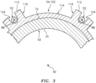
- the seal support assembly 54 of FIG. 1 for example, is configured as or otherwise includes a seal carrier 102.
- the seal carrier 102 is configured with a full hoop body that extends circumferentially about the axial centerline 40; see also FIG. 3 .
- the seal carrier 102 extends axially along the axial centerline 40 between an axial first end 104 and an axial second end 108.
- the seal carrier 102 extends radially, relative to the axial centerline 40, between a radial inner side 110 and a radial outer side 112.
- the seal carrier 102 of FIG. 7 includes a tubular carrier base 114 and one or more carrier flanges 116; see also FIG. 3 .
- the base 114 is configured with an annular recess / notch 118.
- This recess 118 extends axially partially into the base 114 from the axial first end 104 to an (e.g., annular) axial end surface 120.
- the recess 118 extends radially partially into the base 114 from the radial inner side 110 to a (e.g., tubular) radial end surface 122.
- the recess 118 forms a receptacle for the seal element 50 as described below in further detail.
- each flange 116 is arranged circumferentially about the base 114.
- Each flange 116 includes a slot 124.
- the seal land 48 is arranged with the rotating structure 24 in such a manner so as to be rotatable with the rotating structure 24 about the axial centerline 40.
- the seal land 48 of FIG. 1 for example, circumscribes and is fixedly mounted to the rotating structure 24; e.g., clamped between the inner race 43 and a shoulder on the rotating structure 24.
- each guide rail 52 is fixedly mounted to the static structure 22.
- the threaded portion 84 of each guide rail 52 may be screwed into a corresponding tapped hole 126 in the static structure 22.
- Each guide rail 52 is thereby connected to the static structure 22 by a threaded interface.
- each guide rail 52 may also or alternatively be connected to the static structure 22 through another type of interface connection; e.g., staking, riveting, press fitting, bolting, etc.
- the seal element 50 is seated in the receptacle of the seal carrier 102.
- a split ring 128 and/or another device secures the seal element 50 within the receptacle such that the seal element 50 is fixedly mounted to the seal carrier 102.
- the seal element 50 may also or alternatively be mounted to the seal carrier 102 using other fastening and/or bonding techniques.
- the seal carrier 102 is mated with the guide rails 52.
- each of the guide rails 52 projects through a respective flange slot 124; see also FIG. 3 .
- One or more spring elements 130 may be arranged between the static structure 22 and the seal carrier 102. These spring elements 130 are configured to bias the seal carrier 102 and, thus, the seal element 50 away from the static structure 22 and towards the seal land 48. In particular, the spring elements 130 cause the surfaces 64 and 74 to axially sealingly engage (e.g., contact) one another.
- seal element 50 sealingly engages the seal land 48.
- a combination of at least the seal element 50 and the seal support assembly 54 seal a gap between the seal land 48 and the static structure 22 and thereby fluidly divide (e.g., separate, isolate) the bearing compartment 30 from another plenum 132.
- each static structure fluid passage 36 supplies fluid (e.g., lubricant, coolant, oil, etc.) to a respective one of the guide rail fluid passages 88.
- Each guide rail fluid passage 88 supplies this received fluid to a respective one of the nozzles 90.
- Each nozzle 90 is configured to direct the received fluid out of its nozzle orifice 98 along the nozzle orifice centerline 96 towards the bearing 26.
- the fluid injected / discharged by the nozzle 90 may travel along a trajectory 134 that extends to (e.g., is coincident with) the bearing 26 and one or more of its components 42-44 (e.g., the inner race 43).
- the assembly 20 may also include one or more secondary seals 136.
- the assembly 20 of FIG. 1 for example, includes an annular secondary seal element 138 axially between the seal element 50 and the seal carrier 102. This secondary seal element 138 is configured to separate cooling fluids from boundary fluids.
- FIG. 8 is a side cutaway illustration of a geared turbine engine 140 with which the assembly 20 of FIG. 1 may be configured.
- the turbine engine 140 extends along an axial centerline (e.g., the centerline 40) between an upstream airflow inlet 142 and a downstream airflow exhaust 144.
- the turbine engine 140 includes a fan section 146, a compressor section 147, a combustor section 148 and a turbine section 149.
- the compressor section 147 includes a low pressure compressor (LPC) section 147A and a high pressure compressor (HPC) section 147B.
- the turbine section 149 includes a high pressure turbine (HPT) section 149A and a low pressure turbine (LPT) section 149B.
- the engine sections 146-149B are arranged sequentially along the centerline 40 within an engine housing 150.
- This housing 150 includes an inner case 152 (e.g., a core case) and an outer case 154 (e.g., a fan case).
- the inner case 152 may house one or more of the engine sections 147A-149B; e.g., an engine core.
- This inner case 152 may include or may be connected to the static structure 22 of FIG. 1 .
- the outer case 154 may house at least the fan section 146.
- Each of the engine sections 146, 147A, 147B, 149A and 149B includes a respective rotor 156-160.
- Each of these rotors 156-160 includes a plurality of rotor blades arranged circumferentially around and connected to one or more respective rotor disks.
- the rotor blades may be formed integral with or mechanically fastened, welded, brazed, adhered and/or otherwise attached to the respective rotor disk(s).
- the fan rotor 156 is connected to a gear train 162, for example, through a fan shaft 164.
- the gear train 162 and the LPC rotor 157 are connected to and driven by the LPT rotor 160 through a low speed shaft 165.
- the HPC rotor 158 is connected to and driven by the HPT rotor 159 through a high speed shaft 166.
- the shafts 164-166 are rotatably supported by a plurality of bearings 168; e.g., rolling element and/or thrust bearings. Each of these bearings 168 is connected to the engine housing 150 by at least one stationary structure such as, for example, an annular support strut.
- the rotating structure 24 of FIG. 1 may be configured as any one of the shafts 164-166 or a component rotatable therewith, and the bearing 26 of FIG. 1 may be configured as any one of the bearings 168.
- the core gas path 170 extends sequentially through the engine sections 147A-149B.
- the air within the core gas path 170 may be referred to as "core air”.
- the bypass gas path 172 extends through a bypass duct, which bypasses the engine core.
- the air within the bypass gas path 172 may be referred to as "bypass air”.
- the core air is compressed by the compressor rotors 157 and 158 and directed into a combustion chamber 174 of a combustor in the combustor section 148.
- Fuel is injected into the combustion chamber 174 and mixed with the compressed core air to provide a fuel-air mixture.
- This fuel air mixture is ignited and combustion products thereof flow through and sequentially cause the turbine rotors 159 and 160 to rotate.
- the rotation of the turbine rotors 159 and 160 respectively drive rotation of the compressor rotors 158 and 157 and, thus, compression of the air received from a core airflow inlet.
- the rotation of the turbine rotor 160 also drives rotation of the fan rotor 156, which propels bypass air through and out of the bypass gas path 172.
- the propulsion of the bypass air may account for a majority of thrust generated by the turbine engine 140, e.g., more than seventy-five percent (75%) of engine thrust.
- the turbine engine 140 of the present disclosure is not limited to the foregoing exemplary thrust ratio.
- each nozzle 90 is described above as directing the fluid towards (e.g., to) the bearing 26, one or more or each of the nozzles 90 may also or alternatively be configured to direct the fluid towards another component within the rotational equipment (e.g., the gas turbine engine 140).
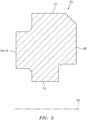
- the fluid may be directed to the seal land 48 (e.g., see FIG. 9 ), a wall 176 of the compartment 30 (e.g., see FIG. 10 ), an oil scoop, a seal seat and/or another component within the bearing compartment 30 or elsewhere that needs cooling and/or lubrication.
- the present disclosure therefore is not limited to delivering the fluid to any particular rotational equipment components.
- each guide rail 52 is described above as guiding movement (e.g., translation) of the seal support assembly 54 and its carrier 102, one or more or each of the guide rails 52 may also or alternatively be configured for guiding movement (e.g., translation) of another component within the rotational equipment (e.g., the gas turbine engine 140).
- the assembly 20 may be included in various turbine engines other than the one described above as well as in other types of rotational equipment.
- the assembly 20, for example, may be included in a geared turbine engine where a gear train connects one or more shafts to one or more rotors in a fan section, a compressor section and/or any other engine section.
- the assembly 20 may be included in a turbine engine configured without a gear train.
- the assembly 20 may be included in a geared or non-geared turbine engine configured with a single spool, with two spools (e.g., see FIG. 8 ), or with more than two spools.
- the turbine engine may be configured as a turbofan engine, a turbojet engine, a propfan engine, a pusher fan engine or any other type of turbine engine. The present disclosure therefore is not limited to any particular types or configurations of turbine engines or rotational equipment.
Landscapes
- Engineering & Computer Science (AREA)
- General Engineering & Computer Science (AREA)
- Mechanical Engineering (AREA)
- Chemical & Material Sciences (AREA)
- Combustion & Propulsion (AREA)
- Oil, Petroleum & Natural Gas (AREA)
- Turbine Rotor Nozzle Sealing (AREA)
- Joints Allowing Movement (AREA)
- Magnetic Bearings And Hydrostatic Bearings (AREA)
- Details And Applications Of Rotary Liquid Pumps (AREA)
Claims (14)
- Baugruppe (20) für Rotationsgeräte, umfassend:eine erste Komponente;eine Statikstruktur (22), umfassend einen Statikstruktur-Flüssigkeitsdurchgang (36);eine Führungsschiene (52), die an der Statikstruktur (22) montiert ist, wobei die Führungsschiene (52) einen Führungsschienen-Flüssigkeitsdurchgang (88) und eine Düse (90) umfasst; undeine zweite Komponente, die mit der Führungsschiene (52) zusammenpasst und dazu konfiguriert ist, sich entlang dieser zu verschieben,wobei die erste Komponente entweder ein Lager (26), einen Dichtungssteg (48) oder eine Abteilwand (176) zum Aufnehmen mindestens eines Lagers umfasst,dadurch gekennzeichnet, dass:
der Führungsschienen-Flüssigkeitsdurchgang (88) fluidmäßig den Statikstruktur-Flüssigkeitsdurchgang (36) mit einer Düsenöffnung (98) der Düse (90) koppelt, und die Düse (90) dazu konfiguriert ist, Flüssigkeit durch die Düsenöffnung (98) auf die erste Komponente zu richten. - Baugruppe (20) nach Anspruch 1, wobei die erste Komponente Folgendes beinhaltet:einen Innenring (43);einen Außenring (42), der den Innenring (43) umgibt; undeine Vielzahl von Lagerelementen (44), die zwischen dem Innenring (43) und dem Außenring (42) angeordnet ist und mit diesen in Eingriff steht.
- Baugruppe nach Anspruch 2, wobei die Düse (90) dazu konfiguriert ist, die Flüssigkeit durch die Düsenöffnung (98) in einen Spalt zwischen dem Innenring (43) und dem Außenring (42) zu richten.
- Baugruppe (20) nach Anspruch 1, 2 oder 3, wobei die zweite Komponente einen Dichtungsträger (102) umfasst.
- Baugruppe (20) nach Anspruch 4, ferner umfassend:einen Dichtungssteg (48), der dazu konfiguriert ist, sich um eine axiale Mittellinie (40) zu drehen; undein Dichtungselement (50), das an dem Dichtungsträger (102) montiert ist, wobei das Dichtungselement (50) dazu konfiguriert ist, dichtend mit dem Dichtungssteg (48) in Eingriff zu kommen.
- Baugruppe (20) nach Anspruch 5, wobei
der Dichtungssteg (48) axial benachbart zu der ersten Komponente ist. - Baugruppe (20) nach Anspruch 5 oder 6, wobei:
das Dichtungselement (50) ein Kohlenstoffdichtungselement umfasst. - Baugruppe (20) nach einem der Ansprüche 4-7, ferner umfassend ein Federelement (130), das dazu konfiguriert ist, den Dichtungsträger (102) von der Statikstruktur (22) weg vorzuspannen.
- Baugruppe (20) nach einem der vorhergehenden Ansprüche, ferner umfassend:eine Vielzahl von Führungsschienen (52), umfassend die Führungsschiene (52), wobei die Vielzahl von Führungsschienen (52) in einer Anordnung um eine Mittellinie (40) angeordnet ist; unddie zweite Komponente, die mit jeder der Vielzahl von Führungsschienen (52) zusammenpasst und dazu konfiguriert ist, sich entlang dieser zu verschieben.
- Baugruppe (20) nach einem der vorhergehenden Ansprüche, wobei die Führungsschiene (52) an der Statikstruktur (22) durch eine Schnittstellenverbindung zwischen der Führungsschiene (52) und der Statikstruktur (22) montiert ist.
- Baugruppe (20) nach Anspruch 10, wobei die Führungsschiene (52) einen hohlen Stift umfasst.
- Baugruppe (20) nach einem der vorhergehenden Ansprüche, wobeidie Führungsschiene (52) sich in Längsrichtung zwischen einem ersten Ende (78) der Führungsschiene und einem zweiten Ende (80) der Führungsschiene erstreckt;die Führungsschiene (52) an der Statikstruktur (22) an dem ersten Ende (78) der Führungsschiene montiert ist; unddie Düse (90) an dem zweiten Ende (80) der Führungsschiene angeordnet ist.
- Baugruppe (20) nach einem der vorangehenden Ansprüche, wobei eine Mittellinie (92) des Führungsschienen-Flüssigkeitsdurchgangs (88) gegenüber einer Mittellinie (96) der Düsenöffnung (98) um einen Winkel (100) winkelversetzt ist.
- Baugruppe (20) nach einem der vorhergehenden Ansprüche, wobeidas Rotationsgerät ein Gasturbinentriebwerk (140) umfasst;die erste Komponente als eine erste Komponente des Gasturbinentriebwerks (140) konfiguriert ist; unddie zweite Komponente als eine zweite Komponente des Gasturbinentriebwerks (140) konfiguriert ist.
Applications Claiming Priority (1)
| Application Number | Priority Date | Filing Date | Title |
|---|---|---|---|
| US16/859,328 US11339719B2 (en) | 2020-04-27 | 2020-04-27 | Fluid delivery system for rotational equipment |
Publications (3)
| Publication Number | Publication Date |
|---|---|
| EP3904644A2 EP3904644A2 (de) | 2021-11-03 |
| EP3904644A3 EP3904644A3 (de) | 2022-02-23 |
| EP3904644B1 true EP3904644B1 (de) | 2024-09-25 |
Family
ID=75728630
Family Applications (1)
| Application Number | Title | Priority Date | Filing Date |
|---|---|---|---|
| EP21170798.9A Active EP3904644B1 (de) | 2020-04-27 | 2021-04-27 | Flüssigkeitsabgabesystem für rotationsgeräte |
Country Status (2)
| Country | Link |
|---|---|
| US (1) | US11339719B2 (de) |
| EP (1) | EP3904644B1 (de) |
Families Citing this family (3)
| Publication number | Priority date | Publication date | Assignee | Title |
|---|---|---|---|---|
| DE102021125138A1 (de) * | 2021-09-28 | 2023-03-30 | Andritz Küsters Gmbh | Dichtungsanordnung und Walze |
| US11739845B2 (en) * | 2021-12-03 | 2023-08-29 | Raytheon Technologies Corporation | Carbon face seal |
| US12571330B2 (en) | 2022-10-27 | 2026-03-10 | Rtx Corporation | Oil nozzle for bearing chamber |
Family Cites Families (33)
| Publication number | Priority date | Publication date | Assignee | Title |
|---|---|---|---|---|
| US3025115A (en) | 1958-04-21 | 1962-03-13 | United Aircraft Corp | Oil-scrubbed bearing race and face seal |
| US3698725A (en) | 1971-01-13 | 1972-10-17 | Giddings & Lewis | Hydrostatic seal for rotary machine tool spindles |
| US3964753A (en) | 1975-01-09 | 1976-06-22 | Avco Corporation | Controlled aperture seal |
| US4406459A (en) | 1982-06-18 | 1983-09-27 | United Technologies Corporation | Oil weepage return for carbon seal plates |
| DE3223703C2 (de) | 1982-06-25 | 1984-05-30 | M.A.N. Maschinenfabrik Augsburg-Nürnberg AG, 4200 Oberhausen | Gasgesperrte Wellendichtung mit radialem Dichtspalt |
| WO1986006136A1 (fr) | 1985-04-12 | 1986-10-23 | Edwin Ott | Moteur diesel convertible pour avions ou pour d'autres applications, a haut rendement, suralimentation et utilisation totale de l'energie optimises |
| US5813674A (en) | 1993-08-10 | 1998-09-29 | United Technologies Corporation | Reverse pressure tolerant seal means |
| US5658127A (en) | 1996-01-26 | 1997-08-19 | Sundstrand Corporation | Seal element cooling in high speed mechanical face seals |
| US20040154578A1 (en) | 2002-02-20 | 2004-08-12 | Weaver Robert R. | Engine connecting rod for high performance applications and method of manufacture |
| US6655693B2 (en) | 2001-04-26 | 2003-12-02 | John Crane Inc. | Non-contacting gas compressor seal |
| US6758598B2 (en) | 2002-08-23 | 2004-07-06 | Pratt & Whitney Canada Corp. | Integrated oil transfer sleeve and bearing |
| CN101701321B (zh) | 2003-07-31 | 2014-03-19 | 株式会社小松制作所 | 烧结滑动部件 |
| CN100417824C (zh) | 2003-11-07 | 2008-09-10 | 日本电产株式会社 | 流体动压轴承及主轴马达 |
| US7410341B2 (en) | 2005-06-22 | 2008-08-12 | Honeywell International, Inc. | Internally-cooled seal housing for turbine engine |
| RU2401953C1 (ru) | 2009-06-25 | 2010-10-20 | Андрей Михаилович Чумохвалов | Опорное устройство |
| FR2961258B1 (fr) | 2010-06-15 | 2012-06-08 | Snecma | Dispositif de guidage et d'etancheite a joint carbone et a palier lisse integre pour une turbomachine |
| IT1400729B1 (it) * | 2010-07-08 | 2013-07-02 | Turboden Srl | Dispositivo di tenuta di fluido per macchine rotanti. |
| US9169780B2 (en) * | 2011-07-15 | 2015-10-27 | Pratt & Whitney Canada Corp. | Connection for generator in a gas turbine engine |
| US8845282B2 (en) | 2011-09-28 | 2014-09-30 | United Technologies Corporation | Seal plate with cooling passage |
| US9989083B2 (en) | 2015-05-26 | 2018-06-05 | Pratt & Whitney Canada Corp. | Seal and bearing assembly for a gas turbine engine and method of assembling same |
| US10047649B2 (en) * | 2015-06-29 | 2018-08-14 | United Technologies Corporation | Concentric axial oil scoop |
| US10288163B2 (en) | 2015-10-23 | 2019-05-14 | General Electric Company | Method and system for a planetary power gearbox static to rotating oil transfer supply |
| US10570776B2 (en) * | 2016-06-07 | 2020-02-25 | United Technologies Corporation | Nozzle for delivering fluid to a component |
| US10329938B2 (en) | 2017-05-31 | 2019-06-25 | General Electric Company | Aspirating face seal starter tooth abradable pocket |
| CN108644019A (zh) | 2018-08-16 | 2018-10-12 | 西北工业大学 | 一种微小型涡轮发动机一体化轴套供油系统 |
| US10767560B2 (en) | 2018-09-11 | 2020-09-08 | Raytheon Technologies Corporation | Bearing compartment oil auto-ignition mitigation |
| US11236636B2 (en) * | 2018-10-29 | 2022-02-01 | Raytheon Technologies Corporation | Oil-cooled carbon seal |
| US11187093B2 (en) | 2019-03-29 | 2021-11-30 | General Electric Company | Face seal assembly with thermal management circuit and an associated method thereof |
| US11125333B2 (en) * | 2019-06-07 | 2021-09-21 | Raytheon Technologies Corporation | Translating fluid coupling device |
| US11371441B2 (en) * | 2019-06-07 | 2022-06-28 | Raytheon Technologies Corporation | Translating fluid delivery device |
| US11624439B2 (en) * | 2020-04-27 | 2023-04-11 | Raytheon Technologies Corporation | Retainer for securing a seal element to a seal carrier |
| US11466778B2 (en) * | 2020-04-27 | 2022-10-11 | Raytheon Technologies Corporation | Rotational equipment seal element with internal fluid passage |
| US11454320B2 (en) * | 2020-04-27 | 2022-09-27 | Raytheon Technologies Corporation | Porous seal element with internal fluid passage |
-
2020
- 2020-04-27 US US16/859,328 patent/US11339719B2/en active Active
-
2021
- 2021-04-27 EP EP21170798.9A patent/EP3904644B1/de active Active
Also Published As
| Publication number | Publication date |
|---|---|
| US11339719B2 (en) | 2022-05-24 |
| EP3904644A2 (de) | 2021-11-03 |
| EP3904644A3 (de) | 2022-02-23 |
| US20210332758A1 (en) | 2021-10-28 |
Similar Documents
| Publication | Publication Date | Title |
|---|---|---|
| US11454320B2 (en) | Porous seal element with internal fluid passage | |
| EP3623588B1 (de) | Wellendichtungsanordnung für einen turbinenmotor | |
| EP3748129B1 (de) | Gleitende fluidkupplungsvorrichtung | |
| US9546560B2 (en) | Compact double grounded mechanical carbon seal | |
| US10174635B2 (en) | Rolling element bearing configured with a gutter and one or more fluid passages | |
| EP3904644B1 (de) | Flüssigkeitsabgabesystem für rotationsgeräte | |
| US11725529B2 (en) | Fluid transfer assembly for rotational equipment | |
| EP3254764B1 (de) | Düse zur bereitstellung von fluid an eine komponente | |
| US11371441B2 (en) | Translating fluid delivery device | |
| EP3954879B1 (de) | Schöpfanordnung für rotierende ausrüstung | |
| US11131388B2 (en) | Seal assembly seal land with a gas flow passage | |
| EP3808943B1 (de) | Flüssigkeitsgekühlte dichtungsleiste für eine gleitringdichtungsanordnung | |
| EP3904732B1 (de) | Rotationsgerätdichtungselement mit innerem fluidkanal | |
| EP3904730B1 (de) | Halter zur befestigung eines dichtungselements an einem dichtungsträger | |
| US12297740B2 (en) | Seal carrier with rolling element guide rail contact |
Legal Events
| Date | Code | Title | Description |
|---|---|---|---|
| PUAI | Public reference made under article 153(3) epc to a published international application that has entered the european phase |
Free format text: ORIGINAL CODE: 0009012 |
|
| STAA | Information on the status of an ep patent application or granted ep patent |
Free format text: STATUS: THE APPLICATION HAS BEEN PUBLISHED |
|
| AK | Designated contracting states |
Kind code of ref document: A2 Designated state(s): AL AT BE BG CH CY CZ DE DK EE ES FI FR GB GR HR HU IE IS IT LI LT LU LV MC MK MT NL NO PL PT RO RS SE SI SK SM TR |
|
| PUAL | Search report despatched |
Free format text: ORIGINAL CODE: 0009013 |
|
| AK | Designated contracting states |
Kind code of ref document: A3 Designated state(s): AL AT BE BG CH CY CZ DE DK EE ES FI FR GB GR HR HU IE IS IT LI LT LU LV MC MK MT NL NO PL PT RO RS SE SI SK SM TR |
|
| RIC1 | Information provided on ipc code assigned before grant |
Ipc: F16N 7/34 20060101ALI20220118BHEP Ipc: F16C 19/06 20060101ALI20220118BHEP Ipc: F16C 33/76 20060101ALI20220118BHEP Ipc: F16C 33/66 20060101ALI20220118BHEP Ipc: F16J 15/34 20060101ALI20220118BHEP Ipc: F16C 37/00 20060101ALI20220118BHEP Ipc: F01D 25/18 20060101ALI20220118BHEP Ipc: F01D 11/00 20060101ALI20220118BHEP Ipc: F01D 25/12 20060101AFI20220118BHEP |
|
| STAA | Information on the status of an ep patent application or granted ep patent |
Free format text: STATUS: REQUEST FOR EXAMINATION WAS MADE |
|
| 17P | Request for examination filed |
Effective date: 20220823 |
|
| RBV | Designated contracting states (corrected) |
Designated state(s): AL AT BE BG CH CY CZ DE DK EE ES FI FR GB GR HR HU IE IS IT LI LT LU LV MC MK MT NL NO PL PT RO RS SE SI SK SM TR |
|
| RAP3 | Party data changed (applicant data changed or rights of an application transferred) |
Owner name: RTX CORPORATION |
|
| RIC1 | Information provided on ipc code assigned before grant |
Ipc: B05B 15/65 20180101ALI20240305BHEP Ipc: F16N 7/34 20060101ALI20240305BHEP Ipc: F16C 19/06 20060101ALI20240305BHEP Ipc: F16C 33/76 20060101ALI20240305BHEP Ipc: F16C 33/66 20060101ALI20240305BHEP Ipc: F16J 15/34 20060101ALI20240305BHEP Ipc: F16C 37/00 20060101ALI20240305BHEP Ipc: F01D 25/18 20060101ALI20240305BHEP Ipc: F01D 11/00 20060101ALI20240305BHEP Ipc: F01D 25/12 20060101AFI20240305BHEP |
|
| GRAP | Despatch of communication of intention to grant a patent |
Free format text: ORIGINAL CODE: EPIDOSNIGR1 |
|
| STAA | Information on the status of an ep patent application or granted ep patent |
Free format text: STATUS: GRANT OF PATENT IS INTENDED |
|
| INTG | Intention to grant announced |
Effective date: 20240422 |
|
| GRAS | Grant fee paid |
Free format text: ORIGINAL CODE: EPIDOSNIGR3 |
|
| GRAA | (expected) grant |
Free format text: ORIGINAL CODE: 0009210 |
|
| STAA | Information on the status of an ep patent application or granted ep patent |
Free format text: STATUS: THE PATENT HAS BEEN GRANTED |
|
| AK | Designated contracting states |
Kind code of ref document: B1 Designated state(s): AL AT BE BG CH CY CZ DE DK EE ES FI FR GB GR HR HU IE IS IT LI LT LU LV MC MK MT NL NO PL PT RO RS SE SI SK SM TR |
|
| REG | Reference to a national code |
Ref country code: GB Ref legal event code: FG4D |
|
| REG | Reference to a national code |
Ref country code: CH Ref legal event code: EP |
|
| REG | Reference to a national code |
Ref country code: DE Ref legal event code: R096 Ref document number: 602021019169 Country of ref document: DE |
|
| REG | Reference to a national code |
Ref country code: IE Ref legal event code: FG4D |
|
| REG | Reference to a national code |
Ref country code: LT Ref legal event code: MG9D |
|
| PG25 | Lapsed in a contracting state [announced via postgrant information from national office to epo] |
Ref country code: NO Free format text: LAPSE BECAUSE OF FAILURE TO SUBMIT A TRANSLATION OF THE DESCRIPTION OR TO PAY THE FEE WITHIN THE PRESCRIBED TIME-LIMIT Effective date: 20241225 |
|
| PG25 | Lapsed in a contracting state [announced via postgrant information from national office to epo] |
Ref country code: GR Free format text: LAPSE BECAUSE OF FAILURE TO SUBMIT A TRANSLATION OF THE DESCRIPTION OR TO PAY THE FEE WITHIN THE PRESCRIBED TIME-LIMIT Effective date: 20241226 Ref country code: FI Free format text: LAPSE BECAUSE OF FAILURE TO SUBMIT A TRANSLATION OF THE DESCRIPTION OR TO PAY THE FEE WITHIN THE PRESCRIBED TIME-LIMIT Effective date: 20240925 |
|
| PG25 | Lapsed in a contracting state [announced via postgrant information from national office to epo] |
Ref country code: BG Free format text: LAPSE BECAUSE OF FAILURE TO SUBMIT A TRANSLATION OF THE DESCRIPTION OR TO PAY THE FEE WITHIN THE PRESCRIBED TIME-LIMIT Effective date: 20240925 |
|
| PG25 | Lapsed in a contracting state [announced via postgrant information from national office to epo] |
Ref country code: LV Free format text: LAPSE BECAUSE OF FAILURE TO SUBMIT A TRANSLATION OF THE DESCRIPTION OR TO PAY THE FEE WITHIN THE PRESCRIBED TIME-LIMIT Effective date: 20240925 |
|
| PG25 | Lapsed in a contracting state [announced via postgrant information from national office to epo] |
Ref country code: RS Free format text: LAPSE BECAUSE OF FAILURE TO SUBMIT A TRANSLATION OF THE DESCRIPTION OR TO PAY THE FEE WITHIN THE PRESCRIBED TIME-LIMIT Effective date: 20241225 |
|
| REG | Reference to a national code |
Ref country code: NL Ref legal event code: MP Effective date: 20240925 |
|
| PG25 | Lapsed in a contracting state [announced via postgrant information from national office to epo] |
Ref country code: RS Free format text: LAPSE BECAUSE OF FAILURE TO SUBMIT A TRANSLATION OF THE DESCRIPTION OR TO PAY THE FEE WITHIN THE PRESCRIBED TIME-LIMIT Effective date: 20241225 Ref country code: NO Free format text: LAPSE BECAUSE OF FAILURE TO SUBMIT A TRANSLATION OF THE DESCRIPTION OR TO PAY THE FEE WITHIN THE PRESCRIBED TIME-LIMIT Effective date: 20241225 Ref country code: LV Free format text: LAPSE BECAUSE OF FAILURE TO SUBMIT A TRANSLATION OF THE DESCRIPTION OR TO PAY THE FEE WITHIN THE PRESCRIBED TIME-LIMIT Effective date: 20240925 Ref country code: GR Free format text: LAPSE BECAUSE OF FAILURE TO SUBMIT A TRANSLATION OF THE DESCRIPTION OR TO PAY THE FEE WITHIN THE PRESCRIBED TIME-LIMIT Effective date: 20241226 Ref country code: FI Free format text: LAPSE BECAUSE OF FAILURE TO SUBMIT A TRANSLATION OF THE DESCRIPTION OR TO PAY THE FEE WITHIN THE PRESCRIBED TIME-LIMIT Effective date: 20240925 Ref country code: BG Free format text: LAPSE BECAUSE OF FAILURE TO SUBMIT A TRANSLATION OF THE DESCRIPTION OR TO PAY THE FEE WITHIN THE PRESCRIBED TIME-LIMIT Effective date: 20240925 |
|
| REG | Reference to a national code |
Ref country code: AT Ref legal event code: MK05 Ref document number: 1726788 Country of ref document: AT Kind code of ref document: T Effective date: 20240925 |
|
| PG25 | Lapsed in a contracting state [announced via postgrant information from national office to epo] |
Ref country code: NL Free format text: LAPSE BECAUSE OF FAILURE TO SUBMIT A TRANSLATION OF THE DESCRIPTION OR TO PAY THE FEE WITHIN THE PRESCRIBED TIME-LIMIT Effective date: 20240925 |
|
| PG25 | Lapsed in a contracting state [announced via postgrant information from national office to epo] |
Ref country code: PT Free format text: LAPSE BECAUSE OF FAILURE TO SUBMIT A TRANSLATION OF THE DESCRIPTION OR TO PAY THE FEE WITHIN THE PRESCRIBED TIME-LIMIT Effective date: 20250127 Ref country code: IS Free format text: LAPSE BECAUSE OF FAILURE TO SUBMIT A TRANSLATION OF THE DESCRIPTION OR TO PAY THE FEE WITHIN THE PRESCRIBED TIME-LIMIT Effective date: 20250125 |
|
| PG25 | Lapsed in a contracting state [announced via postgrant information from national office to epo] |
Ref country code: RO Free format text: LAPSE BECAUSE OF FAILURE TO SUBMIT A TRANSLATION OF THE DESCRIPTION OR TO PAY THE FEE WITHIN THE PRESCRIBED TIME-LIMIT Effective date: 20240925 Ref country code: SM Free format text: LAPSE BECAUSE OF FAILURE TO SUBMIT A TRANSLATION OF THE DESCRIPTION OR TO PAY THE FEE WITHIN THE PRESCRIBED TIME-LIMIT Effective date: 20240925 |
|
| PG25 | Lapsed in a contracting state [announced via postgrant information from national office to epo] |
Ref country code: ES Free format text: LAPSE BECAUSE OF FAILURE TO SUBMIT A TRANSLATION OF THE DESCRIPTION OR TO PAY THE FEE WITHIN THE PRESCRIBED TIME-LIMIT Effective date: 20240925 |
|
| PG25 | Lapsed in a contracting state [announced via postgrant information from national office to epo] |
Ref country code: EE Free format text: LAPSE BECAUSE OF FAILURE TO SUBMIT A TRANSLATION OF THE DESCRIPTION OR TO PAY THE FEE WITHIN THE PRESCRIBED TIME-LIMIT Effective date: 20240925 Ref country code: AT Free format text: LAPSE BECAUSE OF FAILURE TO SUBMIT A TRANSLATION OF THE DESCRIPTION OR TO PAY THE FEE WITHIN THE PRESCRIBED TIME-LIMIT Effective date: 20240925 |
|
| PG25 | Lapsed in a contracting state [announced via postgrant information from national office to epo] |
Ref country code: CZ Free format text: LAPSE BECAUSE OF FAILURE TO SUBMIT A TRANSLATION OF THE DESCRIPTION OR TO PAY THE FEE WITHIN THE PRESCRIBED TIME-LIMIT Effective date: 20240925 Ref country code: PL Free format text: LAPSE BECAUSE OF FAILURE TO SUBMIT A TRANSLATION OF THE DESCRIPTION OR TO PAY THE FEE WITHIN THE PRESCRIBED TIME-LIMIT Effective date: 20240925 |
|
| PG25 | Lapsed in a contracting state [announced via postgrant information from national office to epo] |
Ref country code: IT Free format text: LAPSE BECAUSE OF FAILURE TO SUBMIT A TRANSLATION OF THE DESCRIPTION OR TO PAY THE FEE WITHIN THE PRESCRIBED TIME-LIMIT Effective date: 20240925 Ref country code: SK Free format text: LAPSE BECAUSE OF FAILURE TO SUBMIT A TRANSLATION OF THE DESCRIPTION OR TO PAY THE FEE WITHIN THE PRESCRIBED TIME-LIMIT Effective date: 20240925 |
|
| REG | Reference to a national code |
Ref country code: DE Ref legal event code: R097 Ref document number: 602021019169 Country of ref document: DE |
|
| PGFP | Annual fee paid to national office [announced via postgrant information from national office to epo] |
Ref country code: DE Payment date: 20250319 Year of fee payment: 5 |
|
| PG25 | Lapsed in a contracting state [announced via postgrant information from national office to epo] |
Ref country code: DK Free format text: LAPSE BECAUSE OF FAILURE TO SUBMIT A TRANSLATION OF THE DESCRIPTION OR TO PAY THE FEE WITHIN THE PRESCRIBED TIME-LIMIT Effective date: 20240925 |
|
| PLBE | No opposition filed within time limit |
Free format text: ORIGINAL CODE: 0009261 |
|
| STAA | Information on the status of an ep patent application or granted ep patent |
Free format text: STATUS: NO OPPOSITION FILED WITHIN TIME LIMIT |
|
| 26N | No opposition filed |
Effective date: 20250626 |
|
| PG25 | Lapsed in a contracting state [announced via postgrant information from national office to epo] |
Ref country code: SE Free format text: LAPSE BECAUSE OF FAILURE TO SUBMIT A TRANSLATION OF THE DESCRIPTION OR TO PAY THE FEE WITHIN THE PRESCRIBED TIME-LIMIT Effective date: 20240925 |
|
| REG | Reference to a national code |
Ref country code: CH Ref legal event code: H13 Free format text: ST27 STATUS EVENT CODE: U-0-0-H10-H13 (AS PROVIDED BY THE NATIONAL OFFICE) Effective date: 20251125 |
|
| PG25 | Lapsed in a contracting state [announced via postgrant information from national office to epo] |
Ref country code: LU Free format text: LAPSE BECAUSE OF NON-PAYMENT OF DUE FEES Effective date: 20250427 |
|
| PG25 | Lapsed in a contracting state [announced via postgrant information from national office to epo] |
Ref country code: MC Free format text: LAPSE BECAUSE OF FAILURE TO SUBMIT A TRANSLATION OF THE DESCRIPTION OR TO PAY THE FEE WITHIN THE PRESCRIBED TIME-LIMIT Effective date: 20240925 |
|
| REG | Reference to a national code |
Ref country code: BE Ref legal event code: MM Effective date: 20250430 |
|
| PG25 | Lapsed in a contracting state [announced via postgrant information from national office to epo] |
Ref country code: HR Free format text: LAPSE BECAUSE OF FAILURE TO SUBMIT A TRANSLATION OF THE DESCRIPTION OR TO PAY THE FEE WITHIN THE PRESCRIBED TIME-LIMIT Effective date: 20240925 |
|
| PG25 | Lapsed in a contracting state [announced via postgrant information from national office to epo] |
Ref country code: BE Free format text: LAPSE BECAUSE OF NON-PAYMENT OF DUE FEES Effective date: 20250430 |
|
| PG25 | Lapsed in a contracting state [announced via postgrant information from national office to epo] |
Ref country code: CH Free format text: LAPSE BECAUSE OF NON-PAYMENT OF DUE FEES Effective date: 20250430 |
|
| PGFP | Annual fee paid to national office [announced via postgrant information from national office to epo] |
Ref country code: GB Payment date: 20260319 Year of fee payment: 6 |
|
| PG25 | Lapsed in a contracting state [announced via postgrant information from national office to epo] |
Ref country code: IE Free format text: LAPSE BECAUSE OF NON-PAYMENT OF DUE FEES Effective date: 20250427 |
|
| PGFP | Annual fee paid to national office [announced via postgrant information from national office to epo] |
Ref country code: FR Payment date: 20260320 Year of fee payment: 6 |