EP4575044A1 - Electrolysis device, stirring deposition equipment, circulating deposition system and electrolysis method - Google Patents
Electrolysis device, stirring deposition equipment, circulating deposition system and electrolysis method Download PDFInfo
- Publication number
- EP4575044A1 EP4575044A1 EP23218994.4A EP23218994A EP4575044A1 EP 4575044 A1 EP4575044 A1 EP 4575044A1 EP 23218994 A EP23218994 A EP 23218994A EP 4575044 A1 EP4575044 A1 EP 4575044A1
- Authority
- EP
- European Patent Office
- Prior art keywords
- cathode plate
- working fluid
- magnetic
- deposition
- magnetic component
- Prior art date
- Legal status (The legal status is an assumption and is not a legal conclusion. Google has not performed a legal analysis and makes no representation as to the accuracy of the status listed.)
- Pending
Links
Images



Classifications
-
- C—CHEMISTRY; METALLURGY
- C25—ELECTROLYTIC OR ELECTROPHORETIC PROCESSES; APPARATUS THEREFOR
- C25C—PROCESSES FOR THE ELECTROLYTIC PRODUCTION, RECOVERY OR REFINING OF METALS; APPARATUS THEREFOR
- C25C1/00—Electrolytic production, recovery or refining of metals by electrolysis of solutions
- C25C1/06—Electrolytic production, recovery or refining of metals by electrolysis of solutions or iron group metals, refractory metals or manganese
-
- C—CHEMISTRY; METALLURGY
- C25—ELECTROLYTIC OR ELECTROPHORETIC PROCESSES; APPARATUS THEREFOR
- C25C—PROCESSES FOR THE ELECTROLYTIC PRODUCTION, RECOVERY OR REFINING OF METALS; APPARATUS THEREFOR
- C25C3/00—Electrolytic production, recovery or refining of metals by electrolysis of melts
- C25C3/34—Electrolytic production, recovery or refining of metals by electrolysis of melts of metals not provided for in groups C25C3/02 - C25C3/32
-
- C—CHEMISTRY; METALLURGY
- C25—ELECTROLYTIC OR ELECTROPHORETIC PROCESSES; APPARATUS THEREFOR
- C25C—PROCESSES FOR THE ELECTROLYTIC PRODUCTION, RECOVERY OR REFINING OF METALS; APPARATUS THEREFOR
- C25C7/00—Constructional parts, or assemblies thereof, of cells; Servicing or operating of cells
- C25C7/06—Operating or servicing
-
- C—CHEMISTRY; METALLURGY
- C25—ELECTROLYTIC OR ELECTROPHORETIC PROCESSES; APPARATUS THEREFOR
- C25D—PROCESSES FOR THE ELECTROLYTIC OR ELECTROPHORETIC PRODUCTION OF COATINGS; ELECTROFORMING; APPARATUS THEREFOR
- C25D17/00—Constructional parts, or assemblies thereof, of cells for electrolytic coating
-
- C—CHEMISTRY; METALLURGY
- C25—ELECTROLYTIC OR ELECTROPHORETIC PROCESSES; APPARATUS THEREFOR
- C25D—PROCESSES FOR THE ELECTROLYTIC OR ELECTROPHORETIC PRODUCTION OF COATINGS; ELECTROFORMING; APPARATUS THEREFOR
- C25D17/00—Constructional parts, or assemblies thereof, of cells for electrolytic coating
- C25D17/02—Tanks; Installations therefor
-
- C—CHEMISTRY; METALLURGY
- C25—ELECTROLYTIC OR ELECTROPHORETIC PROCESSES; APPARATUS THEREFOR
- C25D—PROCESSES FOR THE ELECTROLYTIC OR ELECTROPHORETIC PRODUCTION OF COATINGS; ELECTROFORMING; APPARATUS THEREFOR
- C25D17/00—Constructional parts, or assemblies thereof, of cells for electrolytic coating
- C25D17/10—Electrodes, e.g. composition, counter electrode
- C25D17/12—Shape or form
-
- C—CHEMISTRY; METALLURGY
- C25—ELECTROLYTIC OR ELECTROPHORETIC PROCESSES; APPARATUS THEREFOR
- C25D—PROCESSES FOR THE ELECTROLYTIC OR ELECTROPHORETIC PRODUCTION OF COATINGS; ELECTROFORMING; APPARATUS THEREFOR
- C25D21/00—Processes for servicing or operating cells for electrolytic coating
- C25D21/10—Agitating of electrolytes; Moving of racks
-
- C—CHEMISTRY; METALLURGY
- C25—ELECTROLYTIC OR ELECTROPHORETIC PROCESSES; APPARATUS THEREFOR
- C25D—PROCESSES FOR THE ELECTROLYTIC OR ELECTROPHORETIC PRODUCTION OF COATINGS; ELECTROFORMING; APPARATUS THEREFOR
- C25D5/00—Electroplating characterised by the process; Pretreatment or after-treatment of workpieces
- C25D5/007—Electroplating using magnetic fields, e.g. magnets
Definitions
- the disclosure relates to an electrolysis device, a stirring deposition equipment, a circulating deposition system, and an electrolysis method.
- Alkaline electrolytic iron precipitation has the characteristics of low carbon emission in the process, low environmental pollution, and high purity with low impurities in the product; however, it is limited by the constraints of traditional technology, resulting in low production efficiency.
- the disclosure provides an electrolysis device that effectively improves output efficiency.
- the disclosure provides a stirring deposition equipment that improves output efficiency.
- the disclosure provides a circulating deposition system that effectively improves deposition efficiency.
- the disclosure provides an electrolysis method that effectively improves output efficiency.
- the disclosure provides an electrolysis device configured to electro-precipitate a magnetic deposition from a working fluid.
- the electrolysis device includes an anode plate, a cathode plate, and a magnetic component.
- the cathode plate and the anode plate are disposed correspondingly, and the magnetic component is disposed on a side of the cathode plate relatively away from the anode plate.
- the working fluid flows between the anode plate and the cathode plate, and an oxidation-reduction reaction occurs between the anode plate and the cathode plate.
- the magnetic component attaches the magnetic deposition resolved from the working fluid onto a surface of the cathode plate facing the anode plate.
- the magnetic deposition includes a product and a half-reactant.
- the disclosure provides a stirring deposition equipment including: a stirring tank, the above-mentioned electrolysis device, a stirring rod, and a rotating electrode.
- the stirring tank is filled with the working fluid.
- the stirring rod is tilted at an angle relative to a tank bottom of the stirring tank, extends into the stirring tank, and is immersed in the working fluid.
- the anode plate of the electrolysis device is disposed in the stirring tank, and the cathode plate and the magnetic component of the electrolysis device are disposed at an end of the stirring rod extending into the stirring tank.
- the rotating electrode is connected to the stirring rod.
- the disclosure provides a circulating deposition system adapted for circulating a working fluid therein.
- the circulating deposition system includes a stirring tank, a stirring rod, an electrolysis device, a first pump, and a pipeline.
- the stirring tank is filled with the working fluid.
- the stirring rod extends into the stirring tank and is immersed in the working fluid.
- the electrolysis device includes: a plating tank, an anode plate, a cathode plate, and a magnetic component.
- the cathode plate is disposed at a tank bottom of the plating tank, the anode plate is disposed corresponding to the cathode plate, and the magnetic component is disposed outside the tank bottom of the plating tank.
- the pipeline connects the stirring tank, the plating tank, and the first pump.
- the working fluid that flows between the anode plate and the cathode plate undergoes an oxidation-reduction reaction between the anode plate and the cathode plate, and the magnetic component attaches the magnetic deposition resolved from the working fluid onto a surface of the cathode plate facing the anode plate.
- the magnetic deposition includes a product and a half-reactant.
- An electrolysis method for electro-precipitating a magnetic deposition at least includes: providing an electrolysis device.
- the electrolysis device includes an anode plate, a cathode plate disposed corresponding to the anode plate, and a magnetic component disposed on a side of the cathode plate relatively away from the anode plate.
- An oxidation-reduction reaction occurs when a working fluid flows through the anode plate and the cathode plate, and the magnetic component attaches the magnetic deposition resolved from the working fluid onto a surface of the cathode plate facing the anode plate.
- the magnetic deposition includes a product and a half-reactant.
- the electrolysis device and the electrolysis method in the disclosure may effectively improve the electrolysis production efficiency through the configuration of the magnetic component, thereby effectively increase the production efficiency of the stirring deposition equipment and circulating deposition system applying this electrolysis device and electrolysis method.
- FIG. 1 is a schematic view of the electrolysis device according to the disclosure.
- an electrolysis device 10 of the disclosure is adapted for being electrically connected to a power supply device 18 to electro-precipitate a magnetic deposition M in a working fluid F.
- the working fluid F is a mixture containing iron mineral (hematite%), sodium hydroxide (NaOH), and water (H 2 O).
- This electrolysis device 10 includes an anode plate 11, a cathode plate 12, and a magnetic component 13.
- the cathode plate 12 and the anode plate 11 are disposed correspondingly, and the magnetic component 13 is disposed on a side of the cathode plate 12 relatively away from the anode plate 11.
- the working fluid F flows between the anode plate 11 and the cathode plate 12, and an oxidation-reduction reaction occurs between the anode plate 11 and the cathode plate 12.
- the magnetic component 13 attaches the magnetic deposition M resolved from the working fluid F onto a surface of the cathode plate 12 facing the anode plate 11.
- the magnetic deposition M includes a product P and a half-reactant H.
- the above-mentioned product P is a metal (e.g., iron (Fe))
- the half-reactant H is a metal compound (e.g., iron(II,III) oxide (Fe 3 O 4 )).
- the half-reactant H is a physical substance, and in the drawings of the disclosure, the half-reactant H is represented by a dotted circle.
- the magnetic component 13 is a permanent magnet or an electromagnet, and when the magnetic component 13 is an electromagnet, the magnetic force of the electromagnet may be controlled by controlling the current flowing through the electromagnet.
- the above-mentioned cathode plate 12 has a first edge 121 and a second edge 122, and the magnetic component 13 also has a first edge 131 and a second edge 132, the first edge 131 of the magnetic component 13 is disposed corresponding to the first edge 121 of cathode plate 12, and the second edge 132 of the magnetic component 13 is disposed corresponding to the second edge 122 of the cathode plate 12.
- an orthographic projection range of the magnetic component 13 falls within an orthographic projection range of the cathode plate 12. That is, in a flowing direction of the working fluid F, a length of the magnetic component 13 is less than a length of the cathode plate 12.
- a distance g1 is provided from the first edge 131 of the magnetic component 13 to the first edge 121 of the cathode plate 12, and a distance g2 is provided from the second edge 132 of the magnetic component 13 to the second edge 122 of the cathode plate 12.
- the distance g1 from the first edge 131 of the magnetic component 13 to the first edge 121 of the cathode plate 12 may be the same as the distance g2 from the second edge 132 of the magnetic component 13 to the second edge 122 of the cathode plate 12.
- the distances g1 and g2 may be adjusted to be different according to actual needs.
- the distance g1 from the first edge 131 of the magnetic component 13 to the first edge 121 of the cathode plate 12 is greater than a thickness t of the magnetic component 13.
- the range of the magnetic field provided by the magnetic component 13 is smaller than the range of the electric field formed after the electrolysis device 10 is energized.
- the electrolysis device 10 when using the above-mentioned electrolysis device 10 for electrolysis, the electrolysis device 10 is energized and the working fluid F flows between the anode plate 11 and the cathode plate 12.
- This working fluid F is a mud mixture (hereinafter referred to as mud) containing iron oxide, sodium hydroxide (NaOH), and water (H 2 O).
- mud a mud mixture
- the oxidation-reduction reaction occurs when the mud flows through the anode plate 11 and the cathode plate 12, and the magnetic component 13 attaches the magnetic deposition M resolved from the working fluid F onto a surface of the cathode plate 12 facing the anode plate 11.
- This magnetic deposition M includes the half-reactant H, which is the iron(II,III) oxide (Fe 3 O 4 ), and the product P, which is iron.
- the electrolysis device 10 of this embodiment Compared to the electrolysis device 10 without the magnetic component 13, since the working fluid F continuously flows into the area between the anode plate 11 and the cathode plate 12, the working fluid F washes away a part of the magnetic deposition M deposited on the surface of the cathode plate 12.
- the magnetic deposition M including the iron product P and the half-reactant H resolved by the oxidation-reduction reaction is attracted by the magnetic force of the magnetic component 13 and may resist being washed away by the working fluid F to be deposited on the surface of the cathode plate 12 facing the anode plate 11.
- the chance of the magnetic deposition M being washed away by the working fluid F may be reduced, and the production efficiency of the electrolysis output may be effectively improved.
- the magnetic component 13 attracts the magnetic deposition M, thereby reducing the gap caused by the density change, crowding out the attracted mud raw materials, and crowding out the by-products such as oxygen and electrolyzed water hydrogen, so that the magnetic deposition M deposited on the surface of the cathode plate 12 may be arranged in a denser structure.
- the electrolysis device 10 since the electromagnetism may influence or convert each other, in order to prevent the magnetic force of the magnetic component 13 from affecting the electric field, the electrolysis device 10 further includes an electrical insulation layer 14.
- FIG. 2 is a schematic view of the electrolysis device 10 in FIG. 1 which further includes the electrical insulation layer 14.
- the electrolysis device 10 further includes an electrical insulation layer 14 wrapped around the outer circumference of the magnetic component 13.
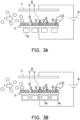
- the configuration of the electrical insulation layer 14 may isolate the influence of the electric field on the magnetic force, thereby avoiding the instability of the current affecting the magnetic force and making the efficiency of the electrolysis output unstable.
- FIG. 3A is a schematic view where the magnetic component 13 is set to multiple
- FIG. 3B is a schematic view of the electrolysis device 10 in FIG. 3A which further includes the electrical insulation layer 14.
- the amount of the magnetic component 13a set in this embodiment is not limited to one as shown in the embodiment of FIG. 1 , but may be set to multiple.
- These magnetic components 13a are arranged in an array, and the outer circumference of each of the magnetic components 13a may also be wrapped with an electrical insulation layer 14a.
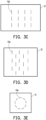
- FIG. 3C to FIG. 3E are schematic views of multiple magnetic components 13 in FIG. 3A arranged in different arrays.
- the above-mentioned magnetic components 13a may be arranged in an array as shown in FIG. 3C , in a staggered array as shown in FIG. 3D , or in a ringshaped array as shown in FIG. 3E .
- Those skilled in the art may know from the foregoing that the arrangement of the magnetic components 13a may be varied in accordance with actual needs.
- the magnetic components 13a in FIG. 3C to FIG. 3E are shown as lines schematically and are not the actual shapes of the real magnetic components 13a.
- FIG. 4 is a schematic view of the stirring deposition equipment according to the second embodiment of the disclosure.
- the stirring deposition equipment 20 of this embodiment includes a stirring tank 21, an electrolysis device 10b, a stirring rod 22, and a rotating electrode 23.
- the working fluid F is filled in the stirring tank 21, and the anode plate 11 of the electrolysis device 10b is fixed in the stirring tank 21.
- the stirring rod 22 is tilted at an angle relative to a tank bottom of the stirring tank 21, extends into the stirring tank 21, and is immersed in the working fluid F.
- a range of the angle ⁇ of the stirring rod 22 tilted relative to the tank bottom of the stirring tank 21 is between 0 and 60 degrees.
- the cathode plate 12 and the magnetic component 13 of the electrolysis device 10b are disposed at an end of the stirring rod 22 extending into the stirring tank 21.
- the electrolysis device 10b and the rotating electrode 23 are energized.
- the rotating electrode 23 drives the stirring rod 22 to rotate and stir the working fluid F in the stirring tank 21.
- the electrolysis device 10b causes the working fluid F to undergo an oxidation-reduction reaction in the stirring tank 21 to resolve the magnetic deposition M, such as the half-reactant H, which is the iron(II,III) oxide (Fe 3 O 4 ), and the product P, which is iron.
- These magnetic deposition M are deposited on the cathode plate 12.
- the magnetic component 13 is disposed on the side of the cathode plate 12 opposite to the side to which the stirring bar 22 is connected.
- the magnetic component 13 may effectively attract and arrange the product P and a small amount of the half-reactant H electro-precipitated from the oxidation-reduction reaction on the cathode plate 12 in a relatively dense structure.
- the rotating electrode 23 and the electrolysis device 10b may be electrically connected to the same power supply device 18 to be driven simultaneously.
- the rotating electrode 23 and the electrolysis device 10b may be electrically connected to different power supply devices 18 to be driven separately, or electrically connected to the same power supply device 18 but individually driven by different control switches.
- a heater 24 is provided on the bottom side of the stirring tank 21 of this embodiment, where the heater 24 is configured to heat the working fluid F to improve the fluidity of the working fluid F.
- this embodiment takes the heater 24 provided on the bottom side of the stirring tank 21 as an example, it is not limited thereto.
- the heater 24 may also be provided at any of the four side walls of the heater 24 connected to the bottom.
- the amount of the heater 24 is not limited to one, as in the example in this embodiment, and the amount of heater 24 may also be more than one.
- FIG. 5 is a schematic view of the circulating deposition system according to the third embodiment of the disclosure.
- a circulating deposition system 30 of this embodiment is adapted for circulating the working fluid F therein.
- the circulating deposition system 30 includes a stirring tank 31, a stirring rod 32, an electrolysis device 10c, a first pump P1, and a pipeline 35.
- the stirring tank 31 is filled with the working fluid F.
- the working fluid F is a mixture containing iron mineral (hematite%), sodium hydroxide (NaOH), and water (H 2 O).
- the stirring rod 32 extends into the stirring tank 31 and is immersed in the working fluid F.
- the electrolysis device 10c includes a plating tank 15, an anode plate 11, a cathode plate 12, and a magnetic component 13.
- the cathode plate 12 is disposed at a tank bottom of the plating tank 15, the anode plate 11 is disposed corresponding to the cathode plate 12, and the magnetic component 13 is disposed outside the tank bottom of the plating tank 15.
- the pipeline 35 is connected to the stirring tank 31, the plating tank 15, and the first pump P1.
- the magnetic component 13 attaches the magnetic deposition M (as shown in FIG. 1 ) resolved from the working fluid F onto a surface of the cathode plate 12 facing the anode plate 11.
- the resolved magnetic deposition M includes the half-reactant H, which is the iron(II,III) oxide (Fe 3 O 4 ), and the product P, which is iron.
- the longitudinal direction L1 of the anode plate 11 is perpendicular to the longitudinal direction L2 of the cathode plate 12. In other words, multiple anode plates 11 are arranged along the longitudinal direction L2 of the cathode plate 12.
- the circulating deposition system 30 further includes multiple valves V1, V2, V3, and V4, of which the first valve V1 is disposed between the stirring tank 31 and the plating tank 15, and the second valve V2 is disposed between the first pump P1 and the stirring tank 31.
- the configuration of the first valve V1 and the second valve V2 may not only control the flow rate of the working fluid F in the pipeline 35, but also prevent the backflow of the working fluid F.
- the circulating deposition system 30 may further include a heater 36, which is disposed at the stirring tank 31.
- the heater 36 is disposed in the stirring tank 31, but is not limited thereto.
- the position and amount of the heater 36 may also be the same as the position and amount of the heater 24 in the second embodiment.
- the first valve V1 of the stirring tank 31 is opened so that the working fluid F may flow from the stirring tank 31 into the plating tank 15 for oxidation-reduction reaction to electro-precipitate the magnetic deposition M, then the working fluid F flows out from the plating tank 15 and flows through the pipeline 35 to the first pump P1, and then passes through the second valve V2 and returns to the stirring tank 31.
- the magnetic deposition M such as the product P of iron and the half-reactant H of the iron(II,III) oxide (Fe 3 O 4 ), is electro-precipitated.
- the electro-precipitated magnetic deposition M most of the product P and a small amount of the half-reactant H are deposited on the surface of the cathode plate 12 facing the anode plate 11.
- the magnetic deposition M electro-precipitated from the oxidation-reduction reaction may be deposited on the surface of the cathode plate 12 in a relatively dense structure.
- the magnetic force of the magnetic component 13 may attract the magnetic deposition M present in the working fluid F, reducing the amount of the magnetic deposition M carried away by the working fluid F due to the flow and effectively improving the deposition efficiency.
- the circulating deposition system 30 may further include a cleaning tank 37 connected to the plating tank 15 and the first pump P1, a second pump P2 disposed between the cleaning tank 37 and the plating tank 15, a third valve V3 disposed between the cleaning tank 37 and the plating tank 15, and a fourth valve V4 disposed between the first pump P1 and the cleaning tank 37.
- the cleaning tank 37 provides a second working fluid F2.
- the second working fluid F2 flows out from the cleaning tank 37, passes through the second pump P2 and the third valve V3, and then enters the plating tank 15 to wash the cathode plate 12 on which the magnetic deposition M is deposited. Afterwards, the second working fluid F2 flows out from the plating tank 15 and flows back to the cleaning tank 37 through the first pump P1 and the fourth valve V4.
- the electrolysis device and the electrolysis method in the disclosure may use the magnetic force to attract the magnetic deposition (including the product and the half-reactant) electro-precipitated from the working fluid through the configuration of the magnetic component, thereby effectively improving the efficiency of magnetic deposition on the cathode plate.
- the influence of the magnetic force allows the magnetic deposition to be deposited on the cathode plate with a denser structure, thereby improving the deposition effect.
- the stirring deposition equipment and the circulating deposition system using this electrolysis device and electrolysis method may effectively increase the output efficiency.
Landscapes
- Chemical & Material Sciences (AREA)
- Engineering & Computer Science (AREA)
- Chemical Kinetics & Catalysis (AREA)
- Electrochemistry (AREA)
- Materials Engineering (AREA)
- Metallurgy (AREA)
- Organic Chemistry (AREA)
- Electroplating Methods And Accessories (AREA)
Abstract
An electrolysis device (10, 10b, 10c), a stirring deposition equipment (20), a circulating deposition system (30), and an electrolysis method are provided. The electrolysis device is configured to electro-precipitate a magnetic deposition (M) from a working fluid (F). The electrolysis device includes an anode plate (11), a cathode plate (12), and a magnetic component (13, 13a). The cathode plate and the anode plate are disposed correspondingly, and the magnetic component is disposed on a side of the cathode plate relatively away from the anode plate. The working fluid flows between the anode plate and the cathode plate, and an oxidation-reduction reaction occurs between the anode plate and the cathode plate. The magnetic component attaches the magnetic deposition resolved from the working fluid onto a surface of the cathode plate facing the anode plate. The magnetic deposition includes a product (P) and a half-reactant (H).
Description
- The disclosure relates to an electrolysis device, a stirring deposition equipment, a circulating deposition system, and an electrolysis method.
- Alkaline electrolytic iron precipitation has the characteristics of low carbon emission in the process, low environmental pollution, and high purity with low impurities in the product; however, it is limited by the constraints of traditional technology, resulting in low production efficiency.
- Specifically, in the process of reducing mineral raw materials to ferrous metal, due to factors such as changes in material density along with the formation of gas by-products that are swept up into the working fluid, the products are formed in a loose, porous structure or powder state that can easily be carried away by the working fluid, resulting in a decrease in the efficiency of electrolytic iron production.
- The disclosure provides an electrolysis device that effectively improves output efficiency.
- The disclosure provides a stirring deposition equipment that improves output efficiency.
- The disclosure provides a circulating deposition system that effectively improves deposition efficiency.
- The disclosure provides an electrolysis method that effectively improves output efficiency.
- The disclosure provides an electrolysis device configured to electro-precipitate a magnetic deposition from a working fluid. The electrolysis device includes an anode plate, a cathode plate, and a magnetic component. The cathode plate and the anode plate are disposed correspondingly, and the magnetic component is disposed on a side of the cathode plate relatively away from the anode plate. The working fluid flows between the anode plate and the cathode plate, and an oxidation-reduction reaction occurs between the anode plate and the cathode plate. The magnetic component attaches the magnetic deposition resolved from the working fluid onto a surface of the cathode plate facing the anode plate. The magnetic deposition includes a product and a half-reactant.
- The disclosure provides a stirring deposition equipment including: a stirring tank, the above-mentioned electrolysis device, a stirring rod, and a rotating electrode. The stirring tank is filled with the working fluid. The stirring rod is tilted at an angle relative to a tank bottom of the stirring tank, extends into the stirring tank, and is immersed in the working fluid. The anode plate of the electrolysis device is disposed in the stirring tank, and the cathode plate and the magnetic component of the electrolysis device are disposed at an end of the stirring rod extending into the stirring tank. The rotating electrode is connected to the stirring rod.
- The disclosure provides a circulating deposition system adapted for circulating a working fluid therein. In the flowing direction of the working fluid, the circulating deposition system includes a stirring tank, a stirring rod, an electrolysis device, a first pump, and a pipeline. The stirring tank is filled with the working fluid. The stirring rod extends into the stirring tank and is immersed in the working fluid. The electrolysis device includes: a plating tank, an anode plate, a cathode plate, and a magnetic component. The cathode plate is disposed at a tank bottom of the plating tank, the anode plate is disposed corresponding to the cathode plate, and the magnetic component is disposed outside the tank bottom of the plating tank. The pipeline connects the stirring tank, the plating tank, and the first pump. The working fluid that flows between the anode plate and the cathode plate undergoes an oxidation-reduction reaction between the anode plate and the cathode plate, and the magnetic component attaches the magnetic deposition resolved from the working fluid onto a surface of the cathode plate facing the anode plate. The magnetic deposition includes a product and a half-reactant.
- An electrolysis method for electro-precipitating a magnetic deposition at least includes: providing an electrolysis device. The electrolysis device includes an anode plate, a cathode plate disposed corresponding to the anode plate, and a magnetic component disposed on a side of the cathode plate relatively away from the anode plate. An oxidation-reduction reaction occurs when a working fluid flows through the anode plate and the cathode plate, and the magnetic component attaches the magnetic deposition resolved from the working fluid onto a surface of the cathode plate facing the anode plate. The magnetic deposition includes a product and a half-reactant.
- Based on the above, the electrolysis device and the electrolysis method in the disclosure may effectively improve the electrolysis production efficiency through the configuration of the magnetic component, thereby effectively increase the production efficiency of the stirring deposition equipment and circulating deposition system applying this electrolysis device and electrolysis method.
-
-
FIG. 1 is a schematic view of the electrolysis device according to the disclosure. -
FIG. 2 is a schematic view of the electrolysis device inFIG. 1 which further includes the electrical insulation layer. -
FIG. 3A is a schematic view where the magnetic component is set to multiple. -
FIG. 3B is a schematic view of the electrolysis device inFIG. 3A which further includes the electrical insulation layer. -
FIG. 3C to FIG. 3E are schematic views of multiplemagnetic components 13 inFIG. 3A arranged in different arrays. -
FIG. 4 is a schematic view of the stirring deposition equipment according to the second embodiment of the disclosure. -
FIG. 5 is a schematic view of the circulating deposition system according to the third embodiment of the disclosure. -
FIG. 1 is a schematic view of the electrolysis device according to the disclosure. Referring toFIG. 1 , anelectrolysis device 10 of the disclosure is adapted for being electrically connected to apower supply device 18 to electro-precipitate a magnetic deposition M in a working fluid F. The working fluid F is a mixture containing iron mineral (hematite...), sodium hydroxide (NaOH), and water (H2O). Thiselectrolysis device 10 includes ananode plate 11, acathode plate 12, and amagnetic component 13. Thecathode plate 12 and theanode plate 11 are disposed correspondingly, and themagnetic component 13 is disposed on a side of thecathode plate 12 relatively away from theanode plate 11. The working fluid F flows between theanode plate 11 and thecathode plate 12, and an oxidation-reduction reaction occurs between theanode plate 11 and thecathode plate 12. Themagnetic component 13 attaches the magnetic deposition M resolved from the working fluid F onto a surface of thecathode plate 12 facing theanode plate 11. The magnetic deposition M includes a product P and a half-reactant H. The above-mentioned product P is a metal (e.g., iron (Fe)), and the half-reactant H is a metal compound (e.g., iron(II,III) oxide (Fe3O4)). It should be noted that the half-reactant H is a physical substance, and in the drawings of the disclosure, the half-reactant H is represented by a dotted circle. - In this embodiment, the
magnetic component 13 is a permanent magnet or an electromagnet, and when themagnetic component 13 is an electromagnet, the magnetic force of the electromagnet may be controlled by controlling the current flowing through the electromagnet. - The above-mentioned
cathode plate 12 has afirst edge 121 and asecond edge 122, and themagnetic component 13 also has afirst edge 131 and asecond edge 132, thefirst edge 131 of themagnetic component 13 is disposed corresponding to thefirst edge 121 ofcathode plate 12, and thesecond edge 132 of themagnetic component 13 is disposed corresponding to thesecond edge 122 of thecathode plate 12. In this embodiment, an orthographic projection range of themagnetic component 13 falls within an orthographic projection range of thecathode plate 12. That is, in a flowing direction of the working fluid F, a length of themagnetic component 13 is less than a length of thecathode plate 12. - Specifically, a distance g1 is provided from the
first edge 131 of themagnetic component 13 to thefirst edge 121 of thecathode plate 12, and a distance g2 is provided from thesecond edge 132 of themagnetic component 13 to thesecond edge 122 of thecathode plate 12. By providing the distances g1 and g2, the magnetic deposition M may be prevented from being concentratedly deposited at the edges of thecathode plate 12. - In addition, the distance g1 from the
first edge 131 of themagnetic component 13 to thefirst edge 121 of thecathode plate 12 may be the same as the distance g2 from thesecond edge 132 of themagnetic component 13 to thesecond edge 122 of thecathode plate 12. The distances g1 and g2 may be adjusted to be different according to actual needs. - Accordingly, in this embodiment, the distance g1 from the
first edge 131 of themagnetic component 13 to thefirst edge 121 of thecathode plate 12 is greater than a thickness t of themagnetic component 13. In other words, the range of the magnetic field provided by themagnetic component 13 is smaller than the range of the electric field formed after theelectrolysis device 10 is energized. - Continuing to refer to
FIG. 1 , when using the above-mentionedelectrolysis device 10 for electrolysis, theelectrolysis device 10 is energized and the working fluid F flows between theanode plate 11 and thecathode plate 12. This working fluid F is a mud mixture (hereinafter referred to as mud) containing iron oxide, sodium hydroxide (NaOH), and water (H2O). The oxidation-reduction reaction occurs when the mud flows through theanode plate 11 and thecathode plate 12, and themagnetic component 13 attaches the magnetic deposition M resolved from the working fluid F onto a surface of thecathode plate 12 facing theanode plate 11. This magnetic deposition M includes the half-reactant H, which is the iron(II,III) oxide (Fe3O4), and the product P, which is iron. - It may be seen from
FIG. 1 that by disposing of themagnetic component 13 on the side of thecathode plate 12 relatively away from theanode plate 11, the magnetic deposition M resolved through the oxidation-reduction reaction is attracted by the magnetic force of themagnetic component 13 and deposited on the surface of thecathode plate 12 facing theanode plate 11. Other by-products produced by the oxidation-reduction reaction, such as oxygen and electrolyzed water hydrogen, are taken away by the flowing working fluid F. - Compared to the
electrolysis device 10 without themagnetic component 13, since the working fluid F continuously flows into the area between theanode plate 11 and thecathode plate 12, the working fluid F washes away a part of the magnetic deposition M deposited on the surface of thecathode plate 12. In contrast, in theelectrolysis device 10 of this embodiment, by disposing of themagnetic component 13, the magnetic deposition M (including the iron product P and the half-reactant H) resolved by the oxidation-reduction reaction is attracted by the magnetic force of themagnetic component 13 and may resist being washed away by the working fluid F to be deposited on the surface of thecathode plate 12 facing theanode plate 11. Thus, the chance of the magnetic deposition M being washed away by the working fluid F may be reduced, and the production efficiency of the electrolysis output may be effectively improved. - Furthermore, the
magnetic component 13 attracts the magnetic deposition M, thereby reducing the gap caused by the density change, crowding out the attracted mud raw materials, and crowding out the by-products such as oxygen and electrolyzed water hydrogen, so that the magnetic deposition M deposited on the surface of thecathode plate 12 may be arranged in a denser structure. - However, it should be noted that since the electromagnetism may influence or convert each other, in order to prevent the magnetic force of the
magnetic component 13 from affecting the electric field, theelectrolysis device 10 further includes anelectrical insulation layer 14. -
FIG. 2 is a schematic view of theelectrolysis device 10 inFIG. 1 which further includes theelectrical insulation layer 14. Referring toFIG. 2 , theelectrolysis device 10 further includes anelectrical insulation layer 14 wrapped around the outer circumference of themagnetic component 13. The configuration of theelectrical insulation layer 14 may isolate the influence of the electric field on the magnetic force, thereby avoiding the instability of the current affecting the magnetic force and making the efficiency of the electrolysis output unstable. -
FIG. 3A is a schematic view where themagnetic component 13 is set to multiple, andFIG. 3B is a schematic view of theelectrolysis device 10 inFIG. 3A which further includes theelectrical insulation layer 14. Referring toFIG. 3A and FIG. 3B at the same time, the amount of themagnetic component 13a set in this embodiment is not limited to one as shown in the embodiment ofFIG. 1 , but may be set to multiple. Thesemagnetic components 13a are arranged in an array, and the outer circumference of each of themagnetic components 13a may also be wrapped with anelectrical insulation layer 14a. -
FIG. 3C to FIG. 3E are schematic views of multiplemagnetic components 13 inFIG. 3A arranged in different arrays. The above-mentionedmagnetic components 13a may be arranged in an array as shown inFIG. 3C , in a staggered array as shown inFIG. 3D , or in a ringshaped array as shown inFIG. 3E . Those skilled in the art may know from the foregoing that the arrangement of themagnetic components 13a may be varied in accordance with actual needs. It should be noted that themagnetic components 13a inFIG. 3C to FIG. 3E are shown as lines schematically and are not the actual shapes of the realmagnetic components 13a. -
FIG. 4 is a schematic view of the stirring deposition equipment according to the second embodiment of the disclosure. Referring toFIG. 4 , the stirringdeposition equipment 20 of this embodiment includes a stirringtank 21, anelectrolysis device 10b, a stirringrod 22, and a rotatingelectrode 23. - Specifically, the working fluid F is filled in the stirring
tank 21, and theanode plate 11 of theelectrolysis device 10b is fixed in the stirringtank 21. The stirringrod 22 is tilted at an angle relative to a tank bottom of the stirringtank 21, extends into the stirringtank 21, and is immersed in the working fluid F. A range of the angle Θ of the stirringrod 22 tilted relative to the tank bottom of the stirringtank 21 is between 0 and 60 degrees. Thecathode plate 12 and themagnetic component 13 of theelectrolysis device 10b are disposed at an end of the stirringrod 22 extending into the stirringtank 21. - When the stirring
deposition equipment 20 starts to operate, theelectrolysis device 10b and the rotatingelectrode 23 are energized. The rotatingelectrode 23 drives the stirringrod 22 to rotate and stir the working fluid F in the stirringtank 21. Theelectrolysis device 10b causes the working fluid F to undergo an oxidation-reduction reaction in the stirringtank 21 to resolve the magnetic deposition M, such as the half-reactant H, which is the iron(II,III) oxide (Fe3O4), and the product P, which is iron. These magnetic deposition M are deposited on thecathode plate 12. - In particular, the
magnetic component 13 is disposed on the side of thecathode plate 12 opposite to the side to which the stirringbar 22 is connected. Thus, themagnetic component 13 may effectively attract and arrange the product P and a small amount of the half-reactant H electro-precipitated from the oxidation-reduction reaction on thecathode plate 12 in a relatively dense structure. - In this embodiment, the rotating
electrode 23 and theelectrolysis device 10b may be electrically connected to the samepower supply device 18 to be driven simultaneously. However, in other embodiments, the rotatingelectrode 23 and theelectrolysis device 10b may be electrically connected to differentpower supply devices 18 to be driven separately, or electrically connected to the samepower supply device 18 but individually driven by different control switches. - In addition, a
heater 24 is provided on the bottom side of the stirringtank 21 of this embodiment, where theheater 24 is configured to heat the working fluid F to improve the fluidity of the working fluid F. Although this embodiment takes theheater 24 provided on the bottom side of the stirringtank 21 as an example, it is not limited thereto. Theheater 24 may also be provided at any of the four side walls of theheater 24 connected to the bottom. Certainly, the amount of theheater 24 is not limited to one, as in the example in this embodiment, and the amount ofheater 24 may also be more than one. -
FIG. 5 is a schematic view of the circulating deposition system according to the third embodiment of the disclosure. Referring toFIG. 5 , a circulatingdeposition system 30 of this embodiment is adapted for circulating the working fluid F therein. In the flowing direction of the working fluid F, the circulatingdeposition system 30 includes a stirringtank 31, a stirringrod 32, anelectrolysis device 10c, a first pump P1, and apipeline 35. - Accordingly, the stirring
tank 31 is filled with the working fluid F. The working fluid F is a mixture containing iron mineral (hematite...), sodium hydroxide (NaOH), and water (H2O). The stirringrod 32 extends into the stirringtank 31 and is immersed in the working fluid F. Theelectrolysis device 10c includes aplating tank 15, ananode plate 11, acathode plate 12, and amagnetic component 13. Thecathode plate 12 is disposed at a tank bottom of theplating tank 15, theanode plate 11 is disposed corresponding to thecathode plate 12, and themagnetic component 13 is disposed outside the tank bottom of theplating tank 15. Thepipeline 35 is connected to the stirringtank 31, theplating tank 15, and the first pump P1. The working fluid F that flows between theanode plate 11 and thecathode plate 12 undergoes an oxidation-reduction reaction between theanode plate 11 and thecathode plate 12. Themagnetic component 13 attaches the magnetic deposition M (as shown inFIG. 1 ) resolved from the working fluid F onto a surface of thecathode plate 12 facing theanode plate 11. The resolved magnetic deposition M includes the half-reactant H, which is the iron(II,III) oxide (Fe3O4), and the product P, which is iron. - In this embodiment, the longitudinal direction L1 of the
anode plate 11 is perpendicular to the longitudinal direction L2 of thecathode plate 12. In other words,multiple anode plates 11 are arranged along the longitudinal direction L2 of thecathode plate 12. - In addition, the circulating
deposition system 30 further includes multiple valves V1, V2, V3, and V4, of which the first valve V1 is disposed between the stirringtank 31 and theplating tank 15, and the second valve V2 is disposed between the first pump P1 and the stirringtank 31. The configuration of the first valve V1 and the second valve V2 may not only control the flow rate of the working fluid F in thepipeline 35, but also prevent the backflow of the working fluid F. - Incidentally, the circulating
deposition system 30 may further include aheater 36, which is disposed at the stirringtank 31. Theheater 36 is disposed in the stirringtank 31, but is not limited thereto. The position and amount of theheater 36 may also be the same as the position and amount of theheater 24 in the second embodiment. - Referring to
FIG. 1 andFIG. 5 together, when the circulatingdeposition system 30 is operating, the first valve V1 of the stirringtank 31 is opened so that the working fluid F may flow from the stirringtank 31 into theplating tank 15 for oxidation-reduction reaction to electro-precipitate the magnetic deposition M, then the working fluid F flows out from theplating tank 15 and flows through thepipeline 35 to the first pump P1, and then passes through the second valve V2 and returns to the stirringtank 31. - It may be seen from the above that since the working fluid F flows out from the
plating tank 15 and then flows back into the stirringtank 31 through the first pump P1, the working fluid F may be continuously reused, which is environmentally friendly. - In addition, when the working fluid F flows into the
plating tank 15 and flows between the cathode and the anode, an oxidation-reduction reaction occurs and the magnetic deposition M, such as the product P of iron and the half-reactant H of the iron(II,III) oxide (Fe3O4), is electro-precipitated. In the electro-precipitated magnetic deposition M, most of the product P and a small amount of the half-reactant H are deposited on the surface of thecathode plate 12 facing theanode plate 11. - Through the arrangement of the
magnetic component 13, the magnetic deposition M electro-precipitated from the oxidation-reduction reaction may be deposited on the surface of thecathode plate 12 in a relatively dense structure. In addition, the magnetic force of themagnetic component 13 may attract the magnetic deposition M present in the working fluid F, reducing the amount of the magnetic deposition M carried away by the working fluid F due to the flow and effectively improving the deposition efficiency. - In addition, the circulating
deposition system 30 may further include acleaning tank 37 connected to theplating tank 15 and the first pump P1, a second pump P2 disposed between the cleaningtank 37 and theplating tank 15, a third valve V3 disposed between the cleaningtank 37 and theplating tank 15, and a fourth valve V4 disposed between the first pump P1 and thecleaning tank 37. - The
cleaning tank 37 provides a second working fluid F2. The second working fluid F2 flows out from thecleaning tank 37, passes through the second pump P2 and the third valve V3, and then enters theplating tank 15 to wash thecathode plate 12 on which the magnetic deposition M is deposited. Afterwards, the second working fluid F2 flows out from theplating tank 15 and flows back to thecleaning tank 37 through the first pump P1 and the fourth valve V4. - To sum up, the electrolysis device and the electrolysis method in the disclosure may use the magnetic force to attract the magnetic deposition (including the product and the half-reactant) electro-precipitated from the working fluid through the configuration of the magnetic component, thereby effectively improving the efficiency of magnetic deposition on the cathode plate. In addition, the influence of the magnetic force allows the magnetic deposition to be deposited on the cathode plate with a denser structure, thereby improving the deposition effect. Thus, the stirring deposition equipment and the circulating deposition system using this electrolysis device and electrolysis method may effectively increase the output efficiency.
Claims (23)
- An electrolysis device (10, 10b, 10c), configured to electro-precipitate a magnetic deposition (M) from a working fluid (F), the electrolysis device (10, 10b, 10c) comprising:an anode plate (11);a cathode plate (12), disposed corresponding to the anode plate (11); anda magnetic component (13, 13a), disposed on a side of the cathode plate (12) relatively away from the anode plate (11),wherein the working fluid (F) flows between the anode plate (11) and the cathode plate (12), and an oxidation-reduction reaction occurs between the anode plate (11) and the cathode plate (12), andthe magnetic component (13, 13a) attaches the magnetic deposition (M) resolved from the working fluid (F) onto a surface of the cathode plate (12) facing the anode plate (11), wherein the magnetic deposition (M) comprises a product (P) and a half-reactant (H).
- The electrolysis device (10, 10b, 10c) according to claim 1, wherein the product (P) is a metal and the half-reactant (H) is a metal compound.
- The electrolysis device (10, 10b, 10c) according to claim 1, wherein an orthographic projection range of the magnetic component (13,13a) falls within an orthographic projection range of the cathode plate (12).
- The electrolysis device (10, 10b, 10c) according to claim 1, wherein in a flowing direction of the working fluid (F), a length of the magnetic component (13, 13a) is less than a length of the cathode plate (12).
- The electrolysis device (10, 10b, 10c) according to claim 4, wherein a distance (g1, g2) from a first edge (121, 131) of the magnetic component (13, 13a) to a first edge (121, 131) of the cathode plate (12) is greater than a thickness (t) of the magnetic component (13, 13a).
- The electrolysis device (10, 10b, 10c) according to claim 1, wherein the magnetic component (13, 13a) is set to multiple.
- The electrolysis device (10, 10b, 10c) according to claim 1, further comprising: an electrical insulation layer (14, 14a), disposed along an outer circumference of the magnetic component (13, 13a).
- A stirring deposition equipment (20), comprising:a stirring tank (21, 31), filled with a working fluid (F);an electrolysis device (10, 10b, 10c) according to claim 1; anda stirring rod (22, 32), tilted at an angle relative to a tank bottom of the stirring tank (21, 31), extending into the stirring tank (21, 31), and immersed in the working fluid (F), wherein the anode plate (11) of the electrolysis device (10, 10b, 10c) is disposed in the stirring tank (21, 31), and the cathode plate (12) and the magnetic component (13, 13a) of the electrolysis device (10, 10b, 10c) are disposed at an end of the stirring rod (22, 32) extending into the stirring tank (21, 31); anda rotating electrode (23), connected to the stirring rod (22, 32).
- The stirring deposition equipment (20) according to claim 8, wherein a range of the angle of the stirring rod (22, 32) tilted relative to the tank bottom of the stirring tank (21, 31) is between 0 and 60 degrees.
- The stirring deposition equipment (20) according to claim 8, further comprising: a heater (24, 36), disposed on one side of the stirring tank (21, 31), wherein the side where the heater (24, 36) is disposed is different from a side where the stirring rod (22, 32) extends into the stirring tank (21,31).
- A circulating deposition system (30), wherein a working fluid (F) circulates in the circulating deposition system (30), and in a flowing direction of the working fluid (F), the circulating deposition system (30) comprises:a stirring tank (21, 31), filled with the working fluid (F);a stirring rod (22, 32), extending into the stirring tank (21, 31) and immersed in the working fluid (F);an electrolysis device (10, 10b, 10c), comprising: a plating tank (15), an anode plate (11), a cathode plate (12), and a magnetic component (13, 13a), wherein the cathode plate (12) is disposed at a tank bottom of the plating tank (15), the anode plate (11) is disposed corresponding to the cathode plate (12), and the magnetic component (13, 13a) is disposed outside the tank bottom of the plating tank (15);a first pump (P1); anda pipeline (35), connecting the stirring tank (21, 31), the plating tank (15), and the first pump (P1),wherein the working fluid (F) that flows between the anode plate (11) and the cathode plate (12) undergoes an oxidation-reduction reaction between the anode plate (11) and the cathode plate (12), and the magnetic component (13, 13a) attaches a magnetic deposition (M) resolved from the working fluid (F) onto a surface of the cathode plate (12) facing the anode plate (11), wherein the magnetic deposition (M) comprises a product (P) and a half-reactant (H).
- The circulating deposition system (30) according to claim 11, wherein a longitudinal direction (L1, L2) of the anode plate (11) is perpendicular to a vertical direction of the cathode plate (12).
- The circulating deposition system (30) according to claim 11, further comprising: a cleaning tank (37), connected to the plating tank (15) and the first pump (P1).
- The circulating deposition system (30) according to claim 13, further comprising: a second pump (P2), disposed between the cleaning tank (37) and the plating tank (15).
- The circulating deposition system (30) according to claim 13, further comprising: a valve (V1, V2, V3, V4), disposed between the cleaning tank (37) and the plating tank (15).
- The circulating deposition system (30) according to claim 11, further comprising: a plurality of valves (V1, V2, V3, V4), wherein a first valve (V1) is disposed between the stirring tank (21, 31) and the plating tank (15), and a second valve (V2) is disposed between the first pump (P1) and the stirring tank (21, 31).
- The circulating deposition system (30) according to claim 11, wherein the product (P) is a metal and the half-reactant (H) is a metal compound.
- The circulating deposition system (30) according to claim 11, further comprising: a heater (24, 36), disposed in the stirring tank (21, 31).
- An electrolysis method for electro-precipitating a magnetic deposition (M), comprising:providing an electrolysis device (10, 10b, 10c), wherein the electrolysis device (10, 10b, 10c) comprises an anode plate (11), a cathode plate (12) disposed corresponding to the anode plate (11), and a magnetic component (13, 13a) disposed on a side of the cathode plate (12) relatively away from the anode plate (11),wherein an oxidation-reduction reaction occurs when a working fluid (F) flows through the anode plate (11) and the cathode plate (12), and the magnetic component (13, 13a) attaches the magnetic deposition (M) resolved from the working fluid (F) onto a surface of the cathode plate (12) facing the anode plate (11), wherein the magnetic deposition (M) comprises a product (P) and a half-reactant (H).
- The electrolysis method according to claim 19, wherein in a flowing direction of the working fluid (F), a length of the magnetic component (13, 13a) is made less than a length of the cathode plate (12).
- The electrolysis method according to claim 19, wherein a distance (g1, g2) from a first edge (121, 131) of the magnetic component (13, 13a) to a first edge (121, 131) of the cathode plate (12) is made greater than a thickness (t) of the magnetic component (13, 13a).
- The electrolysis method according to claim 19, wherein the magnetic component (13, 13a) is set to multiple.
- The electrolysis method according to claim 19, wherein the product (P) is a metal and the half-reactant (H) is a metal compound.
Priority Applications (1)
| Application Number | Priority Date | Filing Date | Title |
|---|---|---|---|
| EP23218994.4A EP4575044A1 (en) | 2023-12-21 | 2023-12-21 | Electrolysis device, stirring deposition equipment, circulating deposition system and electrolysis method |
Applications Claiming Priority (1)
| Application Number | Priority Date | Filing Date | Title |
|---|---|---|---|
| EP23218994.4A EP4575044A1 (en) | 2023-12-21 | 2023-12-21 | Electrolysis device, stirring deposition equipment, circulating deposition system and electrolysis method |
Publications (1)
| Publication Number | Publication Date |
|---|---|
| EP4575044A1 true EP4575044A1 (en) | 2025-06-25 |
Family
ID=89430144
Family Applications (1)
| Application Number | Title | Priority Date | Filing Date |
|---|---|---|---|
| EP23218994.4A Pending EP4575044A1 (en) | 2023-12-21 | 2023-12-21 | Electrolysis device, stirring deposition equipment, circulating deposition system and electrolysis method |
Country Status (1)
| Country | Link |
|---|---|
| EP (1) | EP4575044A1 (en) |
Citations (7)
| Publication number | Priority date | Publication date | Assignee | Title |
|---|---|---|---|---|
| JPS60158611A (en) * | 1984-01-30 | 1985-08-20 | Comput Basic Mach Technol Res Assoc | plating device |
| JPS60217603A (en) * | 1984-04-12 | 1985-10-31 | Yaskawa Electric Mfg Co Ltd | Method for manufacturing hard magnetic film |
| JP2002241990A (en) * | 2001-02-08 | 2002-08-28 | Semiconductor Leading Edge Technologies Inc | Plating apparatus and method for manufacturing semiconductor device |
| US20110042223A1 (en) * | 2009-08-24 | 2011-02-24 | Ezekiel Kruglick | Magnetic Electro-Plating |
| JP2016222972A (en) * | 2015-05-29 | 2016-12-28 | Jx金属株式会社 | Method for producing subdivided electrolytic copper, and cathode plate and electrodeposition guide used in the method |
| CN112626582A (en) * | 2020-11-17 | 2021-04-09 | 威科赛乐微电子股份有限公司 | Method for improving uniformity of electroplated metal film |
| US20230392272A1 (en) * | 2022-06-07 | 2023-12-07 | University Of Oregon | Electrochemical cell and process for producing metal and chlorine gas |
-
2023
- 2023-12-21 EP EP23218994.4A patent/EP4575044A1/en active Pending
Patent Citations (7)
| Publication number | Priority date | Publication date | Assignee | Title |
|---|---|---|---|---|
| JPS60158611A (en) * | 1984-01-30 | 1985-08-20 | Comput Basic Mach Technol Res Assoc | plating device |
| JPS60217603A (en) * | 1984-04-12 | 1985-10-31 | Yaskawa Electric Mfg Co Ltd | Method for manufacturing hard magnetic film |
| JP2002241990A (en) * | 2001-02-08 | 2002-08-28 | Semiconductor Leading Edge Technologies Inc | Plating apparatus and method for manufacturing semiconductor device |
| US20110042223A1 (en) * | 2009-08-24 | 2011-02-24 | Ezekiel Kruglick | Magnetic Electro-Plating |
| JP2016222972A (en) * | 2015-05-29 | 2016-12-28 | Jx金属株式会社 | Method for producing subdivided electrolytic copper, and cathode plate and electrodeposition guide used in the method |
| CN112626582A (en) * | 2020-11-17 | 2021-04-09 | 威科赛乐微电子股份有限公司 | Method for improving uniformity of electroplated metal film |
| US20230392272A1 (en) * | 2022-06-07 | 2023-12-07 | University Of Oregon | Electrochemical cell and process for producing metal and chlorine gas |
Similar Documents
| Publication | Publication Date | Title |
|---|---|---|
| US12283731B2 (en) | Cost-efficient high energy density redox flow battery | |
| US5316642A (en) | Oscillation device for plating system | |
| US5332487A (en) | Method and plating apparatus | |
| RU2568546C2 (en) | Anode for electroextraction and method of electroextraction with its use | |
| CN115287732A (en) | Magnet surface protective coating device | |
| CN102732938A (en) | Electroplating device and method for dynamically adjusting anode power supply area | |
| US20250207286A1 (en) | Electrolysis device, stirring deposition equipment, circulating deposition system and electrolysis method | |
| Li et al. | Rational design of pulse-electrolysis protocols promotes molten-salt electrorefining | |
| CN101532146A (en) | Constant current electrolytic cell in stable strong electric field and electrolysis device thereof | |
| CN203065598U (en) | Smelting equipment | |
| TWI872878B (en) | Electrolysis device, stirring deposition equipment, circulating deposition system and electrolysis method | |
| Kublanovsky et al. | Electrocatalytic properties of molybdenum and tungsten alloys in the hydrogen evolution reaction | |
| US1313246A (en) | Electrolytic process and anode | |
| CN115961325A (en) | Magnet protective coating device suitable for complex structure | |
| CN114133003B (en) | Construction method of magnetic sandwich titanium-based composite anode | |
| SU1370144A1 (en) | Electrolyzer | |
| SE519898C2 (en) | Ways to etch copper on card and device and electrolyte for carrying out the method | |
| KR101406550B1 (en) | Anode Electrode Plate for Electro-forming, Method for Preparing the Same and Method for Preparing Metal Supporting Body by Using the Same | |
| US5188721A (en) | Plate anode having bias cut edges | |
| US20240218545A1 (en) | Additive manufacturing of parts comprising electrophoretic and electrolytic deposits | |
| CN213295552U (en) | Special chromium plating tool for complex castings | |
| CN116988131B (en) | Barrel plating equipment for electroplating production | |
| Ye et al. | Pulse-constructed energy–saving PbO2 electrode for copper electrowinning | |
| WO1999001592A1 (en) | Method for electrochemical deposition and/or etching and an electrochemical cell of this nature | |
| CN209178501U (en) | A kind of novel electrolytic cell structure |
Legal Events
| Date | Code | Title | Description |
|---|---|---|---|
| PUAI | Public reference made under article 153(3) epc to a published international application that has entered the european phase |
Free format text: ORIGINAL CODE: 0009012 |
|
| STAA | Information on the status of an ep patent application or granted ep patent |
Free format text: STATUS: REQUEST FOR EXAMINATION WAS MADE |
|
| 17P | Request for examination filed |
Effective date: 20231221 |
|
| AK | Designated contracting states |
Kind code of ref document: A1 Designated state(s): AL AT BE BG CH CY CZ DE DK EE ES FI FR GB GR HR HU IE IS IT LI LT LU LV MC ME MK MT NL NO PL PT RO RS SE SI SK SM TR |