EP4574751A1 - Verfahren zur herstellung eines wasserstoff enthaltenden spaltgasprodukts - Google Patents
Verfahren zur herstellung eines wasserstoff enthaltenden spaltgasprodukts Download PDFInfo
- Publication number
- EP4574751A1 EP4574751A1 EP23219360.7A EP23219360A EP4574751A1 EP 4574751 A1 EP4574751 A1 EP 4574751A1 EP 23219360 A EP23219360 A EP 23219360A EP 4574751 A1 EP4574751 A1 EP 4574751A1
- Authority
- EP
- European Patent Office
- Prior art keywords
- cracked gas
- heat
- stream
- ammonia
- gas product
- Prior art date
- Legal status (The legal status is an assumption and is not a legal conclusion. Google has not performed a legal analysis and makes no representation as to the accuracy of the status listed.)
- Pending
Links
Images

Classifications
-
- C—CHEMISTRY; METALLURGY
- C01—INORGANIC CHEMISTRY
- C01B—NON-METALLIC ELEMENTS; COMPOUNDS THEREOF; METALLOIDS OR COMPOUNDS THEREOF NOT COVERED BY SUBCLASS C01C
- C01B3/00—Hydrogen; Gaseous mixtures containing hydrogen; Separation of hydrogen from mixtures containing it; Purification of hydrogen
- C01B3/02—Production of hydrogen or of gaseous mixtures containing a substantial proportion of hydrogen
- C01B3/04—Production of hydrogen or of gaseous mixtures containing a substantial proportion of hydrogen by decomposition of inorganic compounds, e.g. ammonia
- C01B3/047—Decomposition of ammonia
-
- C—CHEMISTRY; METALLURGY
- C01—INORGANIC CHEMISTRY
- C01B—NON-METALLIC ELEMENTS; COMPOUNDS THEREOF; METALLOIDS OR COMPOUNDS THEREOF NOT COVERED BY SUBCLASS C01C
- C01B2203/00—Integrated processes for the production of hydrogen or synthesis gas
- C01B2203/02—Processes for making hydrogen or synthesis gas
- C01B2203/0266—Processes for making hydrogen or synthesis gas containing a decomposition step
- C01B2203/0277—Processes for making hydrogen or synthesis gas containing a decomposition step containing a catalytic decomposition step
-
- C—CHEMISTRY; METALLURGY
- C01—INORGANIC CHEMISTRY
- C01B—NON-METALLIC ELEMENTS; COMPOUNDS THEREOF; METALLOIDS OR COMPOUNDS THEREOF NOT COVERED BY SUBCLASS C01C
- C01B2203/00—Integrated processes for the production of hydrogen or synthesis gas
- C01B2203/04—Integrated processes for the production of hydrogen or synthesis gas containing a purification step for the hydrogen or the synthesis gas
- C01B2203/0405—Purification by membrane separation
-
- C—CHEMISTRY; METALLURGY
- C01—INORGANIC CHEMISTRY
- C01B—NON-METALLIC ELEMENTS; COMPOUNDS THEREOF; METALLOIDS OR COMPOUNDS THEREOF NOT COVERED BY SUBCLASS C01C
- C01B2203/00—Integrated processes for the production of hydrogen or synthesis gas
- C01B2203/04—Integrated processes for the production of hydrogen or synthesis gas containing a purification step for the hydrogen or the synthesis gas
- C01B2203/042—Purification by adsorption on solids
- C01B2203/043—Regenerative adsorption process in two or more beds, one for adsorption, the other for regeneration
-
- C—CHEMISTRY; METALLURGY
- C01—INORGANIC CHEMISTRY
- C01B—NON-METALLIC ELEMENTS; COMPOUNDS THEREOF; METALLOIDS OR COMPOUNDS THEREOF NOT COVERED BY SUBCLASS C01C
- C01B2203/00—Integrated processes for the production of hydrogen or synthesis gas
- C01B2203/04—Integrated processes for the production of hydrogen or synthesis gas containing a purification step for the hydrogen or the synthesis gas
- C01B2203/046—Purification by cryogenic separation
-
- C—CHEMISTRY; METALLURGY
- C01—INORGANIC CHEMISTRY
- C01B—NON-METALLIC ELEMENTS; COMPOUNDS THEREOF; METALLOIDS OR COMPOUNDS THEREOF NOT COVERED BY SUBCLASS C01C
- C01B2203/00—Integrated processes for the production of hydrogen or synthesis gas
- C01B2203/08—Methods of heating or cooling
- C01B2203/0805—Methods of heating the process for making hydrogen or synthesis gas
- C01B2203/0811—Methods of heating the process for making hydrogen or synthesis gas by combustion of fuel
-
- C—CHEMISTRY; METALLURGY
- C01—INORGANIC CHEMISTRY
- C01B—NON-METALLIC ELEMENTS; COMPOUNDS THEREOF; METALLOIDS OR COMPOUNDS THEREOF NOT COVERED BY SUBCLASS C01C
- C01B2203/00—Integrated processes for the production of hydrogen or synthesis gas
- C01B2203/08—Methods of heating or cooling
- C01B2203/0805—Methods of heating the process for making hydrogen or synthesis gas
- C01B2203/0833—Heating by indirect heat exchange with hot fluids, other than combustion gases, product gases or non-combustive exothermic reaction product gases
-
- C—CHEMISTRY; METALLURGY
- C01—INORGANIC CHEMISTRY
- C01B—NON-METALLIC ELEMENTS; COMPOUNDS THEREOF; METALLOIDS OR COMPOUNDS THEREOF NOT COVERED BY SUBCLASS C01C
- C01B2203/00—Integrated processes for the production of hydrogen or synthesis gas
- C01B2203/14—Details of the flowsheet
- C01B2203/142—At least two reforming, decomposition or partial oxidation steps in series
Definitions
- the invention relates to an apparatus for producing a cracked gas product comprising hydrogen by an endothermic reaction of an ammonia feedstock stream.
- the invention also relates to a process for producing a cracked gas product comprising hydrogen.
- the production of a cracked gas product comprising hydrogen by an endothermic cracking reaction of an ammonia feedstock stream can be done in a catalytic unit at elevated temperatures, generally from 400°C to 800°C.
- a catalytic unit typically comprises a metallic shell, a catalyst and an external heat source.
- the external heat source is provided only by a combustion of an ammonia fuel stream in a furnace. The heat is transferred to a catalyst which promotes the cracking reaction, said catalyst requiring a high quantity of heat and energy for promoting the cracking reaction. If the temperature is too low for the catalyst to promote the cracking reaction, the ammonia conversion rate is significantly decreased.
- Co-product steam production can be a consequence of cooling said effluent, for example a hot cracked gas, from the cracking reaction involving elevated temperatures.
- the invention proposes a process and apparatus for producing a cracked gas product comprising hydrogen from an endothermic cracking reaction of an ammonia feedstock stream in which the required external energy is significantly reduced and the conversion rate of the cracking reaction is significantly improved.
- the invention proposes a process for producing a cracked gas product comprising hydrogen from an endothermic cracking reaction of an ammonia feedstock stream, said process comprising the following steps:
- main catalytic endothermic conversion can also be called main catalytic conversion
- secondary catalytic endothermic conversion may also be called secondary catalytic conversion
- Said cracked gas conduit being arranged in heat exchange communication with both the main catalytic conversion and the secondary catalytic conversion allows for a particularly efficient heat integration recovering waste heat from the cracked gas.
- the cracked gas waste heat can in particular be recovered nearly after the cracked gas leaves the main catalytic conversion and directed to the main catalytic conversion to promote said main catalytic conversion directly.
- the remaining waste heat in the cracked gas can then be valorized in promoting the secondary catalytic conversion.
- Zero steam export from the process can be achieved.
- the heat exchanges step is performed upstream of the heat recovery step on the cracked gas conduit.
- the main catalytic conversion is performed in a reaction chamber.
- the main catalytic endothermic conversion is a main cracking reaction of the partially converted ammonia stream.
- the main and the secondary catalytic conversion are performed sequentially in the ammonia feedstock stream flow direction.
- the secondary catalytic conversion is upstream the main catalytic conversion in the ammonia feedstock stream flow direction, the ammonia feedstock stream being converted by the secondary catalytic endothermic conversion into the partially converted ammonia stream, and the partially converted ammonia stream is converted by the main catalytic endothermic conversion into the cracked gas product.
- the partially converted ammonia stream is a pre-cracked ammonia feedstock stream.
- the secondary catalytic conversion is a pre-cracking reaction of the ammonia feedstock stream.
- the cracked gas product comprises hydrogen, nitrogen and potentially an unconverted portion of ammonia.
- the process comprises a step of recovering hydrogen from said cracked gas product, for example recovering hydrogen from said cracked gas product by adsorption, in particular by pressure swing adsorption.
- the secondary catalytic conversion is performed with a conversion rate similar to a conversion rate of the main catalytic conversion, preferably the secondary catalytic conversion rate is lower than the main catalytic conversion rate.
- the secondary catalytic conversion rate is comprised between 15% and 90%, preferably between 15% and 50%, preferably between 15% and 20%.
- the secondary catalytic conversion is realized at a lower temperature than the main catalytic conversion.
- the secondary catalytic conversion is performed at a temperature comprised between 350°C and 650°C, preferably around 550°C and the main catalytic conversion is performed at a temperature comprised between 600°C and 900°C, preferably between 700°C and 800°C, for example at a pressure of around 30barA.
- the lower temperature of the secondary catalytic conversion allows to use a different catalyst than the catalyst of the main catalytic conversion, said catalyst needing a lower temperature for acting, and thus to improve the total conversion rate of the cracking reaction.
- the main catalytic conversion is performed in the main reactor in presence of a catalyst layer and the secondary catalytic conversion is performed in the secondary reactor in presence of a secondary catalyst.
- the secondary catalyst has a composition different from the catalyst layer.
- the main catalytic conversion and the secondary catalytic conversion are performed over separate catalysts beds.
- the catalyst layer comprises from 5 to 20 wt% of nickel, preferably around 15wt% of nickel.
- the secondary catalyst comprises nickel as a catalytically active material, in particular as a catalytically active material on a carrier, for example an aluminum oxide (Al2O3) carrier.
- a carrier for example an aluminum oxide (Al2O3) carrier.
- the secondary catalyst comprises above 20 to above 45 wt% of nickel, preferably above 35 wt% of nickel and/or a precious metal as a catalytically active material, such as ruthenium, preferably above 1,5 wt% of ruthenium.
- the process comprises a pre-heating step of the partially converted ammonia stream upstream of the main catalytic conversion.
- the secondary reactor is a gas-heated reactor.
- the heating step comprises combusting a fuel gas stream in a combustion reaction performed in a firing chamber.
- the heating step comprises heating the main reactor by an electrical heating device.
- the step of discharging the cracked gas product in said cracked gas conduit comprises discharging the cracked gas product from the reaction chamber in said cracked gas conduit.
- the heat recovery step comprises recovering heat from the cracked gas product discharged from the reaction chamber in said cracked gas conduit.
- the heat recovery step and the heat redirection step are performed by convection heat transfer from the cracked gas product to the secondary reactor.
- the convection heat transfer occurs through the fluid movement of the cracked gas product towards and around the thermal conductive layer.
- the heat transfer step is performed by heat conduction from the cracked gas product, through the thermal conductive layer, to the gas reaction section.
- the cracked gas conduit comprises a cracked gas product circulation section arranged in a heat exchange relationship with the gas reaction section, cracked gas product circulation section through which the cracked gas product circulates.
- the secondary reactor is a single pass reactor.
- the ammonia feedstock stream circulates a single time through the gas reaction section. The filling of the secondary reactor with the secondary catalyst is thus facilitated.
- the ammonia feedstock stream circulates in a single direction in the secondary reactor.
- co-product steam production during the catalytic conversion is reduced.
- co-product steam export during the catalytic conversion is avoided.
- the invention also relates to an apparatus for producing a cracked gas product comprising hydrogen by an endothermic cracking reaction of an ammonia feedstock stream, said apparatus comprising:
- the apparatus comprises a heating device arranged to provide heat to the main reactor, in particular to provide heat to the reaction chamber.
- a portion of the cracked gas conduit is extending inside the reaction chamber.
- the apparatus is configured to, after entry of the partially converted ammonia stream into the reaction chamber, make said partially converted ammonia stream flow through the catalyst layer for a catalytic conversion of said partially converted ammonia stream into said cracked gas product and make said cracked gas product flow through said cracked gas conduit.
- the cracked gas conduit is extending through said catalyst layer.
- the apparatus is configured to make said partially converted ammonia stream flow through the catalyst layer in countercurrent to the flow of the cracked gas product through said portion of the cracked gas conduit extending inside the reaction chamber.
- the cracked gas conduit in particular said portion of the cracked gas conduit extending inside the reaction chamber, comprises a heat exchange section arranged in a heat exchange relationship with the reaction chamber.
- said heat exchange section comprises at least one heat exchange tube arranged for the circulation of the cracked gas product and heat exchanges between the cracked gas product and the reaction chamber.
- heat exchange tube has a coiled shape.
- said heat exchange section comprises at least two heat exchange tubes arranged for the circulation of the cracked gas product and heat exchanges between the cracked gas product and the reaction chamber.
- each of said at least two heat exchange tubes has a coiled shape.
- said at least two heat exchange tubes having a coiled shape are interlaced.
- the secondary reactor is arranged upstream the main reactor in the ammonia feedstock stream flow direction.
- the apparatus comprises a partially converted ammonia stream conduit arranged to discharge the partially converted ammonia stream from the secondary reactor and feed the main reactor with the discharged partially converted ammonia stream.
- said catalyst layer is configured to promote the main catalytic conversion.
- the main catalyst is configured to allow the main catalytic conversion of the partially converted ammonia stream at a temperature comprised between 600°C and 900°C, preferably between 700°C and 800°C, for example at a pressure of around 30barA.
- the catalyst layer comprises nickel as a catalytically active material, in particular as a catalytically active material on a carrier, for example an aluminum oxide (Al2O3) carrier.
- a carrier for example an aluminum oxide (Al2O3) carrier.
- the catalyst layer comprises from 5 to 20 wt% of nickel, preferably around 15wt% of nickel.
- the secondary catalyst is configured to allow the secondary catalytic conversion of the ammonia feedstock stream at a temperature comprised between 350°C and 650°C, preferably around 550°C, for example at a pressure of around 30barA.
- the secondary catalyst comprises nickel as a catalytically active material, in particular as a catalytically active material on a carrier, for example an aluminum oxide (Al2O3) carrier.
- a carrier for example an aluminum oxide (Al2O3) carrier.
- the secondary catalyst comprises above 20 to above 45 wt% of nickel, preferably above 35 wt% of nickel and/or a precious metal as a catalytically active material, such as ruthenium, preferably above 1,5 wt% of ruthenium.
- the apparatus comprises a feedstock conduit arranged to feed the secondary reactor with the ammonia feedstock.
- said thermal conductive layer is configured for heat transfers to the secondary catalytic endothermic conversion.
- the heating device comprises a firing chamber configured for the combustion of a fuel gas stream.
- the heating device comprises an electrical heating device.
- the thermal conductive layer is arranged to recover part of the heat from the cracked gas product stream in the cracked gas conduit, in particular from the cracked gas product stream discharged from the main reactor.
- the cracked gas conduit comprise a cracked gas circulation section arranged in a heat exchange relationship with the gas reaction section.
- the gas reaction section is delimited from the cracked gas circulation section by the thermal conductive layer.
- the thermal conductive layer is arranged for heat exchanges between the ammonia feedstock stream and the cracked gas product from the main catalytic endothermic conversion.
- the cracked gas circulation section comprises a circulation tube or a circulation tube bundle arranged for the circulation of the cracked gas product.
- the gas reaction section comprises a shell, the shell being filled with the secondary catalyst, the at least circulation tube or circulation tube bundle extending inside the shell.
- the gas reaction section comprises a circulation tube filled with the secondary catalyst or a circulation tube bundle filled with the secondary catalyst and the cracked gas circulation section comprises a cracked gas circulation shell through which said circulation tube or circulation tube bundle is extending.
- the cracked gas circulation section is arranged downstream of the heat exchange section on the cracked gas conduit.
- the catalyst layer and/or the secondary catalyst is chosen among a pellet catalyst of a structured catalyst.
- a process for producing a cracked gas product comprising hydrogen from an endothermic cracking reaction of an ammonia feedstock stream of the invention comprises the following steps:
- the secondary catalytic conversion is a pre-cracking reaction.
- the secondary catalytic conversion is upstream the main catalytic conversion in the ammonia feedstock stream flow direction, and the ammonia feedstock stream is converted by the secondary catalytic conversion into the partially converted ammonia stream, said partially converted ammonia stream being then converted by the main catalytic endothermic conversion into the cracked gas product.
- the secondary catalytic conversion is here performed at a temperature comprised between 350°C and 650°C, preferably around 550°C and the main catalytic conversion is performed at a temperature comprised between 600°C and 900°C, preferably between 700°C and 800°C for example at a pressure of around 30barA.
- the lower temperature of the secondary catalytic conversion allows to use a different catalyst than the catalyst layer of the main catalytic conversion, and thus to improve the field of the cracking reaction.
- the conversion rate of the secondary catalytic conversion is comprised between 15% and 90%, preferably between 15% and 50%, preferably between 15% and 20%.
- the conversion rate of the main catalytic conversion is around 93%.
- the main catalytic conversion is performed in presence of an active catalyst layer which promotes the conversion of the partially converted ammonia stream during the cracking reaction when heat is provided to said catalytic conversion.
- the catalyst layer comprises nickel as a catalytically active material, in particular as a catalytically active material on a carrier, for example aluminum oxide (Al2O3).
- the catalyst layer comprises from 5 to 20 wt% of nickel, preferably around 15wt% of nickel.
- the secondary catalytic conversion is performed in presence of a secondary catalyst which promotes the conversion of the ammonia feedstock stream during the pre-cracking reaction into a partially converted ammonia stream.
- the secondary catalytic conversion is performed in the secondary reactor in presence of a secondary catalyst comprising nickel as a catalytically active material, in particular as a catalytically active material on a carrier, for example aluminum oxide (Al2O3).
- the secondary catalyst comprises above 20 to above 45 wt% of nickel, preferably above 35 wt% of nickel and/or a precious metal, such as a ruthenium, preferably above 1,5 wt% of ruthenium. The use of precious metal is facilitated because the feedstock comprises mainly of ammonia with impurity level under ppm.
- the secondary catalytic conversion is performed in a secondary reactor, here a cracked gas heated secondary reactor, a cracked gas conduit 23 being configured to discharge the cracked gas product from the main reactor and to distribute said cracked gas product around the cracked gas heated secondary reactor for recovering and directing heat from said cracked gas conduit 23 to the secondary catalytic conversion.
- a secondary reactor here a cracked gas heated secondary reactor
- a cracked gas conduit 23 being configured to discharge the cracked gas product from the main reactor and to distribute said cracked gas product around the cracked gas heated secondary reactor for recovering and directing heat from said cracked gas conduit 23 to the secondary catalytic conversion.
- the cracked gas product comprises hydrogen, nitrogen and a portion of unconverted ammonia feedstock.
- the cracked gas product is hot due to the heat provided to the catalytic reaction.
- the process comprises here a step of recovering heat from the cracked gas product and a directing step of the recovered heat from the cracked gas product to the secondary catalytic conversion in the secondary reactor called cracked gas heated secondary reactor.
- the cracked gas product circulates in the cracked gas heated secondary reactor and exchanges heat with the ammonia feedstock stream which also circulates in said cracked gas heated secondary reactor.
- the cracked gas product circulates in a first section of a heat exchanger
- the ammonia feedstock stream circulates in another section of said heat exchanger, said first and second sections being separated by a thermal conductive layer allowing heat exchanges between the two fluids.
- the process of the invention here comprises a secondary reaction that is performed in the cracked gas heated secondary reactor comprising a heat exchanger for exchanging heat between the cracked gas product and the ammonia feedstock stream, and a secondary reaction that is performed in the cracked gas heated secondary reactor.
- the process can also comprise a controlling step of the fuel gas stream rate depending on the feedstock stream flow rate.
- the fuel gas stream flow rate decreases too.
- the flow rates are controlled to obtain the desired temperature in the main and secondary catalytic conversion and thus the desired cracked gas product rate.
- the process comprises also a step of conditioning the ammonia feedstock stream, for example a vaporization step of the ammonia feedstock stream.
- the process comprises a step of discharging the cracked gas product.
- the cracked gas product after being discharged from the main reactor can be treated in a processing step if needed.
- this processing step can be a purification step.
- This purification step uses classical purification methods, such as PSA, cryogenic separation, membranes, TSA. Purified hydrogen is thus obtained.
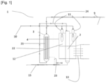
- Figure 2 is a schematic representation of an apparatus according to one embodiment.
- the apparatus 1 for producing cracked gas product comprising hydrogen by an endothermic cracking reaction of an ammonia feedstock stream comprising:
- the main reactor for example is extending through said firing chamber configured for the combustion of a fuel gas stream. There can be a plurality of said main reactor extending through said firing chamber.
- the apparatus comprises a firing chamber 2, said firing chamber comprising a combustion zone 12 in which a combustion of the fuel gas stream into a combustion reaction flue gas is performed.
- a fuel gas inlet 10 is configured for the inlet of the fuel gas in the firing chamber 2.
- the apparatus comprises a partially converted ammonia stream conduits 24 arranged to discharge the partially converted ammonia stream from the secondary reactor and feed the main reactor with the discharged partially converted ammonia stream.
- the secondary reactors 3 comprises a feed distribution header and a partially converted ammonia stream collection header.
- the secondary reactor 3 is filled with a secondary catalyst comprising nickel as a catalytically active material, in particular as a catalytically active material on a carrier, for example aluminum oxide (Al2O3).
- the secondary catalyst comprises above 20 to above 45 wt% of nickel, preferably above 35 wt% of nickel and/or a precious metal, such as a ruthenium, preferably above 1,5 wt% of ruthenium, as a catalytically active material, in particular as a catalytically active material on a carrier.
- Figure 3 is a schematic representation of the main reactor according to a first embodiment.
- the reactor 209 comprises an outer shell tube 204, said outer shell tube 204 being pressurized.
- the outer shell tube 204 comprises a reaction chamber A in which a catalytic conversion of the ammonia feedstock stream is realized, said catalytic conversion being a cracking reaction.
- the reaction chamber A comprises a layer of an active solid catalyst 205, here a dumped bed of an active catalyst, said catalyst being configured to promote the catalytic conversion of ammonia into a cracked gas product comprising hydrogen, here a cracking reaction, at a temperature comprised between 600°C and 900°C, preferably between 700°C and 800°C at a pressure of around 25 barA.
- the catalyst layer is for example a catalyst comprising nickel.
- the partially converted ammonia stream circulates in the active catalyst layer 205 where the cracking reaction occurs. This reaction is possible at a high temperature and heat 207, 206 is provided to the reaction chamber A.
- the outer shell tube 204 and more precisely the reaction chamber A, comprises here a heat exchange tube 208, said heat exchange tube 208 being part of the cracked gas conduit 23 and arranged inside the reaction chamber A so as to be in a heat exchange relationship with the catalyst layer 205 and the partially converted ammonia stream.
- the heat exchange tube 208 is a single heat exchange tube, made of a thermal conductive material, such as a metal alloy, for example alloy 600.
- the heat exchanger comprises at least two tubes made of said thermal conductive material.
- the reactor 209 is configured to, after entry into the reaction chamber A by the entry 201, make the partially converted ammonia stream flow through the catalyst layer 205 for the cracking reaction of at least part of the feedstock stream into said cracked gas product in the catalyst layer 205, and then make the cracked gas product flow through the heat exchange tube 208, said heat exchange tube 208 being arranged inside the reaction chamber A.
- the catalyst layer 205 is configured to be partially heated by an external heat 207 from an external heat source.
- the external heat source is for example an external firing or electrical heating.
- the partially converted ammonia stream is thus converted into said cracked product comprising hydrogen.
- the partially converted ammonia stream is heated and said heat is provided to the cracking reaction.
- the cracked gas is further heated.
- the hot gas cracked product flows through the cracked gas heat exchange tube 208, it transfers internally its heat 206 to the catalyst layer 205.
- the catalyst layer is heated by an external heat source 207, and by an internal heat source 206.
- the consumption of external heat 207 is thus reduced.
- the cracked gas product flows through the heat exchange tube 208 in a countercurrent manner.
- the shell tube comprises an outlet for the cracked gas product 203 arranged to release the cracked gas product from the main reactor.
- Figure 4 is a schematic representation of the main reactor for producing a according to a second embodiment.
- the outer shell tube comprises a partially converted ammonia stream tube entry 210, the tube entry 210 being configured to let the ammonia feedstock stream enter in the outer shell tube 204, and more precisely in a reaction chamber A'.
- the reactor 214 comprises an outer shell tube 211 comprising the reaction chamber A', said reaction chamber being configured to be heated.
- the reactor comprises an active catalyst layer 212 arranged in the reaction chamber A'.
- the catalyst layer 212 is arranged to promote a cracking reaction of the partially converted ammonia stream into said cracked gas product.
- the partially converted ammonia stream circulates in the catalyst layer 212 which promotes the cracking reaction at a temperature comprised between 600°C and 900°C at a pressure of 25 barA.
- the catalyst layer comprises here nickel as a catalytically active material.
- the reactor 214 comprises two heat exchange tubes 213, said heat exchange tubes being part of the cracked gas conduit 23 and arranged for performing heat exchanges between the cracked gas product and the cracking reaction in the reaction chamber A'.
- the heat exchange tubes 213 have a coiled shape, the coils being interlaced.
- the catalyst layer 212 is configured to be partially heated by an external heat 214 from an external heat source.
- the external heat source is for example an external firing or electrical heating.
- the partially converted ammonia stream is thus converted into said cracked gas product comprising hydrogen.
- the partially converted ammonia stream is heated and said heat is provided to the cracking reaction.
- the cracked gas is further heated.
- the hot cracked gas product flows through the cracked gas product circulation duct of the heat exchanger 213, it transfers internally its heat 215 to the catalyst layer 212.
- the catalyst layer is heated by an external heat source 214, and by an internal heat source 215.
- the consumption of external heat 215 is thus reduced.
- the cracked gas product flows through the heat exchange tubes 213 in a countercurrent manner.
Landscapes
- Chemical & Material Sciences (AREA)
- Organic Chemistry (AREA)
- Health & Medical Sciences (AREA)
- General Health & Medical Sciences (AREA)
- Engineering & Computer Science (AREA)
- Combustion & Propulsion (AREA)
- Inorganic Chemistry (AREA)
- Devices And Processes Conducted In The Presence Of Fluids And Solid Particles (AREA)
Priority Applications (2)
| Application Number | Priority Date | Filing Date | Title |
|---|---|---|---|
| EP23219360.7A EP4574751A1 (de) | 2023-12-21 | 2023-12-21 | Verfahren zur herstellung eines wasserstoff enthaltenden spaltgasprodukts |
| PCT/EP2024/079014 WO2025131369A1 (en) | 2023-12-21 | 2024-10-15 | Process for producing cracked gas product comprising hydrogen |
Applications Claiming Priority (1)
| Application Number | Priority Date | Filing Date | Title |
|---|---|---|---|
| EP23219360.7A EP4574751A1 (de) | 2023-12-21 | 2023-12-21 | Verfahren zur herstellung eines wasserstoff enthaltenden spaltgasprodukts |
Publications (1)
| Publication Number | Publication Date |
|---|---|
| EP4574751A1 true EP4574751A1 (de) | 2025-06-25 |
Family
ID=89308067
Family Applications (1)
| Application Number | Title | Priority Date | Filing Date |
|---|---|---|---|
| EP23219360.7A Pending EP4574751A1 (de) | 2023-12-21 | 2023-12-21 | Verfahren zur herstellung eines wasserstoff enthaltenden spaltgasprodukts |
Country Status (2)
| Country | Link |
|---|---|
| EP (1) | EP4574751A1 (de) |
| WO (1) | WO2025131369A1 (de) |
Citations (4)
| Publication number | Priority date | Publication date | Assignee | Title |
|---|---|---|---|---|
| US11084012B2 (en) * | 2019-06-20 | 2021-08-10 | National Engineering Research Center Of Chemical Fertilizer Catalyst, Fuzhou University | Ammonia decomposition apparatus and system and hydrogen production method |
| CN113896168A (zh) * | 2021-10-14 | 2022-01-07 | 西南化工研究设计院有限公司 | 一种两段法氨裂解制氢气或制还原气的方法 |
| WO2022265650A1 (en) * | 2021-06-18 | 2022-12-22 | Air Products And Chemicals, Inc. | Ammonia cracking process |
| EP4112540A1 (de) * | 2021-06-30 | 2023-01-04 | Linde GmbH | Verfahren und vorrichtung zur erzeugung von wasserstoff aus ammoniak |
-
2023
- 2023-12-21 EP EP23219360.7A patent/EP4574751A1/de active Pending
-
2024
- 2024-10-15 WO PCT/EP2024/079014 patent/WO2025131369A1/en active Pending
Patent Citations (4)
| Publication number | Priority date | Publication date | Assignee | Title |
|---|---|---|---|---|
| US11084012B2 (en) * | 2019-06-20 | 2021-08-10 | National Engineering Research Center Of Chemical Fertilizer Catalyst, Fuzhou University | Ammonia decomposition apparatus and system and hydrogen production method |
| WO2022265650A1 (en) * | 2021-06-18 | 2022-12-22 | Air Products And Chemicals, Inc. | Ammonia cracking process |
| EP4112540A1 (de) * | 2021-06-30 | 2023-01-04 | Linde GmbH | Verfahren und vorrichtung zur erzeugung von wasserstoff aus ammoniak |
| CN113896168A (zh) * | 2021-10-14 | 2022-01-07 | 西南化工研究设计院有限公司 | 一种两段法氨裂解制氢气或制还原气的方法 |
Also Published As
| Publication number | Publication date |
|---|---|
| WO2025131369A1 (en) | 2025-06-26 |
Similar Documents
| Publication | Publication Date | Title |
|---|---|---|
| JP4869696B2 (ja) | 小型円筒状改質装置 | |
| CA2706417C (en) | Improving efficiency of ammonia processes | |
| CA2442657C (en) | Process and apparatus for the preparation of synthesis gas | |
| CN112585086B (zh) | 烃类的蒸汽重整或干重整 | |
| EP3160632B1 (de) | Dampf-methanreformersystem und verfahren zur durchführung eines verfahrens zur dampf-methanreformierung | |
| US9725379B2 (en) | Method for reducing energy consumption in a process to produce styrene via dehydrogenation of ethylbenzene | |
| EP4574751A1 (de) | Verfahren zur herstellung eines wasserstoff enthaltenden spaltgasprodukts | |
| WO2001012310A1 (en) | Catalyst tubes for endothermic reaction especially for the production of hydrogen and syngas | |
| EP4389697A1 (de) | Verfahren zur herstellung eines wasserstoff enthaltenden synthesegasprodukts | |
| CN107921401B (zh) | 进行蒸汽重整和水煤气反应来生产氢气的交换器-反应器 | |
| EP4389693A1 (de) | Verfahren zur herstellung eines wasserstoff enthaltenden synthesegasprodukts | |
| EP3691991B1 (de) | Neues layout für zwischenbettkühlung bei schwefelsäureanlagen | |
| US10272406B2 (en) | Reactor and heater configuration synergies in paraffin dehydrogenation process | |
| CN216093567U (zh) | 一种丙烷脱氢装置新型反应系统 | |
| EP4691969A1 (de) | Verfahren zur herstellung eines wasserstoffprodukts | |
| CN217164326U (zh) | 一种丙烷脱氢反应一体化转化炉 | |
| WO2024149889A1 (en) | Ammonia cracking for hydrogen production | |
| KR20260004430A (ko) | 크래킹 가스로부터의 열 회수 방법 및 장치 | |
| CN120644133A (zh) | 一种粉煤加压气化装置co等温变换系统及工艺 | |
| EP4688243A1 (de) | Verfahren zur herstellung eines wasserstoff enthaltenden synthesegasprodukts | |
| WO2024227907A1 (en) | Ammonia cracking process with a recuperative heat exchange reactor |
Legal Events
| Date | Code | Title | Description |
|---|---|---|---|
| PUAI | Public reference made under article 153(3) epc to a published international application that has entered the european phase |
Free format text: ORIGINAL CODE: 0009012 |
|
| STAA | Information on the status of an ep patent application or granted ep patent |
Free format text: STATUS: THE APPLICATION HAS BEEN PUBLISHED |
|
| AK | Designated contracting states |
Kind code of ref document: A1 Designated state(s): AL AT BE BG CH CY CZ DE DK EE ES FI FR GB GR HR HU IE IS IT LI LT LU LV MC ME MK MT NL NO PL PT RO RS SE SI SK SM TR |