EP4574571A1 - Illuminated grille for a vehicle and related vehicle - Google Patents
Illuminated grille for a vehicle and related vehicle Download PDFInfo
- Publication number
- EP4574571A1 EP4574571A1 EP23219620.4A EP23219620A EP4574571A1 EP 4574571 A1 EP4574571 A1 EP 4574571A1 EP 23219620 A EP23219620 A EP 23219620A EP 4574571 A1 EP4574571 A1 EP 4574571A1
- Authority
- EP
- European Patent Office
- Prior art keywords
- grille
- vehicles according
- illuminated
- illuminated grille
- lighting
- Prior art date
- Legal status (The legal status is an assumption and is not a legal conclusion. Google has not performed a legal analysis and makes no representation as to the accuracy of the status listed.)
- Granted
Links
Images






Classifications
-
- B—PERFORMING OPERATIONS; TRANSPORTING
- B60—VEHICLES IN GENERAL
- B60Q—ARRANGEMENT OF SIGNALLING OR LIGHTING DEVICES, THE MOUNTING OR SUPPORTING THEREOF OR CIRCUITS THEREFOR, FOR VEHICLES IN GENERAL
- B60Q1/00—Arrangement of optical signalling or lighting devices, the mounting or supporting thereof or circuits therefor
- B60Q1/26—Arrangement of optical signalling or lighting devices, the mounting or supporting thereof or circuits therefor the devices being primarily intended to indicate the vehicle, or parts thereof, or to give signals, to other traffic
- B60Q1/2619—Arrangement of optical signalling or lighting devices, the mounting or supporting thereof or circuits therefor the devices being primarily intended to indicate the vehicle, or parts thereof, or to give signals, to other traffic built in the vehicle body
- B60Q1/2623—Details of the fastening means
- B60Q1/263—Snap-in fasteners
-
- B—PERFORMING OPERATIONS; TRANSPORTING
- B60—VEHICLES IN GENERAL
- B60Q—ARRANGEMENT OF SIGNALLING OR LIGHTING DEVICES, THE MOUNTING OR SUPPORTING THEREOF OR CIRCUITS THEREFOR, FOR VEHICLES IN GENERAL
- B60Q1/00—Arrangement of optical signalling or lighting devices, the mounting or supporting thereof or circuits therefor
- B60Q1/0088—Details of electrical connections
-
- B—PERFORMING OPERATIONS; TRANSPORTING
- B60—VEHICLES IN GENERAL
- B60Q—ARRANGEMENT OF SIGNALLING OR LIGHTING DEVICES, THE MOUNTING OR SUPPORTING THEREOF OR CIRCUITS THEREFOR, FOR VEHICLES IN GENERAL
- B60Q1/00—Arrangement of optical signalling or lighting devices, the mounting or supporting thereof or circuits therefor
- B60Q1/26—Arrangement of optical signalling or lighting devices, the mounting or supporting thereof or circuits therefor the devices being primarily intended to indicate the vehicle, or parts thereof, or to give signals, to other traffic
- B60Q1/2619—Arrangement of optical signalling or lighting devices, the mounting or supporting thereof or circuits therefor the devices being primarily intended to indicate the vehicle, or parts thereof, or to give signals, to other traffic built in the vehicle body
- B60Q1/2638—Positioning the device housing by indexing means separate from the fastening means, e.g. pins, rails
-
- B—PERFORMING OPERATIONS; TRANSPORTING
- B60—VEHICLES IN GENERAL
- B60Q—ARRANGEMENT OF SIGNALLING OR LIGHTING DEVICES, THE MOUNTING OR SUPPORTING THEREOF OR CIRCUITS THEREFOR, FOR VEHICLES IN GENERAL
- B60Q1/00—Arrangement of optical signalling or lighting devices, the mounting or supporting thereof or circuits therefor
- B60Q1/26—Arrangement of optical signalling or lighting devices, the mounting or supporting thereof or circuits therefor the devices being primarily intended to indicate the vehicle, or parts thereof, or to give signals, to other traffic
- B60Q1/2661—Arrangement of optical signalling or lighting devices, the mounting or supporting thereof or circuits therefor the devices being primarily intended to indicate the vehicle, or parts thereof, or to give signals, to other traffic mounted on parts having other functions
-
- B—PERFORMING OPERATIONS; TRANSPORTING
- B60—VEHICLES IN GENERAL
- B60Q—ARRANGEMENT OF SIGNALLING OR LIGHTING DEVICES, THE MOUNTING OR SUPPORTING THEREOF OR CIRCUITS THEREFOR, FOR VEHICLES IN GENERAL
- B60Q1/00—Arrangement of optical signalling or lighting devices, the mounting or supporting thereof or circuits therefor
- B60Q1/26—Arrangement of optical signalling or lighting devices, the mounting or supporting thereof or circuits therefor the devices being primarily intended to indicate the vehicle, or parts thereof, or to give signals, to other traffic
- B60Q1/28—Arrangement of optical signalling or lighting devices, the mounting or supporting thereof or circuits therefor the devices being primarily intended to indicate the vehicle, or parts thereof, or to give signals, to other traffic for indicating front of vehicle
-
- B—PERFORMING OPERATIONS; TRANSPORTING
- B60—VEHICLES IN GENERAL
- B60R—VEHICLES, VEHICLE FITTINGS, OR VEHICLE PARTS, NOT OTHERWISE PROVIDED FOR
- B60R19/00—Wheel guards; Radiator guards, e.g. grilles; Obstruction removers; Fittings damping bouncing force in collisions
- B60R19/52—Radiator or grille guards ; Radiator grilles
-
- F—MECHANICAL ENGINEERING; LIGHTING; HEATING; WEAPONS; BLASTING
- F21—LIGHTING
- F21S—NON-PORTABLE LIGHTING DEVICES; SYSTEMS THEREOF; VEHICLE LIGHTING DEVICES SPECIALLY ADAPTED FOR VEHICLE EXTERIORS
- F21S43/00—Signalling devices specially adapted for vehicle exteriors, e.g. brake lamps, direction indicator lights or reversing lights
- F21S43/10—Signalling devices specially adapted for vehicle exteriors, e.g. brake lamps, direction indicator lights or reversing lights characterised by the light source
- F21S43/13—Signalling devices specially adapted for vehicle exteriors, e.g. brake lamps, direction indicator lights or reversing lights characterised by the light source characterised by the type of light source
- F21S43/14—Light emitting diodes [LED]
-
- F—MECHANICAL ENGINEERING; LIGHTING; HEATING; WEAPONS; BLASTING
- F21—LIGHTING
- F21S—NON-PORTABLE LIGHTING DEVICES; SYSTEMS THEREOF; VEHICLE LIGHTING DEVICES SPECIALLY ADAPTED FOR VEHICLE EXTERIORS
- F21S43/00—Signalling devices specially adapted for vehicle exteriors, e.g. brake lamps, direction indicator lights or reversing lights
- F21S43/20—Signalling devices specially adapted for vehicle exteriors, e.g. brake lamps, direction indicator lights or reversing lights characterised by refractors, transparent cover plates, light guides or filters
- F21S43/265—Transparent cover plates, e.g. for protecting the interior of the signalling devices against environmental influences
-
- F—MECHANICAL ENGINEERING; LIGHTING; HEATING; WEAPONS; BLASTING
- F21—LIGHTING
- F21S—NON-PORTABLE LIGHTING DEVICES; SYSTEMS THEREOF; VEHICLE LIGHTING DEVICES SPECIALLY ADAPTED FOR VEHICLE EXTERIORS
- F21S43/00—Signalling devices specially adapted for vehicle exteriors, e.g. brake lamps, direction indicator lights or reversing lights
- F21S43/20—Signalling devices specially adapted for vehicle exteriors, e.g. brake lamps, direction indicator lights or reversing lights characterised by refractors, transparent cover plates, light guides or filters
- F21S43/27—Attachment thereof
-
- B—PERFORMING OPERATIONS; TRANSPORTING
- B60—VEHICLES IN GENERAL
- B60Q—ARRANGEMENT OF SIGNALLING OR LIGHTING DEVICES, THE MOUNTING OR SUPPORTING THEREOF OR CIRCUITS THEREFOR, FOR VEHICLES IN GENERAL
- B60Q2900/00—Features of lamps not covered by other groups in B60Q
- B60Q2900/40—Several lamps activated in sequence, e.g. sweep effect, progressive activation
-
- B—PERFORMING OPERATIONS; TRANSPORTING
- B60—VEHICLES IN GENERAL
- B60R—VEHICLES, VEHICLE FITTINGS, OR VEHICLE PARTS, NOT OTHERWISE PROVIDED FOR
- B60R19/00—Wheel guards; Radiator guards, e.g. grilles; Obstruction removers; Fittings damping bouncing force in collisions
- B60R19/52—Radiator or grille guards ; Radiator grilles
- B60R2019/525—Radiator grilles
-
- F—MECHANICAL ENGINEERING; LIGHTING; HEATING; WEAPONS; BLASTING
- F21—LIGHTING
- F21W—INDEXING SCHEME ASSOCIATED WITH SUBCLASSES F21K, F21L, F21S and F21V, RELATING TO USES OR APPLICATIONS OF LIGHTING DEVICES OR SYSTEMS
- F21W2104/00—Exterior vehicle lighting devices for decorative purposes
Definitions
- the present invention relates to an illuminated grille for a vehicle and to the related vehicle comprising said illuminated grille.
- Vehicles and in particular motor vehicles, are commonly provided with grilles, usually arranged at the front, between the headlights, concealing the presence of a radiator of the vehicle engine and which are often used to support the number plate and/or the brand name of the vehicle manufacturer.
- the grilles are perforated to allow air to pass so that it can carry out the heat exchange with the radiator crossed by the cooling liquid of the vehicle engine.
- the grille In order to maximize said heat exchange, the grille must be as open as possible and have a thin structure.
- front grilles have a significant impact on the front of the motor vehicle.
- the power supply means 24 comprise at least one power cable 40 and a power source (not shown).
- the power cable 40 is preferably fixed to the grille body 8 by means of hooks 44, e.g., snap-on hooks, of the reversible type.
- the power cables 40 are at least partially housed in conduits obtained on a rear wall of the grille body 8.
- the coupling portion 36 can be made in one piece with the peripheral wall 16 or it can be on the peripheral wall 16.
- the coupling portion 36 preferably comprises a pair of cantilevered protuberances 100.
- the coupling portion 36 comprises a pair of through holes 104.
- the coupling portion 36 comprises a shelf 99 projecting in a cantilever manner from the side of said protuberances 100.
- the coupling means 32 comprise two guide grooves 92 and two guide ribs 96 which make a reversible mechanical connection with the grille body 8, as will be described better below.
- the guide grooves 92 are preferably 'U' -shaped so as to delimit a seat with a bilateral constraint for said protuberances.
- the coupling means 32 also comprises a front clip 98.
- Said front clip 98 for example, has a through opening 99.
- the protuberances 100 are inserted in the guide grooves 92.
- the guide ribs 96 at least partially pass through the through holes 104 of the peripheral wall 16.
- the lighting portion 52 can include grooves or regular ridges, for example, such as those typical of technically defined cylindrical optics, to obtain an even more refined aesthetic appearance, or simply to obtain a different style.
- convex or concave lenticular structures can be provided, on the lighting portion 52, e.g., with a polygonal base, such as those typical of optics technically defined as pillow optics.
- the lighting portion 52 can include a reflecting colored or metallic coating 54.
- Said coating 54 can be obtained by means of a sequence of mutually overlapping layers 55.
- the lighting portion 52 can be made in one piece with the peripheral wall 16 or it can be on the peripheral wall 16.
- the light beam-permeable portion 48 is opposite to said coupling portion 36.
- the light beam-permeable portion 48 can have various shapes: for example, it can comprise an undercut 56 or generally a hole or slot.
- a peripheral edge of said undercut 56 is shaped in such a way as to delimit and shape the light beam incident therein.
- Said at least one lighting module 20 can have various configurations and dimensions: for example, the lighting module 20 comprises a casing 60 which houses the light source 28 and a screen 64 which covers the casing 60 and intercepts the light beam produced by said light source 28.
- Said screen 64 is preferably removably connected to the casing 60, by reversible connection means, such as snap-on tongues 68, for example.
- the grille body 8 can have various configurations and dimensions.
- the grille body 8 comprises an internal lattice structure 72, onto which the power supply means 24 and the lighting module 20 are fixed, and an outer cover 76 which covers the internal lattice structure 72.
- said outer cover 76 is provided with openings 80 at the windows 12 which are delimited by the internal lattice structure 72.
- said outer cover 76 at least partially delimits the peripheral wall 16 of the windows 12.
- the shelves 84 face the light source 28 and the light beam-permeable portion 48, so as to receive the light beam crossing said light beam-permeable portion 48.
- the light sources 28, the windows 12 and the lighting portions can have any spatial arrangement.
- the present invention allows overcoming the drawbacks presented in the prior art.
- the present invention overcomes the problem of customizing the illuminated grille for vehicles.
- the solution allows keeping the dimensions of the grille highly compact, ensuring the passage of air and the heat exchange with the radiator located behind the grille.
- the grille allows concealing the cables and light sources from the sight of outside observers.
Landscapes
- Engineering & Computer Science (AREA)
- Mechanical Engineering (AREA)
- General Engineering & Computer Science (AREA)
- Physics & Mathematics (AREA)
- Microelectronics & Electronic Packaging (AREA)
- Optics & Photonics (AREA)
- Arrangements Of Lighting Devices For Vehicle Interiors, Mounting And Supporting Thereof, Circuits Therefore (AREA)
Abstract
Description
- The present invention relates to an illuminated grille for a vehicle and to the related vehicle comprising said illuminated grille.
- Vehicles, and in particular motor vehicles, are commonly provided with grilles, usually arranged at the front, between the headlights, concealing the presence of a radiator of the vehicle engine and which are often used to support the number plate and/or the brand name of the vehicle manufacturer.
- The grilles are perforated to allow air to pass so that it can carry out the heat exchange with the radiator crossed by the cooling liquid of the vehicle engine.
- In order to maximize said heat exchange, the grille must be as open as possible and have a thin structure.
- In recent years, the need is increasingly felt to provide front grilles of motor vehicles not only having a technical function, but also an aesthetic function.
- In fact, front grilles have a significant impact on the front of the motor vehicle.
- Therefore, it is known to provide front grilles with lighting means mainly for aesthetic purposes.
- However, such known solutions are not free from drawbacks and limitations.
- In fact, as seen, the grilles must be as open as possible or perforated, thus provided with wide windows for the passage of air, and at the same time, they must have a thin frame.
- This means that there is little space available for fixing and/or housing lighting means, which must obviously be concealed from outside observers when not activated. It results that the solutions of the prior art do not allow particular grille customizations and/or lightings and are also very costly to manufacture.
- The need is thus felt to solve the drawbacks and limitations mentioned with reference to the prior art.
- Such a need is met by an illuminated grille according to claim 1 and a vehicle according to claim 22.
- Further features and advantages of the present invention will become more comprehensible from the following description of preferred, non-limiting embodiments thereof, in which:
-
Figure 1 shows a perspective diagrammatic view, in an exploded configuration, of an illuminated grille according to a possible embodiment of the present invention; -
figures 2-3 show perspective views, from different angles and in an assembled configuration, of the illuminated grille infigure 1 ; -
figures 4-7 show various diagrammatic perspective or section views of lighting modules of an illuminated grille according to possible embodiments of the present invention; -
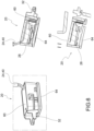
figures 8-9 show assembly details of the lighting modules on a grille body according to possible embodiments of the present invention; -
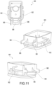
figures 10-11 show diagrammatic plan and perspective views, from different angles, of a lighting module casing according to embodiments of the present invention; -
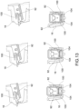
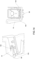
figures 12-14 show diagrammatic perspective and plan views of a snap insertion sequence of a lighting module on a peripheral grille body wall according to an embodiment of the present invention; -
figure 15 shows a diagrammatic perspective view of a grille portion according to a constructional variant of the present invention; -
figure 16 shows the enlarged detail XVI indicated infigure 15 . - The elements or parts of elements common to the embodiments described below will be indicated by the same reference numerals.
- With reference to the aforesaid figures,
reference numeral 4 indicates, as a whole, an overall diagrammatic view of an illuminated grille for vehicles. - For the purposes of the present invention, it does not show the type and/or position of the grille, which can commonly be at the front and outside, however it can also be positioned in other points of the vehicle, e.g., outside, at the back, or inside.
- Moreover, for the purposes of the present invention, it does not show the type of vehicle, which can comprise motor vehicles, motorcycles, cycles, industrial vehicles of any size and any power or propulsion.
- The illuminated
grille 4 for vehicles comprises a grille body 8 provided with a plurality of windows 12 delimited by respectiveperipheral walls 16, which are interconnected so as to form a lattice. - Advantageously, at at least one window 12, the
illuminated grille 4 comprises at least onelighting module 20. - In particular, said
lighting module 20 comprises power supply means 24, at least onelight source 28, powered by said power supply means 24, coupling means 32 for removably fixing thelighting module 20 to acoupling portion 36 of theperipheral wall 16. - The power supply means 24 comprise at least one
power cable 40 and a power source (not shown). Thepower cable 40 is preferably fixed to the grille body 8 by means ofhooks 44, e.g., snap-on hooks, of the reversible type. - According to a possible embodiment, the
power cables 40 are at least partially housed in conduits obtained on a rear wall of the grille body 8. - The
coupling portion 36 can be made in one piece with theperipheral wall 16 or it can be on theperipheral wall 16. - The
coupling portion 36 preferably comprises a pair ofcantilevered protuberances 100. - According to a possible embodiment, the
coupling portion 36 comprises a pair of throughholes 104. - According to a possible embodiment, the
coupling portion 36 comprises ashelf 99 projecting in a cantilever manner from the side of saidprotuberances 100. - According to a possible embodiment, the coupling means 32 comprise two
guide grooves 92 and twoguide ribs 96 which make a reversible mechanical connection with the grille body 8, as will be described better below. - The
guide grooves 92 are preferably 'U' -shaped so as to delimit a seat with a bilateral constraint for said protuberances. - According to an embodiment, the coupling means 32 also comprises a
front clip 98. Saidfront clip 98, for example, has a through opening 99. - The coupling between the
lighting module 20 and theperipheral wall 16 will now be described, with particular reference to the sequence illustrated infigures 12-14 . - In particular, it starts with the alignment between the
guide grooves 92 of thelighting module 20 and theprotuberances 100 of the peripheral wall 16 (figure 12 ). - Continuing the step of insertion, the
protuberances 100 are inserted in theguide grooves 92. - Moreover (
figure 13 ), the guide ribs 96 at least partially pass through the throughholes 104 of theperipheral wall 16. - The insertion of the guide ribs 96 through the through
holes 104 of theperipheral wall 16 is a further locking and security in the fixing of thelighting module 20. - Finally (
figure 14 ), when theprotuberances 100 are all the way down inside theguide grooves 92, thefront clip 98 at least partially engages theshelf 99. - The
peripheral wall 16 comprises at least one light beam-permeable portion 48, positioned facing saidlight source 28 so as to be crossed, at least partially, by the light beam produced by the light source 18. - In particular, after crossing the light beam-permeable portion 48, said light beam 48 impacts on a
lighting portion 52 of theperipheral wall 16, facing saidlight source 28 and said light beam-permeable portion 48. - In the example in
figures 15-16 , thelighting portion 52 can be provided with an embossing, or a satin finish, or a similar surface treatment 53, in which different types of patterns can be formed to obtain a shaded effect. For example, a central part of thelighting portion 52 can have a greater roughness than the peripheral parts of thesame lighting portion 52. Thus, the shaded effect can be obtained with a grain, which becomes increasingly "finer" gradually moving from the center to the periphery of thelighting portion 52. - Moreover, in combination with the embossing, or irrespective thereof, the
lighting portion 52 can include grooves or regular ridges, for example, such as those typical of technically defined cylindrical optics, to obtain an even more refined aesthetic appearance, or simply to obtain a different style. As an alternative to, or in combination with the grooves, or ridges, convex or concave lenticular structures can be provided, on thelighting portion 52, e.g., with a polygonal base, such as those typical of optics technically defined as pillow optics. - In a further possible constructional variant, not shown, the
lighting portion 52 can include a reflecting colored or metallic coating 54. Said coating 54 can be obtained by means of a sequence of mutually overlappinglayers 55. - The
lighting portion 52 can be made in one piece with theperipheral wall 16 or it can be on theperipheral wall 16. - According to a possible embodiment, the light beam-permeable portion 48 is opposite to said
coupling portion 36. - The light beam-permeable portion 48 can have various shapes: for example, it can comprise an undercut 56 or generally a hole or slot.
- According to a possible embodiment, a peripheral edge of said undercut 56 is shaped in such a way as to delimit and shape the light beam incident therein.
- Said at least one
lighting module 20 can have various configurations and dimensions: for example, thelighting module 20 comprises acasing 60 which houses thelight source 28 and ascreen 64 which covers thecasing 60 and intercepts the light beam produced by saidlight source 28. - Said
screen 64 is preferably removably connected to thecasing 60, by reversible connection means, such as snap-ontongues 68, for example. - The grille body 8 can have various configurations and dimensions.
- For example, the grille body 8 comprises an
internal lattice structure 72, onto which the power supply means 24 and thelighting module 20 are fixed, and anouter cover 76 which covers theinternal lattice structure 72. - In particular, said
outer cover 76 is provided withopenings 80 at the windows 12 which are delimited by theinternal lattice structure 72. - Therefore, in the assembly configuration, said
outer cover 76 at least partially delimits theperipheral wall 16 of the windows 12. - According to a possible embodiment, the
outer cover 76 comprises, on an inner side facing theinternal lattice structure 72, a plurality of shelves 84 projecting towards theinternal lattice structure 72 so as to obtain saidlighting portions 52. - In other words, the shelves 84 face the
light source 28 and the light beam-permeable portion 48, so as to receive the light beam crossing said light beam-permeable portion 48. - Obviously, the
light sources 28, the windows 12 and the lighting portions can have any spatial arrangement. - Moreover, it is also possible to provide an overtime-dynamic power supply of the various
light sources 28 provided on the grille body 8, so as to create animation effects. - As can be appreciated from the description above, the present invention allows overcoming the drawbacks presented in the prior art.
- In particular, the present invention overcomes the problem of customizing the illuminated grille for vehicles.
- In fact, it is possible to manufacture an illuminated grille having any light pattern, both of the fixed type and of the varying type (animation). More specifically, each lighting module can arbitrarily be oriented towards a respective lighting portion of the peripheral wall, thus generating, in use, the formation of imaginative decorative light patterns on the illuminated grille which can be controlled by a control unit, not shown, according to a well-established animation sequence.
- Moreover, the solution is particularly cost-effective to manufacture.
- Moreover, the solution allows keeping the dimensions of the grille highly compact, ensuring the passage of air and the heat exchange with the radiator located behind the grille. At the same time, the grille allows concealing the cables and light sources from the sight of outside observers.
- Moreover, the cables are neatly arranged at least partially inside the grille structure, unlike the solutions of the prior art.
- Moreover, the fixing of the lighting modules onto the peripheral wall is particularly stable and safe even when the vehicle is moving, despite the considerable mechanical stresses and vibrations to which the grille is subjected.
- In order to meet specific contingent needs, those skilled in the art may make several changes and variations to the solutions described above.
- The scope of protection of the invention is defined by the following claims.
-
- 4: illuminated grille
- 8: grille body
- 12: window
- 16: peripheral wall
- 20: lighting module
- 24: power supply means
- 28: light source
- 32: coupling means
- 36: coupling portion
- 40: power cable
- 44: hooks
- 48: permeable light beam portion
- 52: lighting portion
- 53: surface treatment
- 54: coating
- 55: layers
- 56: undercut
- 60: casing
- 64: screen
- 68: snap-on tongue
- 72: internal lattice structure
- 76: outer cover
- 80: openings
- 84: shelf
- 92: guide groove
- 96: guide rib
- 98: front clip
- 99: shelf
- 100: protuberances
- 104: through holes
Claims (22)
- An illuminated grille (4) for vehicles, comprising- a grille body (8) provided with a plurality of windows (12) delimited by respective peripheral walls (16) interconnected so as to form a lattice,- wherein at at least one window (12), the grille body (8) comprises at least one lighting module (20),- said lighting module (20) comprising power supply means (24), at least one light source (28), powered by said power supply means (24), coupling means (32) for fixing the lighting module (20) to a coupling portion (36) of the peripheral wall (16),- said coupling means (32) orienting said lighting module (20), so that a lighting portion (52) of the peripheral wall (16) faces said at least one light source (28) of the lighting module, to be crossed by a light beam emitted by said at least one light source (28).
- An illuminated grille (4) for vehicles according to claim 1, wherein the peripheral wall (16) comprises at least one light beam-permeable portion (48), positioned facing said at least one lighting source (28) so as to be crossed, at least partially, by the light beam produced by the at least one light source (28), said light beam impacting said lighting portion (52) of the peripheral wall (16), facing said at least one light source (28) and said light beam-permeable portion (48).
- An illuminated grille (4) for vehicles according to claim 2, wherein said light beam-permeable portion (48) is opposite to said coupling portion (36).
- An illuminated grille (4) for vehicles according to claim 2 or 3, wherein said light beam-permeable portion (48) comprises an undercut and/or a hole and/or a slot.
- An illuminated grille (4) for vehicles according to claim 4, wherein a peripheral edge of said undercut (56) and/or a hole and/or a slot is shaped to delimit and shape the light beam incident therein.
- An illuminated grille (4) for vehicles according to claim 1, 2, 3, 4 or 5, wherein the power supply means (24) comprise power cables (40) at least partially housed in conduits obtained on a rear wall of the grille body (8) .
- An illuminated grille (4) for vehicles according to any one of claims 1 to 6, wherein the coupling means (32) are configured to make a reversible mechanical connection with the coupling portion (36) of the peripheral wall (16) of the grille body (8).
- An illuminated grille (4) for vehicles according to claim 7, wherein the coupling portion (36) comprises a pair of cantilevered protuberances (100), projecting towards the coupling means (32).
- An illuminated grille (4) for vehicles according to claim 8, wherein the coupling means (32) comprise two guide grooves (92) configured to make a guide and shape coupling with said protuberances (100).
- An illuminated grille (4) for vehicles according to claim 9, wherein the guide grooves (92) are 'U' shaped so as to delimit a seat with a bilateral constraint for said protuberances (100).
- An illuminated grille (4) for vehicles according to any one of claims 7 to 10, wherein the coupling portion (36) of the peripheral wall (16) comprises a pair of through holes (104).
- An illuminated grille (4) for vehicles according to claim 11, wherein the coupling means (32) comprise two guide ribs (96) configured to make a reversible mechanical connection with said through holes(104) of the peripheral wall (16).
- An illuminated grille (4) for vehicles according to any one of claims 7 to 12, wherein the coupling portion (36) comprises a shelf (99) projecting in a cantilever manner towards the associable lighting module (20).
- An illuminated grille (4) for vehicles according to claim 13, wherein the coupling means (32) also comprise a front clip (98) provided with a through opening (99), adapted to make a shape coupling with said shelf (99).
- An illuminated grille (4) according to any one of claims 1 to 14, wherein said at least one lighting module (20) comprises a casing (60) which houses the light source (28) and a screen (64) which covers the casing (60) and intercepts the light beam produced by said light source (28).
- An illuminated grille (4) for vehicles according to claim 15, wherein said screen (64) is removably connected to the casing (60), by reversible connection means, such as snap-on tongues (68).
- An illuminated grille (4) for vehicles according to any one of claims 1 to 16, wherein said grille body (8) comprises an internal lattice structure (72) onto which the power supply means (24) and the lighting module (20) are fixed, and an outer cover (76) which covers the internal lattice structure (72), said outer cover (76) being provided with openings (80) at the windows (12) delimited by the internal lattice structure (72).
- An illuminated grille (4) for vehicles according to claim 17, wherein in the assembly configuration, said outer cover (76) delimits, at least partially, the peripheral wall (16) of the windows (12).
- An illuminated grille (4) for vehicles according to claim 17 or 18, wherein the outer cover (76) comprises, on an inner side facing the internal lattice structure (72), a plurality of shelves (84) projecting towards the internal lattice structure (72), so as to obtain said lighting portions (52).
- An illuminated grille (4) for vehicles according to any one of claims 1 to 19, wherein said coupling means (32) are configured to removably fix the lighting module (20) to said coupling portion (36) of the peripheral wall (16) .
- An illuminated grille (4) for vehicles according to any one of claims 1 to 20, wherein the lighting portion (52) is provided with an embossing, or a satin finish, or a similar surface treatment (53), which is uniform or varies along the extension of the lighting portion (52).
- A vehicle comprising an illuminated grille according to any one of claims 1 to 21.
Priority Applications (1)
| Application Number | Priority Date | Filing Date | Title |
|---|---|---|---|
| EP23219620.4A EP4574571B1 (en) | 2023-12-22 | 2023-12-22 | Illuminated grille for a vehicle and related vehicle |
Applications Claiming Priority (1)
| Application Number | Priority Date | Filing Date | Title |
|---|---|---|---|
| EP23219620.4A EP4574571B1 (en) | 2023-12-22 | 2023-12-22 | Illuminated grille for a vehicle and related vehicle |
Publications (2)
| Publication Number | Publication Date |
|---|---|
| EP4574571A1 true EP4574571A1 (en) | 2025-06-25 |
| EP4574571B1 EP4574571B1 (en) | 2026-05-06 |
Family
ID=89854659
Family Applications (1)
| Application Number | Title | Priority Date | Filing Date |
|---|---|---|---|
| EP23219620.4A Active EP4574571B1 (en) | 2023-12-22 | 2023-12-22 | Illuminated grille for a vehicle and related vehicle |
Country Status (1)
| Country | Link |
|---|---|
| EP (1) | EP4574571B1 (en) |
Citations (7)
| Publication number | Priority date | Publication date | Assignee | Title |
|---|---|---|---|---|
| DE102009024783A1 (en) * | 2009-06-10 | 2010-12-16 | Daimler Ag | Fastening arrangement of a lighting unit on a trim part |
| EP3138734A1 (en) * | 2015-09-03 | 2017-03-08 | SMR Patents S.à.r.l. | Light module, light assembly and rear view device for a vehicle |
| CN207599577U (en) * | 2017-12-25 | 2018-07-10 | 江苏三明航空电器有限公司 | A kind of automobile front beam grid with energy saving luminous |
| WO2020006015A1 (en) * | 2018-06-26 | 2020-01-02 | Lacks Enterprises, Inc. | Textured coherent reflection component |
| CN112124239A (en) * | 2020-09-11 | 2020-12-25 | 宁波信泰机械有限公司 | Waterfall flowing water type light-emitting grid |
| US20210023982A1 (en) * | 2018-05-09 | 2021-01-28 | Bayerische Motoren Werke Aktiengesellschaft | Trim Element for a Motor Vehicle Front End Having an Illumination Device |
| KR20230099339A (en) * | 2021-12-27 | 2023-07-04 | 현대모비스 주식회사 | Grill lighting device and method for communication of vehicle |
-
2023
- 2023-12-22 EP EP23219620.4A patent/EP4574571B1/en active Active
Patent Citations (7)
| Publication number | Priority date | Publication date | Assignee | Title |
|---|---|---|---|---|
| DE102009024783A1 (en) * | 2009-06-10 | 2010-12-16 | Daimler Ag | Fastening arrangement of a lighting unit on a trim part |
| EP3138734A1 (en) * | 2015-09-03 | 2017-03-08 | SMR Patents S.à.r.l. | Light module, light assembly and rear view device for a vehicle |
| CN207599577U (en) * | 2017-12-25 | 2018-07-10 | 江苏三明航空电器有限公司 | A kind of automobile front beam grid with energy saving luminous |
| US20210023982A1 (en) * | 2018-05-09 | 2021-01-28 | Bayerische Motoren Werke Aktiengesellschaft | Trim Element for a Motor Vehicle Front End Having an Illumination Device |
| WO2020006015A1 (en) * | 2018-06-26 | 2020-01-02 | Lacks Enterprises, Inc. | Textured coherent reflection component |
| CN112124239A (en) * | 2020-09-11 | 2020-12-25 | 宁波信泰机械有限公司 | Waterfall flowing water type light-emitting grid |
| KR20230099339A (en) * | 2021-12-27 | 2023-07-04 | 현대모비스 주식회사 | Grill lighting device and method for communication of vehicle |
Also Published As
| Publication number | Publication date |
|---|---|
| EP4574571B1 (en) | 2026-05-06 |
Similar Documents
| Publication | Publication Date | Title |
|---|---|---|
| EP2353937B1 (en) | Vehicle lamp | |
| US20160288700A1 (en) | Concealed luminous automobile radiator cover | |
| JP6590935B2 (en) | Light assembly for illuminating the emblem | |
| EP3529107B1 (en) | Radiator grille of a motor vehicle | |
| US6158869A (en) | Puddle and footwell lighting integrated into a speaker grille | |
| EP3783259B1 (en) | Illumination device for a vehicle | |
| JP5522756B2 (en) | Lighting information unit | |
| JP2004207240A (en) | Headlamp type display device or lighting device for automobile | |
| US20110210842A1 (en) | Multi-signal device for vehicle, comprising a light-emitting core | |
| US7739818B2 (en) | Illuminated sign insert | |
| EP4574571A1 (en) | Illuminated grille for a vehicle and related vehicle | |
| US12427923B2 (en) | Exterior mirror for a vehicle, retaining system for use with a functional component of a vehicle | |
| JPH0685281B2 (en) | Lamp integrated front grill | |
| JP6575204B2 (en) | Light emitting device for vehicle | |
| CN217623336U (en) | Lighting decoration ring | |
| JP2011163686A (en) | Air conditioner | |
| US20150070879A1 (en) | Showcase Member With Direct-Mounted Led Light Source | |
| US20180320887A1 (en) | Illuminated mirror | |
| EP3618665B1 (en) | Illuminated mirror | |
| JP7666892B2 (en) | BSM unit | |
| JP4666174B2 (en) | Vehicle lighting | |
| JP7044023B2 (en) | Light emitting device | |
| CN217302613U (en) | Lighting lamp | |
| WO2003091070A1 (en) | Outside rear-view mirror for motor vehicles | |
| JP2009087787A (en) | Inner lens mounting method for compound vehicle lamp |
Legal Events
| Date | Code | Title | Description |
|---|---|---|---|
| PUAI | Public reference made under article 153(3) epc to a published international application that has entered the european phase |
Free format text: ORIGINAL CODE: 0009012 |
|
| STAA | Information on the status of an ep patent application or granted ep patent |
Free format text: STATUS: THE APPLICATION HAS BEEN PUBLISHED |
|
| AK | Designated contracting states |
Kind code of ref document: A1 Designated state(s): AL AT BE BG CH CY CZ DE DK EE ES FI FR GB GR HR HU IE IS IT LI LT LU LV MC ME MK MT NL NO PL PT RO RS SE SI SK SM TR |
|
| STAA | Information on the status of an ep patent application or granted ep patent |
Free format text: STATUS: REQUEST FOR EXAMINATION WAS MADE |
|
| GRAP | Despatch of communication of intention to grant a patent |
Free format text: ORIGINAL CODE: EPIDOSNIGR1 |
|
| STAA | Information on the status of an ep patent application or granted ep patent |
Free format text: STATUS: GRANT OF PATENT IS INTENDED |
|
| 17P | Request for examination filed |
Effective date: 20251215 |
|
| GRAJ | Information related to disapproval of communication of intention to grant by the applicant or resumption of examination proceedings by the epo deleted |
Free format text: ORIGINAL CODE: EPIDOSDIGR1 |
|
| STAA | Information on the status of an ep patent application or granted ep patent |
Free format text: STATUS: REQUEST FOR EXAMINATION WAS MADE |
|
| RIC1 | Information provided on ipc code assigned before grant |
Ipc: B60Q 1/26 20060101AFI20251222BHEP Ipc: B60Q 1/28 20060101ALI20251222BHEP Ipc: B60R 19/52 20060101ALI20251222BHEP Ipc: F21S 43/14 20180101ALI20251222BHEP Ipc: F21S 43/20 20180101ALI20251222BHEP Ipc: F21S 43/27 20180101ALI20251222BHEP Ipc: B60Q 1/00 20060101ALI20251222BHEP Ipc: F21W 104/00 20180101ALN20251222BHEP |
|
| GRAP | Despatch of communication of intention to grant a patent |
Free format text: ORIGINAL CODE: EPIDOSNIGR1 |
|
| STAA | Information on the status of an ep patent application or granted ep patent |
Free format text: STATUS: GRANT OF PATENT IS INTENDED |
|
| INTG | Intention to grant announced |
Effective date: 20260119 |
|
| INTC | Intention to grant announced (deleted) | ||
| RIC1 | Information provided on ipc code assigned before grant |
Ipc: B60Q 1/26 20060101AFI20260126BHEP Ipc: B60Q 1/28 20060101ALI20260126BHEP Ipc: B60R 19/52 20060101ALI20260126BHEP Ipc: F21S 43/14 20180101ALI20260126BHEP Ipc: F21S 43/20 20180101ALI20260126BHEP Ipc: F21S 43/27 20180101ALI20260126BHEP Ipc: B60Q 1/00 20060101ALI20260126BHEP Ipc: F21W 104/00 20180101ALN20260126BHEP |
|
| INTG | Intention to grant announced |
Effective date: 20260209 |
|
| GRAS | Grant fee paid |
Free format text: ORIGINAL CODE: EPIDOSNIGR3 |
|
| GRAA | (expected) grant |
Free format text: ORIGINAL CODE: 0009210 |
|
| STAA | Information on the status of an ep patent application or granted ep patent |
Free format text: STATUS: THE PATENT HAS BEEN GRANTED |