EP4574370A1 - Cutting unit, machine tool, and method for machining panels - Google Patents
Cutting unit, machine tool, and method for machining panels Download PDFInfo
- Publication number
- EP4574370A1 EP4574370A1 EP24219333.2A EP24219333A EP4574370A1 EP 4574370 A1 EP4574370 A1 EP 4574370A1 EP 24219333 A EP24219333 A EP 24219333A EP 4574370 A1 EP4574370 A1 EP 4574370A1
- Authority
- EP
- European Patent Office
- Prior art keywords
- panels
- panel
- pack
- cutting unit
- space
- Prior art date
- Legal status (The legal status is an assumption and is not a legal conclusion. Google has not performed a legal analysis and makes no representation as to the accuracy of the status listed.)
- Granted
Links
Images



Classifications
-
- B—PERFORMING OPERATIONS; TRANSPORTING
- B27—WORKING OR PRESERVING WOOD OR SIMILAR MATERIAL; NAILING OR STAPLING MACHINES IN GENERAL
- B27M—WORKING OF WOOD NOT PROVIDED FOR IN SUBCLASSES B27B - B27L; MANUFACTURE OF SPECIFIC WOODEN ARTICLES
- B27M1/00—Working of wood not provided for in subclasses B27B - B27L, e.g. by stretching
- B27M1/08—Working of wood not provided for in subclasses B27B - B27L, e.g. by stretching by multi-step processes
-
- B—PERFORMING OPERATIONS; TRANSPORTING
- B23—MACHINE TOOLS; METAL-WORKING NOT OTHERWISE PROVIDED FOR
- B23D—PLANING; SLOTTING; SHEARING; BROACHING; SAWING; FILING; SCRAPING; LIKE OPERATIONS FOR WORKING METAL BY REMOVING MATERIAL, NOT OTHERWISE PROVIDED FOR
- B23D59/00—Accessories specially designed for sawing machines or sawing devices
- B23D59/001—Measuring or control devices, e.g. for automatic control of work feed pressure on band saw blade
-
- B—PERFORMING OPERATIONS; TRANSPORTING
- B27—WORKING OR PRESERVING WOOD OR SIMILAR MATERIAL; NAILING OR STAPLING MACHINES IN GENERAL
- B27B—SAWS FOR WOOD OR SIMILAR MATERIAL; COMPONENTS OR ACCESSORIES THEREFOR
- B27B5/00—Sawing machines working with circular or cylindrical saw blades; Components or equipment therefor
- B27B5/02—Sawing machines working with circular or cylindrical saw blades; Components or equipment therefor characterised by a special purpose only
- B27B5/06—Sawing machines working with circular or cylindrical saw blades; Components or equipment therefor characterised by a special purpose only for dividing plates in parts of determined size, e.g. panels
- B27B5/065—Sawing machines working with circular or cylindrical saw blades; Components or equipment therefor characterised by a special purpose only for dividing plates in parts of determined size, e.g. panels with feedable saw blades, e.g. arranged on a carriage
-
- B—PERFORMING OPERATIONS; TRANSPORTING
- B27—WORKING OR PRESERVING WOOD OR SIMILAR MATERIAL; NAILING OR STAPLING MACHINES IN GENERAL
- B27G—ACCESSORY MACHINES OR APPARATUS FOR WORKING WOOD OR SIMILAR MATERIALS; TOOLS FOR WORKING WOOD OR SIMILAR MATERIALS; SAFETY DEVICES FOR WOOD WORKING MACHINES OR TOOLS
- B27G19/00—Safety guards or devices specially adapted for wood saws; Auxiliary devices facilitating proper operation of wood saws
- B27G19/08—Accessories for keeping open the saw kerf, e.g. riving knives or wedge plates
Definitions
- the present invention concerns a cutting unit for a machine tool.
- the present invention also concerns a machine tool and a method for machining panels.
- Nesting processing means a type of machining in which pieces of different shapes and sizes are obtained from a single panel, reducing waste parts to a minimum, using a tool, such as a disc or shaped blade, cylindrical cutters or shaped, and the like.
- machining centers for nesting have a base, a support surface of at least one panel, generally in aluminum or Bakelite, arranged on the base, a movable crosspiece along the base, generally positioned above the surface, which can be mobile or fixed with respect to the support surface.
- the crosshead supports one or more machining heads.
- Each machining head is movable along at least one axis.
- each machining head is equipped with a spindle, coupled, in use, to a tool holder, which can in turn be coupled to a specific tool depending on the type of machining to be performed.
- the machining tool is usually a cutter, for example, an end mill, capable of drilling the panel and cutting out the required parts.
- the end mill is moved following a cutting pattern, designed to maximize the use of the panel, reducing waste to a minimum.
- Machine tools called panel saws are also known, designed to cut panels according to a cutting direction.
- a panel sawing machine comprises a first loading/unloading station for a piece or a pack of pieces, a machining station and a second exit/entry or loading/unloading station, usually provided with a surface, from which the machined pieces they are loaded or picked up by an operator or a mechanical arm.
- the pieces are usually moved from the first loading station towards the processing station by means of a handling member commonly identified as a "pusher" group, which comprises a system of clamps designed to clamp the rear portion of the panel with respect to the feeding direction.
- a handling member commonly identified as a "pusher” group, which comprises a system of clamps designed to clamp the rear portion of the panel with respect to the feeding direction.
- This system of grippers is supported above the workpiece support surface by a support structure, which is movable along the feeding direction by means of actuator means.
- the pieces are cut using a cutting unit that slides along a cutting direction, generally transverse to the plane on which the panels are fed. Following the cutting, the pieces are then unloaded in the first or second loading/unloading station, to be picked up or reintroduced into the machine for subsequent processing.
- the cutting unit comprises a cutting blade, rotating in a first direction, preceded by an engraving blade, rotating in the direction opposite to the first direction of the cutting blade.
- the engraving blade generally has a smaller diameter than the cutting blade and a slightly greater thickness, of a few tenths of a millimeter, and is designed to realize an incision only on the surface of the face of the panel from which the teeth are expected to emerge of the cutting blade, so as not to create chips protruding from the surface.
- a video camera is associated with the cutting unit, to capture the lower part of the panel after sectioning.
- the images provided by the camera allow checking whether the scoring blade is aligned with the cutting blade. In the event that the two blades are not aligned, a control system adjusts the cutting blade.
- the technical problem, posed and solved by the present invention is that of providing a cutting unit that allows the above-mentioned drawbacks relating to the prior art to be overcome.
- One purpose of the invention is to control the surface quality of the side of the panel where the cut was made.
- a further purpose of the invention is to check the surface of different panels after the cutting operation.
- Yet another aim of the invention is to check the surface of a panel both after a cutting operation and after a nesting process.
- a machine tool having the features defined in claim 12.
- a method for machining panels includes the features defined in claim 15.
- the present invention provides some significant advantages.
- the detection element allows capturing images of the entire surface involved in the cut.
- the image acquisition device is integral with the mobile support, on which the cutting tool is mounted, so as to move, following the cut and acquire the images following the cutting operation.
- the acquisition device is operationally connected to a control unit. This allows to immediately checking the quality of the cut and stop processing if the quality is not satisfactory.
- Figure 1 shows a cutting machine of a known type.
- the cutting machine M essentially comprises an input station S1, used for loading/unloading the panel P, at least a processing station S2 to carry out a respective machining on one or more panels P, a station output S3, used for unloading/loading panel P, and a logical control unit, in which pre-established cutting patterns are stored.
- Said output station S3 can also be used as a loading station for the panels to be reinserted into the cutting machine M to perform further cuts.
- the panels P that has to be subjected to machining are arranged on a support surface of said loading station S1 and advance on said support surface along a direction of advancement X, until they reach the processing station S2, through the exerted by one or more handling groups, such as pushers, each of which can include one or more gripping and pushing elements, such as for example grippers for gripping and moving the panel P to be processed.
- handling groups such as pushers, each of which can include one or more gripping and pushing elements, such as for example grippers for gripping and moving the panel P to be processed.
- the processing station S2 comprises a cutting unit and a work surface, on which the panel P to be cut is placed.
- the cutting unit comprises a carriage movable along a processing direction Y, which is in turn orthogonal to said advancement direction X, in a longitudinal chamber formed under said work surface.
- movement means are also provided to move said carriage along said processing direction, in both directions of travel.
- the cutting tool is mounted on said carriage, in particular a circular blade, which slides along said processing direction, performing forward and backward strokes.
- Said circular blade lies on a Y-Z plane, defined by said Y processing direction and by a Z development direction, orthogonal to said X advancement direction and Y machining direction.
- a longitudinal slot is obtained in the same work surface, which extends along said Y processing direction.
- a blocking means such as a pressure member, which extends along said processing direction Y and is movable along said development direction Z, between a raised rest position and a lowered working position, so such as to allow the blocking of the panel P to be worked between the work surface and the pressure member itself.
- Said circular blade is able to cross said longitudinal slot, protruding from said work surface for a given portion, so as to cut the panel P along a cutting line L, parallel to said processing direction Y.
- the blade makes a cut such as to separate at least a first portion P1 of said panel or pack of panels P from the remaining part P2 of the panel or pack of panels P, creating a space S between said first portion P1 and the remaining part P2 of the panel or the pack of panels P, as illustrated in figure 2 .
- Said circular blade is also rotatable around a rotation axis, orthogonal to the aforementioned Y-Z plane and therefore parallel to said direction of advancement X.
- Figures 4 and 5 show a panel saw M, on which a cutting unit 1 is installed in a first embodiment of the present invention.
- the cutting unit 1 comprises a support 2; at least one cutting tool 3 associated with said support 2 and capable of making at least one cut on at least one panel or a pack of panels P, so as to separate at least a first portion P1 of said panel or pack of panels P from the remaining part P2 of the panel or pack of panels P, creating a space S between said first portion P1 and the remaining part P2 of the panel or pack of panels P, said support 2 and said panel or pack of panels P being movable with respect to each other, and a device 4 for image acquisition capable of being associated with said support 2.
- the image acquisition device 4 comprises at least one detection element 5, suitable for the insertion into the space S created between said first portion P and the remaining part P2 of the panel or pack of panels P, said detection element 5 being suitable for detecting at least a zone 6 of the surface of the first portion P1, which overlooks said space S and/or at least a zone 7 of the surface of the remaining part P2 of the panel or pack of panels facing said space.
- the sensing element 5 is substantially flat.
- the detection element 5 has a thickness such as to fit into the space S created between the first portion P1 and the remaining part P2 of the panel or pack of panels P.
- the maximum thickness of a single panel is approximately 160 mm.
- the minimum thickness of the space created between the first portion P1 and the remaining part P2 of the panel or pack of panels P is approximately 4 mm.
- the thickness of the sensing element 5 is preferably between about 3 mm and about 5 mm, particularly between about 3.6 mm and 4.2 mm.
- the support 2 is movable with respect to the panel or pack of panels P.
- the cutting tool 3 is a circular blade.
- the circular blade 3 slides along the processing direction, performing back and forth strokes.
- the cutting unit includes a blade 31 for making an incision, in particular a circular blade that rotates in the opposite direction with respect to the cutting blade.
- the acquisition device 4 comprises a support element 8, on which at least one camera 9 is fixed.
- the acquisition device 4 preferably comprises one or two linear cameras.
- the acquisition device 4 comprises at least one light source 10.
- the light source 10 is advantageously fixed to the support element 8.
- the light source comprises a linear LED source.
- the light source can be arranged in the work surface of the machine or in the pressure member.
- the detection element 5 is arranged in correspondence with the portion of the support element 8 opposite to the area in which the camera 9 is fixed.
- the sensing element 5 comprises a reflective surface 11.
- the reflective surface 11 has a sheet metal, for example stainless steel (INOX), with an inclined cut of 45°, in particular mirror-finished ( figure 5 ).
- INOX stainless steel
- the camera 9 and, if present, the light source 10, are arranged in the area of the machine M below the panel movement plane P.
- the camera 9 faces the reflecting surface 11, which fits into the space S created between the subdivided panels.
- the reflecting surface 11 is therefore located above the movement plane of the panels P.
- the acquisition device comprises a support element 8, on which at least one matrix camera 9' is fixed.
- the acquisition device 4 comprises at least one light source 10 fixed to the support element 8.
- the light source comprises a linear LED source.
- a double reflective surface 11' is arranged in correspondence with the portion of the support element 8 opposite to the area in which the camera 9' is fixed.
- the double reflective surface 11' comprises a metal sheet, for example in stainless steel, with a double inclination cut of 45°, in particular mirror-finished ( figure 7 ).
- the acquisition device 41 comprises a detection element 51, in which at least one scanning sensor is integrated.
- the sensing element is substantially flat.
- the sensing element 51 comprises at least one contact image sensor.
- CIS Contact Image Sensors
- the sensing element 51 is substantially rectangular in shape.
- the sensing element 51 has a length between approximately 50 mm and approximately 300 mm.
- the sensing element 51 preferably has a width between about 35 mm and about 45 mm, in particular about 40 mm.
- a light source for example comprising LEDs, is integrated into the sensing element 51.
- the sensing element 51 extends above the panel movement plane and fits into the space created between the divided panels.
- the detection element 51 is preferably connected to a module 52 comprising the acquisition electronics.
- the sensing element 5 is integral with the support 2 to which the cutting tool 3 is associated.
- the cutting unit advantageously comprises an encoder 13 arranged on the support 2.
- the encoder 13 allows the acquisition of images to be synchronized with the movement speed of the acquisition device, so as to faithfully reconstruct the images of the entire pack of panels.
- the acquisition device is operationally connected to a control unit 12.
- the control unit 12 preferably comprises image acquisition software and/or image processing software.
- control unit 12 comprises one or more programs for comparing the acquired images with reference images, in order to control the cutting quality.
- the image processing software preferably comprises Artificial Intelligence software. Pre-trained neural networks can be provided in the software.
- control unit 12 comprises a unit external to the cutting area, for example an edge PC, connected to the acquisition device 4 by cables or wirelessly.
- control unit 12 is at least partially integrated into the acquisition device.
- control unit 12 comprises a graphical interface.
- the module 52 comprising the acquisition electronics is connected to a control unit 12.
- the cutting unit 1 comprising the acquisition device 4 is arranged in a machine tool M for machining panels, in particular wooden panels, such as a panel saw, comprising at least one loading/unloading station S1, S3 of at least one panel or a pack of panels P, a processing station S2 including a work surface, to support said at least one panel or a pack of panels P, a handling unit to move said at least one panel or a pack of panels P along a direction of advancement X, approaching and/or moving away from said processing station S2; and a cutting unit 1, wherein the cutting unit 1 is movable along a cutting line L orthogonal to said direction of advancement X, to cut said at least one panel or a pack of panels P.
- the cutting unit 1 is associated with a cleaning device to remove material residues due to processing.
- This cleaning device can comprise, for example, a blowing nozzle for blowing a pressurized fluid (i.e. air), or a brush, or alternatively an air blade.
- the cutting unit 1 comprising the acquisition device 4 is arranged in a machine tool for machining panels such as a machining center C, comprising a support plane 15 to support at least one panel P, a machining head 16, opposite to said support surface 15 and equipped with at least one tool for processing said panel P.
- a machine tool for machining panels such as a machining center C, comprising a support plane 15 to support at least one panel P, a machining head 16, opposite to said support surface 15 and equipped with at least one tool for processing said panel P.
- Figure 12 shows a machine tool C known as a work center, in particular for carrying out nesting operations.
- the machine C comprises a support surface 15, generally made of aluminum or Bakelite, for supporting and blocking at least one panel P to be machined.
- the support surface 15 is arranged on a base 17.
- Machine C has a crosspiece 18, opposite to the support plane 15, which can be mobile or fixed with respect to the support plane 15, coupled to one or two vertical uprights.
- the crosspiece 18 supports one or more machining heads 16.
- each machining head 16 is provided with a spindle, coupled, in use, to a tool holder, which can in turn be coupled to a tool 3, for example a cutter.
- the machining head 16 is movable along a first 18, and is also mobile along a third Z axis orthogonal to the first of rotation.
- a panel 19 made of MDF, wood or similar materials.
- the panel P to be machined is arranged above the martyr panel 19.
- the cutting unit comprises the crosspiece 18 supporting at least one machining head 16, to which at least one cutting tool is associated.
- the detection element 5 of the acquisition device 4 is associated with the machining head during processing and follows the movement of the cutting tool during processing.
- the cutting tool 3 carries out the nesting process and subsequently the sensing element 5 is inserted into the space S between the portion of the panel P1 obtained from a first panel P and the remaining part P2 of the first panel and moved along the space S created by the cut.
- the sensing element 5 can be made as an aggregate that can be coupled and decoupled to the spindle of the machining head 16, or it can be arranged on the machining head 16.
- the sensing element can be arranged on the crosspiece 18 on a support, independent of the support of the machining head 16, and movable on the crosspiece 18 along the Y and Z directions.
- the cutting unit 1 is associated with a cleaning device to remove material residues due to the processing.
- This cleaning device can comprise, for example, a blowing nozzle for blowing a pressurized fluid (i.e. air), or a brush, or alternatively an air blade.
- the present invention also concerns a method of machining panels, in particular wooden panels, comprising the steps of:
- the method comprises the steps of moving the detection element 5 along the space S created between said first portion P1 and the remaining part P2 of the panel or pack of panels P; acquiring at least one image of at least one zone 6 of the surface of the first portion P1 which faces said space S and/or at least one zone 7 of the surface of the remaining part P2 of the panel or pack of panels P which faces said space while moving the sensing element 5. capturing at least one image of at least one area (6) of the surface of the first portion (P1) facing said space (S) and/or at least one area (7) of the surface of the remaining part (P2) of the panel or pack of panels (P) facing said space during the movement of the detection element (5).
- the method comprises a processing step of the acquired image.
- processing step and/or the comparison step is carried out using Artificial Intelligence software.
Landscapes
- Life Sciences & Earth Sciences (AREA)
- Engineering & Computer Science (AREA)
- Mechanical Engineering (AREA)
- Wood Science & Technology (AREA)
- Forests & Forestry (AREA)
- Machine Tool Sensing Apparatuses (AREA)
Abstract
Description
- The present invention concerns a cutting unit for a machine tool. The present invention also concerns a machine tool and a method for machining panels.
- There are different types of machine tools for machining panels, in particular wooden panels or similar materials.
- Machine tools known as "work centers" are known, in which so-called nesting machining are carried out. Nesting processing means a type of machining in which pieces of different shapes and sizes are obtained from a single panel, reducing waste parts to a minimum, using a tool, such as a disc or shaped blade, cylindrical cutters or shaped, and the like.
- Generally, machining centers for nesting have a base, a support surface of at least one panel, generally in aluminum or Bakelite, arranged on the base, a movable crosspiece along the base, generally positioned above the surface, which can be mobile or fixed with respect to the support surface. Typically, the crosshead supports one or more machining heads. Each machining head is movable along at least one axis. Generally, each machining head is equipped with a spindle, coupled, in use, to a tool holder, which can in turn be coupled to a specific tool depending on the type of machining to be performed.
- In nesting, the machining tool is usually a cutter, for example, an end mill, capable of drilling the panel and cutting out the required parts. The end mill is moved following a cutting pattern, designed to maximize the use of the panel, reducing waste to a minimum.
- Machine tools called panel saws are also known, designed to cut panels according to a cutting direction.
- A panel sawing machine comprises a first loading/unloading station for a piece or a pack of pieces, a machining station and a second exit/entry or loading/unloading station, usually provided with a surface, from which the machined pieces they are loaded or picked up by an operator or a mechanical arm.
- The pieces are usually moved from the first loading station towards the processing station by means of a handling member commonly identified as a "pusher" group, which comprises a system of clamps designed to clamp the rear portion of the panel with respect to the feeding direction. This system of grippers is supported above the workpiece support surface by a support structure, which is movable along the feeding direction by means of actuator means.
- Subsequently the pieces are cut using a cutting unit that slides along a cutting direction, generally transverse to the plane on which the panels are fed. Following the cutting, the pieces are then unloaded in the first or second loading/unloading station, to be picked up or reintroduced into the machine for subsequent processing.
- The cutting unit comprises a cutting blade, rotating in a first direction, preceded by an engraving blade, rotating in the direction opposite to the first direction of the cutting blade. The engraving blade generally has a smaller diameter than the cutting blade and a slightly greater thickness, of a few tenths of a millimeter, and is designed to realize an incision only on the surface of the face of the panel from which the teeth are expected to emerge of the cutting blade, so as not to create chips protruding from the surface.
- To ensure that during cutting the groove created by the first blade is aligned with the cut made by the second blade, in a known type of cutting machine, a video camera is associated with the cutting unit, to capture the lower part of the panel after sectioning. The images provided by the camera allow checking whether the scoring blade is aligned with the cutting blade. In the event that the two blades are not aligned, a control system adjusts the cutting blade.
- However, this system does not allow controlling the quality of the work carried out on the surface of the side of the panel where the cut was made.
- If the cut involves a plurality of overlapping panels, the surface of each panel cannot be checked, but only the lower part of the panel in contact with the panel support and movement surface.
- Furthermore, the system described cannot be used in work centers that carry out nesting operations.
- Therefore, the technical problem, posed and solved by the present invention, is that of providing a cutting unit that allows the above-mentioned drawbacks relating to the prior art to be overcome.
- One purpose of the invention is to control the surface quality of the side of the panel where the cut was made.
- A further purpose of the invention is to check the surface of different panels after the cutting operation.
- Yet another aim of the invention is to check the surface of a panel both after a cutting operation and after a nesting process.
- This technical problem is solved by a cutting unit according to
claim 1. - Preferred features of the present invention are described in the dependent claims.
- According to another aspect of the present invention, a machine tool having the features defined in
claim 11 is provided. - According to a further aspect of the present invention, a machine tool is provided having the features defined in
claim 12. - According to yet another aspect of the present invention, a method for machining panels includes the features defined in
claim 15. - The present invention provides some significant advantages.
- The detection element allows capturing images of the entire surface involved in the cut.
- In this way it is possible to control various aspects related to the quality of the workmanship.
- Advantageously, the image acquisition device is integral with the mobile support, on which the cutting tool is mounted, so as to move, following the cut and acquire the images following the cutting operation.
- Preferably, the acquisition device is operationally connected to a control unit. This allows to immediately checking the quality of the cut and stop processing if the quality is not satisfactory.
- Other advantages, features and methods of use of the present invention will be evident from the following detailed description of some embodiments, presented for illustrative and non-limiting purposes.
- The present invention will be now described, for illustrative but not limitative purposes, according to its preferred embodiments, with particular reference to the figures of the enclosed drawings, wherein:
-
figure 1 shows a perspective view of a first type of machine tool, in particular a cutting machine; -
figure 2 shows a pack of panels after the processing carried out by the cutting machine; -
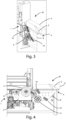
figure 3 shows a perspective view of a detail of a cutting machine that has a cutting unit according to a first embodiment of the present invention; -
figure 4 shows a side view of the cutting machine offigure 3 ; -
figure 5 shows a detail of the detection element of the acquisition unit in a first embodiment; -
figure 6 schematically shows the image acquisition device in a second embodiment of the present invention; -
figure 7 shows a detail of the detection element in the embodiment offigure 6 ; -
figure 8 shows a perspective view of a detail of a cutting machine that has a cutting unit in a third embodiment of the present invention; -
figure 9 shows a side view of the cutting machine offigure 8 ; -
figure 10 shows the acquisition device in the third embodiment of the present invention; -
figure 11 schematically shows a cutting unit associated with a control unit; -
figure 12 shows a perspective view of a second type of machine tool, in particular a machining center. - The description below will refer to the use of a cutting unit in a panel saw, but it must not be considered limited to this specific use, as the cutting unit can also be applied to other types of machines, such as example work centers for carrying out nesting operations.
-
Figure 1 shows a cutting machine of a known type. - In the following description, reference will be made, in a non-limiting way, to a cutting machine M and to wooden panels P or to packs of wooden panels, arranged stacked one on top of the other.
- Referring in particular to
figure 1 , the cutting machine M essentially comprises an input station S1, used for loading/unloading the panel P, at least a processing station S2 to carry out a respective machining on one or more panels P, a station output S3, used for unloading/loading panel P, and a logical control unit, in which pre-established cutting patterns are stored. - Said output station S3 can also be used as a loading station for the panels to be reinserted into the cutting machine M to perform further cuts.
- The panels P that has to be subjected to machining are arranged on a support surface of said loading station S1 and advance on said support surface along a direction of advancement X, until they reach the processing station S2, through the exerted by one or more handling groups, such as pushers, each of which can include one or more gripping and pushing elements, such as for example grippers for gripping and moving the panel P to be processed.
- The processing station S2 comprises a cutting unit and a work surface, on which the panel P to be cut is placed.
- The cutting unit comprises a carriage movable along a processing direction Y, which is in turn orthogonal to said advancement direction X, in a longitudinal chamber formed under said work surface.
- In the cutting machine M, movement means are also provided to move said carriage along said processing direction, in both directions of travel.
- The cutting tool is mounted on said carriage, in particular a circular blade, which slides along said processing direction, performing forward and backward strokes.
- Said circular blade lies on a Y-Z plane, defined by said Y processing direction and by a Z development direction, orthogonal to said X advancement direction and Y machining direction.
- A longitudinal slot is obtained in the same work surface, which extends along said Y processing direction.
- Above said work surface there is a blocking means, such as a pressure member, which extends along said processing direction Y and is movable along said development direction Z, between a raised rest position and a lowered working position, so such as to allow the blocking of the panel P to be worked between the work surface and the pressure member itself.
- Said circular blade is able to cross said longitudinal slot, protruding from said work surface for a given portion, so as to cut the panel P along a cutting line L, parallel to said processing direction Y.
- The blade makes a cut such as to separate at least a first portion P1 of said panel or pack of panels P from the remaining part P2 of the panel or pack of panels P, creating a space S between said first portion P1 and the remaining part P2 of the panel or the pack of panels P, as illustrated in
figure 2 . - Said circular blade is also rotatable around a rotation axis, orthogonal to the aforementioned Y-Z plane and therefore parallel to said direction of advancement X.
-
Figures 4 and5 show a panel saw M, on which acutting unit 1 is installed in a first embodiment of the present invention. - According to the invention, the
cutting unit 1 comprises asupport 2; at least onecutting tool 3 associated with saidsupport 2 and capable of making at least one cut on at least one panel or a pack of panels P, so as to separate at least a first portion P1 of said panel or pack of panels P from the remaining part P2 of the panel or pack of panels P, creating a space S between said first portion P1 and the remaining part P2 of the panel or pack of panels P, saidsupport 2 and said panel or pack of panels P being movable with respect to each other, and adevice 4 for image acquisition capable of being associated with saidsupport 2. - The
image acquisition device 4 comprises at least onedetection element 5, suitable for the insertion into the space S created between said first portion P and the remaining part P2 of the panel or pack of panels P, saiddetection element 5 being suitable for detecting at least azone 6 of the surface of the first portion P1, which overlooks said space S and/or at least a zone 7 of the surface of the remaining part P2 of the panel or pack of panels facing said space. - Preferably the
sensing element 5 is substantially flat. - Advantageously, the
detection element 5 has a thickness such as to fit into the space S created between the first portion P1 and the remaining part P2 of the panel or pack of panels P. - By way of example, the maximum thickness of a single panel is approximately 160 mm. The minimum thickness of the space created between the first portion P1 and the remaining part P2 of the panel or pack of panels P is approximately 4 mm.
- The thickness of the
sensing element 5 is preferably between about 3 mm and about 5 mm, particularly between about 3.6 mm and 4.2 mm. - In the illustrated embodiment the
support 2 is movable with respect to the panel or pack of panels P. - The
cutting tool 3 is a circular blade. - The
circular blade 3 slides along the processing direction, performing back and forth strokes. - Advantageously, the cutting unit includes a
blade 31 for making an incision, in particular a circular blade that rotates in the opposite direction with respect to the cutting blade. - In a first embodiment, illustrated in
figures 3 and 4 , theacquisition device 4 comprises asupport element 8, on which at least onecamera 9 is fixed. Theacquisition device 4 preferably comprises one or two linear cameras. - Advantageously, the
acquisition device 4 comprises at least onelight source 10. - The
light source 10 is advantageously fixed to thesupport element 8. Preferably, the light source comprises a linear LED source. - In an alternative embodiment, the light source can be arranged in the work surface of the machine or in the pressure member.
- The
detection element 5 is arranged in correspondence with the portion of thesupport element 8 opposite to the area in which thecamera 9 is fixed. - In the embodiment illustrated in
figures 3-5 , thesensing element 5 comprises areflective surface 11. Preferably thereflective surface 11 has a sheet metal, for example stainless steel (INOX), with an inclined cut of 45°, in particular mirror-finished (figure 5 ). - The
camera 9 and, if present, thelight source 10, are arranged in the area of the machine M below the panel movement plane P. Thecamera 9 faces the reflectingsurface 11, which fits into the space S created between the subdivided panels. The reflectingsurface 11 is therefore located above the movement plane of the panels P. - In a second embodiment, illustrated schematically in
figure 6 , the acquisition device comprises asupport element 8, on which at least one matrix camera 9' is fixed. Advantageously, theacquisition device 4 comprises at least onelight source 10 fixed to thesupport element 8. Preferably, the light source comprises a linear LED source. - A double reflective surface 11' is arranged in correspondence with the portion of the
support element 8 opposite to the area in which the camera 9' is fixed. Preferably the double reflective surface 11' comprises a metal sheet, for example in stainless steel, with a double inclination cut of 45°, in particular mirror-finished (figure 7 ). - In a third embodiment, illustrated in
figures 8-10 , theacquisition device 41 comprises adetection element 51, in which at least one scanning sensor is integrated. The sensing element is substantially flat. In particular, thesensing element 51 comprises at least one contact image sensor. - Contact Image Sensors (CIS) are image sensors used in flatbed scanners that come into direct contact with the object to be scanned. The CIS sensor is a much smaller sensor than a CCD line sensor, and allows all the necessary optical elements to be included in one compact module.
- Preferably, the
sensing element 51 is substantially rectangular in shape. - In particular, the
sensing element 51 has a length between approximately 50 mm and approximately 300 mm. Thesensing element 51 preferably has a width between about 35 mm and about 45 mm, in particular about 40 mm. - Advantageously, a light source, for example comprising LEDs, is integrated into the
sensing element 51. - As illustrated in
figures 8 and 9 , thesensing element 51 extends above the panel movement plane and fits into the space created between the divided panels. - The
detection element 51 is preferably connected to amodule 52 comprising the acquisition electronics. - In the embodiments illustrated in
figures 3-10 , thesensing element 5 is integral with thesupport 2 to which thecutting tool 3 is associated. - The cutting unit advantageously comprises an encoder 13 arranged on the
support 2. The encoder 13 allows the acquisition of images to be synchronized with the movement speed of the acquisition device, so as to faithfully reconstruct the images of the entire pack of panels. - As illustrated schematically in
figure 11 , the acquisition device is operationally connected to acontrol unit 12. - The
control unit 12 preferably comprises image acquisition software and/or image processing software. - In particular, the
control unit 12 comprises one or more programs for comparing the acquired images with reference images, in order to control the cutting quality. The image processing software preferably comprises Artificial Intelligence software. Pre-trained neural networks can be provided in the software. - Preferably, the
control unit 12 comprises a unit external to the cutting area, for example an edge PC, connected to theacquisition device 4 by cables or wirelessly. - In an alternative embodiment the
control unit 12 is at least partially integrated into the acquisition device. - Advantageously, the
control unit 12 comprises a graphical interface. - In the embodiment illustrated in
figures 8-10 , themodule 52 comprising the acquisition electronics is connected to acontrol unit 12. - According to an aspect of the present invention, the
cutting unit 1 comprising theacquisition device 4 is arranged in a machine tool M for machining panels, in particular wooden panels, such as a panel saw, comprising at least one loading/unloading station S1, S3 of at least one panel or a pack of panels P, a processing station S2 including a work surface, to support said at least one panel or a pack of panels P, a handling unit to move said at least one panel or a pack of panels P along a direction of advancement X, approaching and/or moving away from said processing station S2; and acutting unit 1, wherein thecutting unit 1 is movable along a cutting line L orthogonal to said direction of advancement X, to cut said at least one panel or a pack of panels P. - Advantageously, the
cutting unit 1 is associated with a cleaning device to remove material residues due to processing. This cleaning device can comprise, for example, a blowing nozzle for blowing a pressurized fluid (i.e. air), or a brush, or alternatively an air blade. - According to another aspect of the present invention, the
cutting unit 1 comprising theacquisition device 4 is arranged in a machine tool for machining panels such as a machining center C, comprising asupport plane 15 to support at least one panel P, a machining head 16, opposite to saidsupport surface 15 and equipped with at least one tool for processing said panel P. -
Figure 12 shows a machine tool C known as a work center, in particular for carrying out nesting operations. - The machine C comprises a
support surface 15, generally made of aluminum or Bakelite, for supporting and blocking at least one panel P to be machined. Thesupport surface 15 is arranged on abase 17. - Machine C has a
crosspiece 18, opposite to thesupport plane 15, which can be mobile or fixed with respect to thesupport plane 15, coupled to one or two vertical uprights. Thecrosspiece 18 supports one or more machining heads 16. Generally, each machining head 16 is provided with a spindle, coupled, in use, to a tool holder, which can in turn be coupled to atool 3, for example a cutter. - The machining head 16 is movable along a first 18, and is also mobile along a third Z axis orthogonal to the first of rotation.
- Generally, on the support surface there is a
panel 19, called martyr panel, made of MDF, wood or similar materials. The panel P to be machined is arranged above themartyr panel 19. - In the machine illustrated in
figure 12 , the cutting unit comprises thecrosspiece 18 supporting at least one machining head 16, to which at least one cutting tool is associated. - In the machine illustrated in
figure 12 , in a first embodiment thedetection element 5 of theacquisition device 4 is associated with the machining head during processing and follows the movement of the cutting tool during processing. - In a second embodiment, the
cutting tool 3 carries out the nesting process and subsequently thesensing element 5 is inserted into the space S between the portion of the panel P1 obtained from a first panel P and the remaining part P2 of the first panel and moved along the space S created by the cut. In the second embodiment, thesensing element 5 can be made as an aggregate that can be coupled and decoupled to the spindle of the machining head 16, or it can be arranged on the machining head 16. - The sensing element can be arranged on the
crosspiece 18 on a support, independent of the support of the machining head 16, and movable on thecrosspiece 18 along the Y and Z directions. - Advantageously, the
cutting unit 1 is associated with a cleaning device to remove material residues due to the processing. This cleaning device can comprise, for example, a blowing nozzle for blowing a pressurized fluid (i.e. air), or a brush, or alternatively an air blade. - The present invention also concerns a method of machining panels, in particular wooden panels, comprising the steps of:
- making at least one cut on at least one panel or pack of panels P, to separate at least a first portion P1 of said panel or pack of panels P, from the remaining part P2 of the panel or pack of panels P, creating a space S between said first portion P1 and the remaining part P2 of the panel or pack of panels P;
- inserting a
detection element 5 of an image acquisition device into the space S created between said first portion P1 and the remaining part P2 of the panel or pack of panels P; - capturing at least one image of at least one
area 6 of the surface of the first portion P1 facing said space S and/or at least one area 7 of the surface of the remaining part P2 of the panel or pack of panels P, which faces said space; - comparing the captured image with a reference image.
- Preferably, the method comprises the steps of moving the
detection element 5 along the space S created between said first portion P1 and the remaining part P2 of the panel or pack of panels P;
acquiring at least one image of at least onezone 6 of the surface of the first portion P1 which faces said space S and/or at least one zone 7 of the surface of the remaining part P2 of the panel or pack of panels P which faces said space while moving thesensing element 5.
capturing at least one image of at least one area (6) of the surface of the first portion (P1) facing said space (S) and/or at least one area (7) of the surface of the remaining part (P2) of the panel or pack of panels (P) facing said space during the movement of the detection element (5). - Advantageously, the method comprises a processing step of the acquired image.
- In particular, the processing step and/or the comparison step is carried out using Artificial Intelligence software.
- The present invention has been described for illustrative but not limitative purposes, according to its preferred embodiments, but it is to be understood that modifications and/or changes can be introduced by those skilled in the art without departing from the relevant scope as defined in the enclosed claims.
Claims (17)
- Cutting unit for a panel processing machine, comprising a support (2, 18); at least one cutting tool (3) associated with said support (2, 18) and adapted to make at least one cut on at least one panel or pack of panels (P), so as to separate at least a first portion (P1) of said panel or pack of panels (P) from the remaining part (P2) of the panel or pack of panels (P), creating a space (S) between said first portion (P1) and the remaining part (P2) of the panel or pack of panels (P), said support (2, 18) and said panel or pack of panels (P) being movable with respect to each other; and an image capturing device (4; 41) adapted to be associated with said support (2, 18), said cutting unit being characterized in that said image capturing device (4) comprises at least one detection element (5; 51) adapted to be inserted into the space (S) created between said first portion (P1) and the remaining part (P2) of the panel or pack of panels (P), said detection element (5; 51) being adapted to detect at least one area (6) of the surface of the first portion (P1) facing said space (S) and/or at least one area (7) of the surface of the remaining part (P2) of the panel or pack of panels (P) facing said space (S).
- Cutting unit according to the previous claim, characterized in that said detection element (5) comprises at least one reflecting surface.
- Cutting unit according to any one of the previous claims, characterized in that said capturing device (4) comprises at least one camera (9, 9').
- Cutting unit according to any one of the previous claims 1-3, characterized in that said detection element (51) comprises at least one scanning sensor.
- Cutting unit according to the previous claim, characterized in that said detection element (51) comprises at least one contact image sensor.
- Cutting unit according to any one of the previous claims, characterized in that said detection element (5; 51) is substantially flat.
- Cutting unit according to any one of the previous claims, characterized in that the capturing device (4; 41) comprises at least one light source (10), in particular integrated in the detection element (5; 51).
- Cutting unit according to any one of the previous claims, characterized in that said image capturing device (4; 41) is integral with said support (2).
- Cutting unit according to any one of the previous claims 1-7, characterized in that said image capturing device (4; 41) is movable with respect to said support (2).
- Cutting unit according to any one of the previous claims, characterized in that said detection element (5; 51) is movable along the cutting line made by the cutting tool (3).
- Machine tool for machining panels, in particular wooden panels, comprising at least one loading/unloading station (S1, S3) of at least one panel or pack of panels (P); a processing station (S2) comprising a working plane, to support said at least one panel or pack of panels (P), a movement group to move said at least one panel or pack of panels (P) along a direction of advancement (X), approaching and/or moving away from said processing station (S2); and a cutting unit according to any one of the previous claims, wherein the cutting unit is movable along a cutting line (L) orthogonal to said direction of advancement (X), to cut said at least one panel or pack of panels (P).
- Machine tool for machining panels, in particular wooden panels, comprising a support plane (15) to support at least one panel (P), a machining head (16), opposite to said support surface (15) and equipped with at least one tool (3) for processing said panel (P), said machining head (16) comprising a cutting unit according to any one of the previous claims 1-10.
- Machine tool according to the previous claim, characterized in that said image capturing device (4; 41) is movable with respect to said machining head.
- Machine tool according to any one of claims 11-13, comprising a control unit (12) operatively connected to said image capturing device (4; 41), said control unit (12) being configured to compare the captured images with reference images.
- Method of machining panels, in particular wooden panels, including the steps of:making at least one cut on at least one panel or pack of panels (P), so as to separate at least a first portion (P1) of said panel or pack of panels (P) from the remaining part (P2) of the panel or pack of panels (P), creating a space (S) between said first portion (P1) and the remaining part (P2) of the panel or pack of panels (P);inserting a detection element (5) of an image capturing device into the space (S) created between said first portion (P1) and the remaining part (P2) of the panel or pack of panels (P);capturing at least one image of at least one area (6) of the surface of the first portion (P1) facing said space (S) and/or at least one area (7) of the surface of the remaining part (P2) of the panel or pack of panels (P) facing said space;comparing the captured image with a reference image.
- Method according to the previous claim, comprising the steps of:moving the detection element (5) along the space (S) created between said first portion (P1) and the remaining part (P2) of the panel or pack of panels (P);capturing at least one image of at least one area (6) of the surface of the first portion (P1) facing said space (S) and/or at least one area (7) of the surface of the remaining part (P2) of the panel or pack of panels (P) facing said space during the movement of the detection element (5).
- Method according to any one of claims 15 or 16, comprising a processing step of the captured image.
Applications Claiming Priority (1)
| Application Number | Priority Date | Filing Date | Title |
|---|---|---|---|
| IT102023000027765A IT202300027765A1 (en) | 2023-12-22 | 2023-12-22 | CUTTING UNIT, MACHINE TOOL AND PANEL PROCESSING METHOD. |
Publications (2)
| Publication Number | Publication Date |
|---|---|
| EP4574370A1 true EP4574370A1 (en) | 2025-06-25 |
| EP4574370B1 EP4574370B1 (en) | 2026-04-22 |
Family
ID=90458573
Family Applications (1)
| Application Number | Title | Priority Date | Filing Date |
|---|---|---|---|
| EP24219333.2A Active EP4574370B1 (en) | 2023-12-22 | 2024-12-12 | Cutting unit, machine tool, and method for machining panels |
Country Status (2)
| Country | Link |
|---|---|
| EP (1) | EP4574370B1 (en) |
| IT (1) | IT202300027765A1 (en) |
Citations (4)
| Publication number | Priority date | Publication date | Assignee | Title |
|---|---|---|---|---|
| US6041271A (en) * | 1991-10-10 | 2000-03-21 | Finn-Power International, Inc. | Apparatus to determine the operational effectiveness of a machine tool and method therefor |
| US8210082B2 (en) * | 2006-03-10 | 2012-07-03 | Holzma Plattenaufeil Technik GmbH | Sawing apparatus |
| US20140130643A1 (en) * | 2012-11-13 | 2014-05-15 | Robert Bosch Gmbh | Guard Device For A Table Saw |
| EP2969422B1 (en) * | 2013-03-13 | 2018-08-08 | Robert Bosch GmbH | Power tool having a height adjustment system |
-
2023
- 2023-12-22 IT IT102023000027765A patent/IT202300027765A1/en unknown
-
2024
- 2024-12-12 EP EP24219333.2A patent/EP4574370B1/en active Active
Patent Citations (4)
| Publication number | Priority date | Publication date | Assignee | Title |
|---|---|---|---|---|
| US6041271A (en) * | 1991-10-10 | 2000-03-21 | Finn-Power International, Inc. | Apparatus to determine the operational effectiveness of a machine tool and method therefor |
| US8210082B2 (en) * | 2006-03-10 | 2012-07-03 | Holzma Plattenaufeil Technik GmbH | Sawing apparatus |
| US20140130643A1 (en) * | 2012-11-13 | 2014-05-15 | Robert Bosch Gmbh | Guard Device For A Table Saw |
| EP2969422B1 (en) * | 2013-03-13 | 2018-08-08 | Robert Bosch GmbH | Power tool having a height adjustment system |
Also Published As
| Publication number | Publication date |
|---|---|
| IT202300027765A1 (en) | 2025-06-22 |
| EP4574370B1 (en) | 2026-04-22 |
Similar Documents
| Publication | Publication Date | Title |
|---|---|---|
| JP2003080434A (en) | Device and method for machining workpiece of wood, plastic material or the like | |
| US20190299303A1 (en) | Machining system and machining method | |
| CN115734845A (en) | Workpiece processing device and method for operating a workpiece processing device | |
| EP4574370B1 (en) | Cutting unit, machine tool, and method for machining panels | |
| JPH10175087A (en) | Bar supply device and bar conveyance method in laser processing machine, bar centering / positioning device, bar centering / positioning method, and bar processing method | |
| CN210231943U (en) | Laser deburring equipment | |
| CN216802671U (en) | Blade machining system with upper cutter mechanism | |
| KR101356061B1 (en) | Apparatus for automatically manufacturing working piece for impact test piece | |
| CN110977480A (en) | Combined sawing machine for cutting and milling | |
| CN120326696B (en) | Slicing mechanism and fruit processing equipment | |
| CN223147251U (en) | Fruit slicing device and fruit processing equipment | |
| JP2801910B1 (en) | Long material transfer device | |
| KR20240073378A (en) | metal plate cutting automation system | |
| JP4683750B2 (en) | Cutting apparatus and cutting method using the apparatus | |
| JP3302644B2 (en) | Kiguchi processing machine and pre-cut processing equipment | |
| CN109789474B (en) | Machine tool and method for machining plate-shaped workpieces | |
| CN219996104U (en) | Measuring mechanism of bamboo sawing machine | |
| KR102826704B1 (en) | Jig for fixing cuttings of a cutter | |
| CN223161018U (en) | Fruit slicing device and fruit processing equipment | |
| CN115519180B (en) | Circular sawing machine | |
| US20040123711A1 (en) | Fully automatic cutting metal-working machine | |
| EP1258306A2 (en) | System for detecting size unevennesses of cut-stock boards | |
| CN219302287U (en) | Detection device and processing machine | |
| KR20240056859A (en) | Cutting apparatus for keyway of gear | |
| JP2020131319A (en) | Grinding device and grinding method |
Legal Events
| Date | Code | Title | Description |
|---|---|---|---|
| PUAI | Public reference made under article 153(3) epc to a published international application that has entered the european phase |
Free format text: ORIGINAL CODE: 0009012 |
|
| STAA | Information on the status of an ep patent application or granted ep patent |
Free format text: STATUS: THE APPLICATION HAS BEEN PUBLISHED |
|
| AK | Designated contracting states |
Kind code of ref document: A1 Designated state(s): AL AT BE BG CH CY CZ DE DK EE ES FI FR GB GR HR HU IE IS IT LI LT LU LV MC ME MK MT NL NO PL PT RO RS SE SI SK SM TR |
|
| STAA | Information on the status of an ep patent application or granted ep patent |
Free format text: STATUS: REQUEST FOR EXAMINATION WAS MADE |
|
| 17P | Request for examination filed |
Effective date: 20251201 |
|
| GRAP | Despatch of communication of intention to grant a patent |
Free format text: ORIGINAL CODE: EPIDOSNIGR1 |
|
| STAA | Information on the status of an ep patent application or granted ep patent |
Free format text: STATUS: GRANT OF PATENT IS INTENDED |
|
| RIC1 | Information provided on ipc code assigned before grant |
Ipc: B27M 1/08 20060101AFI20251230BHEP Ipc: B27B 5/065 20060101ALI20251230BHEP Ipc: B27G 19/08 20060101ALI20251230BHEP Ipc: B23D 59/00 20060101ALI20251230BHEP |
|
| INTG | Intention to grant announced |
Effective date: 20260115 |
|
| GRAS | Grant fee paid |
Free format text: ORIGINAL CODE: EPIDOSNIGR3 |
|
| GRAA | (expected) grant |
Free format text: ORIGINAL CODE: 0009210 |
|
| STAA | Information on the status of an ep patent application or granted ep patent |
Free format text: STATUS: THE PATENT HAS BEEN GRANTED |
|
| AK | Designated contracting states |
Kind code of ref document: B1 Designated state(s): AL AT BE BG CH CY CZ DE DK EE ES FI FR GB GR HR HU IE IS IT LI LT LU LV MC ME MK MT NL NO PL PT RO RS SE SI SK SM TR |
|
| REG | Reference to a national code |
Ref country code: CH Ref legal event code: F10 Free format text: ST27 STATUS EVENT CODE: U-0-0-F10-F00 (AS PROVIDED BY THE NATIONAL OFFICE) Effective date: 20260422 Ref country code: GB Ref legal event code: FG4D |
|
| REG | Reference to a national code |
Ref country code: DE Ref legal event code: R096 Ref document number: 602024004201 Country of ref document: DE |