EP4574195A2 - Osteotome with inflatable portion and multiwire articulation - Google Patents
Osteotome with inflatable portion and multiwire articulation Download PDFInfo
- Publication number
- EP4574195A2 EP4574195A2 EP25161660.3A EP25161660A EP4574195A2 EP 4574195 A2 EP4574195 A2 EP 4574195A2 EP 25161660 A EP25161660 A EP 25161660A EP 4574195 A2 EP4574195 A2 EP 4574195A2
- Authority
- EP
- European Patent Office
- Prior art keywords
- bone displacement
- stylet
- bone
- outer tube
- displacement device
- Prior art date
- Legal status (The legal status is an assumption and is not a legal conclusion. Google has not performed a legal analysis and makes no representation as to the accuracy of the status listed.)
- Pending
Links
Images







Classifications
-
- A—HUMAN NECESSITIES
- A61—MEDICAL OR VETERINARY SCIENCE; HYGIENE
- A61B—DIAGNOSIS; SURGERY; IDENTIFICATION
- A61B17/00—Surgical instruments, devices or methods
- A61B17/56—Surgical instruments or methods for treatment of bones or joints; Devices specially adapted therefor
- A61B17/58—Surgical instruments or methods for treatment of bones or joints; Devices specially adapted therefor for osteosynthesis, e.g. bone plates, screws or setting implements
- A61B17/88—Osteosynthesis instruments; Methods or means for implanting or extracting internal or external fixation devices
- A61B17/885—Tools for expanding or compacting bones or discs or cavities therein
- A61B17/8852—Tools for expanding or compacting bones or discs or cavities therein capable of being assembled or enlarged, or changing shape, inside the bone or disc
- A61B17/8855—Tools for expanding or compacting bones or discs or cavities therein capable of being assembled or enlarged, or changing shape, inside the bone or disc inflatable, e.g. kyphoplasty balloons
-
- A—HUMAN NECESSITIES
- A61—MEDICAL OR VETERINARY SCIENCE; HYGIENE
- A61B—DIAGNOSIS; SURGERY; IDENTIFICATION
- A61B17/00—Surgical instruments, devices or methods
- A61B17/16—Instruments for performing osteoclasis; Drills or chisels for bones; Trepans
- A61B17/1662—Instruments for performing osteoclasis; Drills or chisels for bones; Trepans for particular parts of the body
- A61B17/1671—Instruments for performing osteoclasis; Drills or chisels for bones; Trepans for particular parts of the body for the spine
-
- A—HUMAN NECESSITIES
- A61—MEDICAL OR VETERINARY SCIENCE; HYGIENE
- A61M—DEVICES FOR INTRODUCING MEDIA INTO, OR ONTO, THE BODY; DEVICES FOR TRANSDUCING BODY MEDIA OR FOR TAKING MEDIA FROM THE BODY; DEVICES FOR PRODUCING OR ENDING SLEEP OR STUPOR
- A61M25/00—Catheters; Hollow probes
- A61M25/01—Introducing, guiding, advancing, emplacing or holding catheters
- A61M25/0105—Steering means as part of the catheter or advancing means; Markers for positioning
- A61M25/0133—Tip steering devices
- A61M25/0147—Tip steering devices with movable mechanical means, e.g. pull wires
-
- A—HUMAN NECESSITIES
- A61—MEDICAL OR VETERINARY SCIENCE; HYGIENE
- A61B—DIAGNOSIS; SURGERY; IDENTIFICATION
- A61B17/00—Surgical instruments, devices or methods
- A61B2017/00535—Surgical instruments, devices or methods pneumatically or hydraulically operated
- A61B2017/00557—Surgical instruments, devices or methods pneumatically or hydraulically operated inflatable
-
- A—HUMAN NECESSITIES
- A61—MEDICAL OR VETERINARY SCIENCE; HYGIENE
- A61M—DEVICES FOR INTRODUCING MEDIA INTO, OR ONTO, THE BODY; DEVICES FOR TRANSDUCING BODY MEDIA OR FOR TAKING MEDIA FROM THE BODY; DEVICES FOR PRODUCING OR ENDING SLEEP OR STUPOR
- A61M25/00—Catheters; Hollow probes
- A61M25/01—Introducing, guiding, advancing, emplacing or holding catheters
- A61M25/0105—Steering means as part of the catheter or advancing means; Markers for positioning
- A61M25/0133—Tip steering devices
- A61M25/0136—Handles therefor
Definitions
- the present disclosure relates generally to medical devices used to treat tissue, including bone. More specifically, in certain embodiments, the present disclosure relates to medical devices used to displace tissue using an expandable member, such as a balloon.
- Tissue treatment devices may include elongate members, expandable members, and other components.
- an elongate member of a tissue treatment device may be advanced to a treatment location and an expandable member expanded to displace tissue.
- a bone displacement device may be disposed within a vertebra of a patient and an expandable member expanded to displace portions of the vertebra.
- such devices may be utilized in other areas of the body with other types of tissue.
- this disclosure references "bone displacement" or “bone displacement devices,” however, such disclosure may be analogously applied to devices, elements, and procedures configured to displace or otherwise treat tissue in other portions of the body.
- a bone displacement device may include an elongate outer tube.
- a stylet may be coaxially disposed within the outer tube.
- a proximal portion of the outer tube and the stylet shaft may be attached to a handle.
- the stylet comprises a plurality of pull wires coaxially disposed within a shaft of the stylet.
- a distal portion of the stylet may be articulated when a tension force is applied to the plurality of pull wires.
- a portion of the handle is configured as an actuator to articulate the stylet.
- the handle comprises a rotatable grip having female threads configured to engage with male threads of a pull member. The threads may include thread stops to limit rotation of the rotatable grip.
- a distal portion of the plurality of pull wires is coupled to the pull member.
- rotation of the rotatable grip in the first direction proximally displaces the pull member and thus applies a tension force to the pull wires to articulate the distal portion of the stylet.
- the handle may also include a side port having a valve.
- Certain bone displacement devices include an expandable member, such as a balloon.
- the expandable member may be disposed at a distal portion of the bone displacement device.
- a proximal portion of the expandable member is attached to a distal portion of the outer tube via a tie layer.
- a distal portion of the expandable member can be attached to a tip tie tube.
- the tip tie tube may be longitudinally displaceable over the distal portion of the stylet.
- a protective sleeve may be disposed around the balloon when the bone displacement device is in its package, and displaced proximally over the outer tube to engage with the handle when the bone displacement device is ready to use.
- a bone displacement device may be used by a practitioner to treat a fractured bone, such as a vertebral bone.
- the practitioner may displace bone by inflating an expandable member at a distal end of the bone displacement device to create a cavity into which a bone stabilizing material, such as bone cement, may be injected.
- the rotatable grip may be rotated in a first direction to apply a tension force to pull wires to articulate a distal portion of the bone displacement device.
- the distal portion of the bone displacement device may be directed - via articulation of the distal portion and/or displacement of the entire bone displacement device - to a desired location within the bone.
- the expandable member can be expanded to displace bone tissue adjacent the expandable member to create a cavity.
- the bone displacement device can be removed from the bone to allow for injection of bone cement into the cavity.
- Coupled to and in communication with refer to any form of interaction between two or more entities, including mechanical, electrical, magnetic, electromagnetic, fluid, and thermal interaction.
- Two components may be coupled to or in communication with each other even though they are not in direct contact with each other.
- two components may be coupled to or in communication with each other through an intermediate component.
- distal and proximal are given their ordinary meaning in the art. That is, the distal end of a medical device means the end of the device furthest from the practitioner during use.
- the proximal end refers to the opposite end, or the end nearest the practitioner during use.
- the proximal end of the device refers to the end nearest the handle and the distal end refers to the opposite end, the end nearest a working tip of the device.
- proximal end always refers to the handle end of the device (even if the distal end is temporarily closer to the physician).
- Fluid is used in its broadest sense, to refer to any fluid, including both liquids and gases as well as solutions, compounds, suspensions, etc., which generally behave as fluids.
- FIGS. 1A-14B illustrate different views of several bone displacement devices or osteotomes and related components.
- each device may be coupled to, or shown with, additional components not included in every view.
- additional components not included in every view.
- additional components are illustrated, to provide detail into the relationship of the components.
- Some components may be shown in multiple views, but not discussed in connection with every view. Disclosure provided in connection with any figure is relevant and applicable to disclosure provided in connection with any other figure or embodiment.
- FIGS. 1A-4B depict an embodiment of a bone displacement device 100.
- the bone displacement device 100 comprises a handle 110, a catheter 130, a stylet 140, and an expandable member 150.
- FIG. 1A shows the bone displacement device 100 in a ready state where the expandable member 150 is not expanded and a distal portion of the bone displacement device 100 is not articulated.
- FIG. 1B shows the bone displacement device 100 in a bone displacement or cavity forming state where the expandable member 150 is expanded and the distal portion is articulated.
- FIG. 2 illustrates a proximal portion of the bone displacement device 100.
- the proximal portion may comprise the handle 110, a proximal portion of the catheter 130, and a proximal portion of the stylet 140.
- the catheter 130 may comprise an elongate outer tube 131 and an elongate inner tube 135.
- the outer tube 131 may comprise a proximal portion 132.
- the outer tube 131 can be formed from any suitable polymeric material.
- the outer tube 131 may be formed from polyurethane, nylon, PBT, polyethylene, polypropylene, etc.
- a proximal end of outer tube 131 can be fixedly coupled to the handle 110.
- the inner tube 135 is coaxially disposed within the outer tube 131.
- the inner tube 135 may be formed from any of the materials listed in connection with the outer tube 131, though the inner tube 135 and outer tube 131 may or may not be formed of the same material.
- a proximal end of the inner tube 135 can be fixedly coupled to the handle 110 at a location proximal of the proximal end of the outer tube 131.
- the stylet 140 is shown to comprise a tubular shaft 141.
- the shaft 141 may be formed from any suitable rigid material, such as stainless steel, titanium, nitinol, etc.
- a proximal end of the shaft 141 may be fixedly coupled to the handle 110 at a location proximal of the proximal end of the inner tube 135.
- One or more pull wires 142 can be coaxially disposed within the shaft 141.
- the pull wires 142 include a plurality of pull wires comprising seven pull wires. In other embodiments, the number of pull wires 142 may be three, four, five, six, eight, or more pull wires.
- the pull wires 142 may extend proximally from the shaft 141 and be fixedly coupled to the distal end of the shaft 141.
- the pull wires 142 may be formed from any suitable material with high tensile strength.
- the pull wires 142 may be formed from stainless steel, titanium, nitinol, etc.
- a diameter of the pull wires 142 may range from about 0.005 inch to about 0.030 inch.
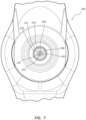
- FIG. 3 illustrates a transverse cross-section of a middle portion of the bone displacement device 100.
- the outer tube 131 includes an outer lumen 134.
- the inner tube 135 is shown to be coaxially disposed within the outer lumen 134.
- An annular space 139 may be formed between the outer tube 131 and the inner tube 135.
- the inner tube 135 may include an inner lumen 138.
- the shaft 141 may be coaxially disposed within the inner lumen 138.
- the shaft 141 is shown to include a shaft lumen 143.
- the pull wires 142 are disposed within the shaft lumen 143. As depicted in FIG. 3 , the pull wires 142 collectively include seven individual pull wires 148.
- the individual pull wires 148 are disposed with a first individual pull wire 148 centrally located and the remaining six individual pull wires 148 equally spaced around the first individual pull wire 148.
- the pull wires 148 are shown as individual strands disposed longitudinally adjacent each other (without braiding or twisting) in the illustrated embodiment. This configuration of the pull wires 148 may be configured to provide adequate stiffness to the bone displacement device 100 to the ready state where the distal portion of the bone displacement device 100 is not articulated and/or to facilitate transfer of force to straighten the bone displacement device 100 from an articulated configuration to a non articulated configuration.
- each pull wire 148 may be formed in a braid of a plurality of smaller diameter wires. Other arrangements of the pull wires 148 are likewise within the scope of this disclosure, including embodiments where the individual wires are braided or twisted into a cable.
- the handle 110 may comprise a body 111 and a rotatable grip 112 rotatably coupled to a proximal end of the body 111.
- the body 111 and rotatable grip 112 may be formed from any suitable polymeric material, such as polycarbonate, acrylonitrile butadiene styrene, etc.
- the body 111 may comprise a side port 124.
- the side port 124 extends generally proximally and laterally from a longitudinal axis of the body 111.
- the side port 124 may extend at an angle ranging from 15 degrees to 90 degrees or about 45 degrees relative to the longitudinal axis.
- the side port 124 may be in fluid communication with the annular space (139 of FIG.
- a fluid delivery device e.g., syringe
- a fluid delivery device can be releasably coupled to a proximal portion of the side port 124.
- a valve member 122 may be disposed within the side port 124.
- the valve member 122 may be configured to selectively permit air or fluid to be directed from the fluid delivery device, through the side port 124, through the annular space 139, and then to the expandable member (150 of FIG. 1A ) when the fluid delivery device is coupled to the side port 124.
- the valve member 122 may also be configured to retain the air or fluid within the annular space 139 and the expandable member 150 when the fluid delivery device is removed from the side port 124.
- the proximal end of the outer tube 131 is coupled to the body 111 at a location distal to the side port 124, and the inner tube 135 is coupled to the body 111 at a location proximal to the side port 124.
- a proximal end of the shaft 141 can be coupled to the body 111 at a location proximal to the inner tube 135.
- the rotatable grip 112 may be configured to be rotated around a longitudinal axis of the handle 110. As depicted, the rotatable grip 112 may comprise laterally extending wings 113 configured to be gripped by a user. In other embodiments, the rotatable grip 112 may comprise any suitable feature to facilitate gripping and rotation of the rotatable grip 112. For example, the rotatable grip 112 may comprise a knob including grippable features, such as ridges, bumps, recesses, textured surface, etc. The rotatable grip 112 may comprise a chamber 119 configured to receive a pull member 116.
- the pull member 116 of the illustrated embodiment is configured as non-rotatable relative to the rotatable grip 112, or configured not to rotate with the rotatable grip 112.
- the chamber 119 may include a female thread 114 configured to engage a male thread 117 of the pull member 116.
- the female thread 114 may comprise proximal and distal female thread stops 115.
- the female thread stops 115 may include a flat face oriented perpendicular to a longitudinal axis of the rotatable grip 112.
- the female thread stops 115 may include a tapered face.
- the pull member 116 may include a male thread 117 configured to engage with the female thread 114.
- the male thread 117 may comprise proximal and distal male thread stops 118.
- the male thread stops 118 may include a flat face oriented perpendicular to a longitudinal axis of the pull member 116.
- the male thread stops 118 may include a tapered face.
- the female thread stops 115 can be configured to engage with the male thread stops 118 to prevent over-rotation of the rotatable grip 112 in both a first direction and a second direction. In some instances, over-rotation of the rotatable grip 112 may result in excess strain or breakage of the shaft 141 and/or one or more of the individual pull wires 148.
- the threads may be configured with a positive stop to minimize excess force and subsequent breakage.
- the chamber 119 may include a male thread 117 and male thread stops 118 while the pull member 116 includes a female thread 114 and female thread stops 115.
- the proximal ends of the pull wires 142 may be fixedly coupled to the pull member 116.
- the pull member 116 When the rotatable grip 112 is rotated in the first direction, the pull member 116 is displaced proximally, causing a tension force to be equally or substantially equally applied to all of the individual pull wires 148.
- Embodiments wherein one or more individual pull wires 148 transmit an uneven or larger portion of the tension force are likewise within the scope of this disclosure.
- the tension force on the pull wires 142 may result in a tension force being applied to the distal end of the stylet 140 and articulation of the distal portion of the bone displacement device 100, as shown in FIG. 1B .
- the rotatable grip 112 may be rotated from about one degree to about 540 degrees, from about one degree to about 360 degrees, or from about one degree to about 180 degrees, or along any portion of these ranges.
- Rotation of the rotatable grip 112 in the first direction may be stopped when the proximal female thread stop 115 engages with the proximal male thread stop 118, or may be stopped at any point along the range of rotation of the rotatable grip 112, meaning it is stopped by a user at a point of partial rotation along the rotational range of the rotatable grip 112.
- Rotation of the rotatable grip 112 and proximal displacement of the pull member 116 may result in an articulation of the distal portion of the bone displacement device 100 from about zero degrees to about 180 degrees, from about zero degrees to about 135 degrees, or from about zero degrees to about 90 degrees.
- the rotatable grip 112 may comprise a rotation lock configured to maintain the rotatable grip 112 in a partial or fully rotated state when the rotatable grip 112 is released by the user.
- the body 111 may comprise teeth configured to engage with opposing teeth of the rotatable grip 112.
- Rotation of the rotatable grip 112 in the second direction may displace the pull member 116 distally and release the tension force on the pull wires 142, resulting in the distal portion of the bone displacement device 100 returning to a straight configuration, as shown in FIG. 1A .
- the rotatable grip 112 can be rotated in the second direction until the distal female thread stop 115 engages with the distal male thread stop 118.
- FIGS. 4A-4B illustrate a distal portion of the bone displacement device 100.
- the distal portion may comprise the expandable member 150, a distal portion 133 of the outer tube 131, a distal portion 137 of the inner tube 135, and a distal portion 145 of the shaft 141.
- the inner tube 135 and the shaft 141 may extend beyond a distal end of the outer tube 131.
- the inner tube 135 may extend beyond a distal end of the shaft 141.
- the expandable member 150 comprises a balloon 151.
- the expandable member 150 may comprise any suitable expandable and retractable mechanism.
- the expandable member 150 may comprise a plurality of ribs configured to expand radially outward.
- the balloon 151 may comprise a double balloon wall 152 configured to expand radially outward without stretching when air or fluid is injected into the balloon 151, for example, through the annular space 139.
- a thickness of the double balloon wall 152 may range from about 0.020 mm to about 0.038 mm or from about .025 mm to about 0.030 mm.
- a length of the balloon 151 when not inflated or expanded may range from about 10 mm to about 30 mm.
- the balloon 151 may be formed of any suitable non-compliant polymeric material, such as engineered plastic polyurethane (e.g., Isoplast ® ), nylon, polybutylene terephthalate, etc.
- a proximal portion of the balloon 151 may be sealingly coupled to the distal end of the outer tube 131.
- a tie layer 153 may be disposed between the balloon wall 152 and the outer tube 131 to facilitate bonding of the balloon wall 152 to the outer tube 131. In other embodiments, the tie layer 153 is not used to facilitate bonding of the balloon wall 152 to the outer tube 131.
- the tie layer 153 may be formed from a polyurethane material having an intermediate hardness that is between the hardness of the material of the balloon 151 and the hardness of the material of the outer tube 131.
- the balloon wall 152 may be bonded to the tie layer 153 and the outer tube 131 using any suitable technique, such as heat, radio frequency, solvent bonding, gluing, etc.
- a distal portion of the balloon 151 may be sealingly coupled to the distal end of the inner tube 135.
- a tip tie tube 155 may be disposed between the balloon wall 152 and the inner tube 135.
- the tip tie tube 155 may be formed from a material similar to the tie layer 153.
- the tip tie tube 155 may comprise a braided structure.
- the tip tie tube 155 may extend proximally over the distal portion 137 of the inner tube 135 and the distal portion 145 of the shaft 141.
- the tip tie tube 155 and shaft 141 may configured in a "piston/cylinder" type arrangements where the shaft 141 is allowed to move with respect to the tip tie tube when the balloon 151 is inflated or deflated.
- the tip tie tube 155 may be configured to piston proximally over the shaft 141 when the balloon 151 is inflated and to piston distally over the shaft 141 when the balloon 151 is deflated.
- the tip tie tube 155 may be configured to facilitate bonding of the balloon wall 152 to the inner tube 135.
- the tip tie tube 155 may provide structural support to the inner tube 135 to prevent kinking of the inner tube 135 when inserted into a vertebral bone.
- the seal of the proximal end of the balloon 151 to the outer tube 131 and the seal of the distal end of the balloon 151 to the inner tube 135 may form a balloon chamber 156 configured to be pressurized.
- the balloon chamber 156 may be pressurized up to a pressure of about 60 atm.
- the balloon 151 may be expanded to a diameter of from about 10 mm to about 30 mm.
- the distal portion 145 of the shaft 141 may comprise a plurality of laser cuts 147.
- the laser cuts 147 may facilitate articulation of the shaft 141 in a single plane when the tension force is applied to the pull wires 142, as shown in FIG 1B .
- the laser cuts 147 may comprise variables (e.g., depth, pitch, spacing) that control the articulation parameters of the shaft 141, such as angle of articulation.
- the laser cuts 147 may comprise a tab configured to be received by a recess. The laser cuts 147 of this embodiment may prevent torsional rotation of the laser cuts 147 relative to one another.
- the pull wires 142 may also prevent torsional rotation of the laser cuts 147 because the pull wires 142 substantially fill the shaft lumen 143 preventing axial misalignment of the laser cuts 147.
- the laser cuts 147 may extend partially through a diameter of the shaft 141, leaving a spine of uncut material. When articulated, the shaft 141 may bend toward the spine while a distance between shaft segments on either side of the laser cuts 147 increases on an opposing side of the shaft 141, defining a substantially "V" shape.
- the shaft 141 may break at one of the laser cuts 147 when the shaft 141 is articulated. This may be due to external forces (such as from the bone) acting on the shaft 141.
- the pull wires 142 may prevent a portion of the shaft 141 distal to the break from breaking away from a remainder of the shaft 141. Even if one of the individual pull wires 148 also breaks, the remaining individual pull wires 148 may retain attachment to the distal end of the shaft 141.
- the pull wires 142 may maintain the coaxial arrangement of the shaft 141, inner tube 135, and outer tube 131 and prevent leakage of air or fluid from the bone displacement device 100 caused by damage to the inner tube 135 and/or outer tube 131 by a broken end of the shaft 141 of a pull wire 148 .
- a bone displacement device may be used to displace bone tissue.
- a distal end of the bone displacement device may be inserted into a vertebral bone, for example, through an introducer cannula.
- a distal portion of the bone displacement device may be articulated when a rotatable grip is rotated in a first direction, causing one or more pull members to be displaced proximally.
- Proximal displacement of the pull member may apply a tension force to pull wires disposed within a stylet shaft and coupled to the pull member.
- the tension force applied to the pull wires can cause a distal portion of a stylet to articulate the distal portion of the bone displacement device.
- the articulated bone displacement device can be directed to a desired location within the vertebral bone.
- a syringe may be coupled to a side port of a handle. Air or fluid may be delivered through the side port to an expandable member (e.g., balloon) disposed adjacent the distal end of the bone displacement device. The air or fluid may expand the expandable member to displace adjacent bone tissue.
- an expandable member e.g., balloon
- FIGS. 5A-8B depict an embodiment of a bone displacement device 200 that resembles the bone displacement device 100 described above in certain respects. Accordingly, like features are designated with like reference numerals, with the leading digit incremented to "2."
- the embodiment depicted in FIGS. 5A-8B includes a handle 210 that may, in some respects, resemble the handle 110 of FIG. 1A . Relevant disclosure set forth above regarding similarly identified features thus may not be repeated hereafter.
- specific features of the bone displacement device 100 and related components shown in FIGS. 1A-4A may not be shown or identified by a reference numeral in the drawings or specifically discussed in the written description that follows.
- FIGS. 5A-8B depict another embodiment of a bone displacement device 200.
- the bone displacement device 200 comprises a handle 210, a catheter 230, a stylet 240, and an expandable member 250.
- FIG. 5A shows the bone displacement device 200 in a ready state where the expandable member 250 is not expanded and a distal portion of the bone displacement device 200 is substantially straight.
- FIG. 5B shows the bone displacement device 200 in a cavity forming state where the expandable member 250 is expanded and the distal portion is articulated.
- FIG. 6 illustrates a proximal portion of the bone displacement device 200.
- the proximal portion may comprise the handle 210, a proximal portion of the catheter 230, and a proximal portion of the stylet 240.
- the catheter 230 may comprise an elongate outer tube 231 having a proximal portion 232. A proximal end of the outer tube 231 can be fixedly coupled to the handle 210.
- the stylet 240 is shown to comprise a tubular shaft 241 having a proximal portion 244. A proximal end of the shaft 241 may be fixedly coupled to the handle 210 at a location proximal of the proximal end of the outer tube 231. One or more pull wires 242 can be disposed within the shaft 241.
- FIG. 7 illustrates a transverse cross-section of a middle portion of the bone displacement device 200.
- the outer tube 231 includes an outer lumen 234.
- the shaft 241 may be coaxially disposed within the outer lumen 234.
- An annular space 239 may be formed between the outer tube 231 and the shaft 241.
- the shaft 241 may include a shaft lumen 243.
- the pull wires 242 can be disposed within the shaft lumen 243.
- the handle 210 may comprise a body 211 and a rotatable grip 212 rotatably coupled to a proximal end of the body 211.
- the body 211 may comprise a side port 224 extending laterally from a longitudinal axis of the body 211.
- the side port 224 may be in fluid communication with the annular space (239 of FIG. 7 ).
- a fluid delivery device e.g., syringe
- a valve member 222 may be disposed within the side port 124.
- the valve member 222 may be configured to selectively permit air or fluid to be directed through the side port 224, through the annular space 239, and to the expandable member 250 when the fluid delivery device is coupled to the side port 224.
- the valve member 222 may also be configured to retain the air or fluid within the annular space 239 and the expandable member 250 when the fluid delivery device is removed from the side port 224.
- the proximal end of the outer tube 231 can be coupled to the body 211 at a location distal to the side port 224.
- the shaft 241 can be coupled to the body 211 at a location proximal to the outer tube 231.
- the rotatable grip 212 may be configured to be rotatable around a longitudinal axis of the handle 210.
- the rotatable grip 212 may comprise generally laterally and proximally extending wings 213 configured to be gripped by a user.
- the rotatable grip 212 may comprise a chamber 219 configured to receive a pull member 216.
- the chamber 219 may include a female thread 214 configured to engage a male thread 217 of the pull member 216.
- the female thread 214 may comprise proximal and distal thread stops 215.
- the male thread 217 may comprise proximal and distal thread stops 218.
- the female thread stops 215 can be configured to engage with the male thread stops 218 to prevent over-rotation of the rotatable grip 212 in both a first direction and a second direction.
- the proximal ends of the pull wires 242 may be fixedly coupled to the pull member 216.
- the pull member 216 can be displaced proximally, causing a tension force to be applied to the pull wires 242.
- the tension force on the pull wires 242 may result in a tension force being applied to the distal end of the shaft 241 and articulation of the shaft 241 and the bone displacement device 200, as shown in FIG. 5B .
- Rotation of the rotatable grip 212 in the second direction may displace the pull member 216 distally and release the tension force on the pull wires 242, resulting in the distal portion of the bone displacement device 200 returning to a substantially straight configuration, as shown in FIG. 5A .
- the rotatable grip 212 can be rotated in the second direction until the distal female thread stop 215 engages with the distal male thread stop 218.
- FIGS. 8A-8B illustrate a distal portion of the bone displacement device 200.
- the distal portion may comprise an expandable member 250, a distal portion 233 of the outer tube 231, and a distal portion 245 of the shaft 241.
- the shaft 241 may extend beyond the distal end of the outer tube 231.
- the expandable member 250 comprises a balloon 251.
- the balloon 251 may comprise a balloon wall, such as a double balloon wall 252 configured to expand radially outward without stretching when air or fluid is injected into the balloon 251 through the annular space 239.
- a proximal portion of the balloon 251 may be sealingly coupled to the distal end of the outer tube 231.
- a tie layer 253 may be disposed between the balloon wall 252 and the outer tube 231 to facilitate bonding of the balloon wall 252 to the outer tube 231.
- a distal portion of the balloon 251 may be sealingly coupled to a distal end of a tip tie tube 255.
- the tip tie tube 255 may extend proximally over the distal portion 245 of the shaft 241.
- the tip tie tube 255 and shaft 241 may configured in a "piston/cylinder" type arrangements where the shaft 214 is allowed to move with respect to the tip tie tube when the balloon 251 is inflated or deflated.
- the tip tie tube 255 may be configured to piston proximally over the shaft 241 when the balloon 251 is inflated and to piston distally over the shaft 241 when the balloon 251 is deflated.
- a plug 254 may be sealingly disposed within the distal end of the tip tie tube 255.
- the seal of the proximal end of the balloon 251 to the outer tube 231 and the seal of the distal end of the balloon 251 to the tip tie tube 255 may form a balloon chamber 256 configured to be pressurized.
- the balloon chamber 256 may be pressurized up to a pressure of about 60 atm.
- the balloon 251 may be expanded to a diameter of from about 10 mm to about 30 mm.
- the distal portion of the shaft 241 may comprise a plurality of laser cuts 247.
- the laser cuts 247 may facilitate articulation of the shaft 241 when the tension force is applied to the pull wires 242, as shown in FIG 8B .
- FIGS. 9A-13B depict another embodiment of a bone displacement device 300.
- the bone displacement device 300 is partially composed of a handle 310, a catheter 330, a stylet 340, and an expandable member 350.
- FIG. 9A shows the bone displacement device 300 in a ready state where the expandable member 350 is not expanded and a distal portion of the bone displacement device 300 is substantially straight.
- FIG. 9B shows the bone displacement device 300 in a cavity forming state where the expandable member 350 is expanded and the distal portion is substantially straight.
- FIG. 10 illustrates a proximal portion of the bone displacement device 300.
- the proximal portion may comprise the handle 310, a proximal portion of the catheter 330, and a proximal portion of the stylet 340.
- the catheter 330 may comprise an elongate outer tube 331 and an elongate inner tube 335.
- a proximal end of outer tube 331 can be coupled to the handle 310.
- the inner tube 335 may be coaxially disposed within the outer tube 331.
- a proximal end of the inner tube 335 can be coupled to the handle 310 at a location proximal of the proximal end of the outer tube 331.
- the handle 310 may comprise a body 311.
- the body 311 may comprise a side port 324 extending laterally from a longitudinal axis of the body 311.
- the side port 324 may be in fluid communication with an annular space (339 of FIG. 12 ).
- a fluid delivery device e.g., syringe
- a valve member 322 may be disposed within the side port 324. The valve member 322 may be configured to selectively permit air or fluid to be directed through the side port 324, through the annular space 339, and to the expandable member 350 when the fluid delivery device is coupled to the side port 324.
- the valve member 322 may also be configured to retain the air or fluid within the annular space 339 and the expandable member 350 when the fluid delivery device is removed from the side port 324.
- the body 311 may include a proximal port 325 in fluid communication with the inner tube 335.
- the proximal port 325 may be configured to receive the stylet 340.
- the proximal port 325 may include a female luer taper and a thread engagement feature.
- the proximal end of the outer tube 331 can be coupled to the body 311 at a location distal to the side port 324.
- the inner tube 335 can be coupled to the body 311 at a location proximal to the outer tube 331.
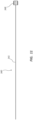
- FIG. 11 depicts the stylet 340.
- the stylet 340 may comprise a shaft 341 and a connector 348.
- the shaft 341 may be a cylindrical rod. In other embodiments, the shaft 341 may be a cylindrical tube. A proximal end of the shaft 341 may be fixedly coupled to the connector 348.
- the connector 348 is a male luer nut.
- the connector 348 may be configured to be removably coupled to the proximal port 325 such that the stylet 340 may be inserted into and removed from the bone displacement device 300 through the proximal port 325.
- FIG. 12 illustrates a transverse cross-section of a middle portion of the bone displacement device 300.
- the outer tube 331 includes an outer lumen 334.
- the inner tube 335 is shown to be coaxially disposed within the outer lumen 334.
- An annular space 339 may be defined between the outer tube 331 and the inner tube 335.
- the inner tube may include an inner lumen 338.
- the shaft 341 may be coaxially disposed within the inner lumen 338.
- FIGS. 13A-13B illustrate a distal portion of the bone displacement device 300.
- the distal portion may comprise an expandable member 350, a distal portion 333 of the outer tube 331, a distal portion 337 of the inner tube 335, and a distal portion 345 of the shaft 341.
- the inner tube 335 and the shaft 341 may extend beyond the distal end of the outer tube 331.
- the inner tube 335 may extend beyond the distal end of the shaft 341.
- the expandable member 350 comprises a balloon 351.
- a proximal portion of the balloon 351 may be sealingly coupled to the distal end of the outer tube 331.
- a tie layer 353 may be disposed between a balloon wall 352 and the outer tube 331 to facilitate bonding of the balloon wall 352 to the outer tube 331.
- a distal portion of the balloon 351 may be sealingly coupled to the distal end of the inner tube 335.
- a tip tie tube 355 may be disposed between the balloon wall 352 and the inner tube 335. The tip tie tube 355 may extend proximally over the distal portion 337 of the inner tube 335 and the distal portion 345 of the shaft 341.
- the tip tie tube 355 and shaft 341 may be configured to move in a piston/cylinder configuration when the balloon 351 is inflated and deflated.
- the tip tie tube 335 may move proximally over the shaft 341 when the balloon 351 is inflated, as shown in FIG. 13A , and to piston distally over the shaft 341 when the balloon 351 is deflated, as shown in FIG. 13B .
- FIGS. 14A-14B depict another embodiment of a bone displacement device 400.
- the bone displacement device 400 comprises a handle 410, a catheter 430, a stylet 440, an expandable member 450, and a protective sleeve 460.
- FIG. 14A shows the bone displacement device 400 in a package state where the protective sleeve 460 surrounds the expandable member 450.
- FIG. 14B shows the bone displacement device 400 in a ready state where the protective sleeve 460 is displaced proximally over the catheter 430 and releasably coupled to the handle 410.
- the protective sleeve 460 may include a tubular body 461 and a grip 463 coupled to the tubular body 461.
- a distal end 464 of the tubular body 461 may be formed in a funnel shape to facilitate passage of the protective sleeve 460 distally over the expandable member 450 when not expanded.
- a proximal end of the tubular body 461 may be sized to be releasably received into a recess 465 disposed at a distal end of a body 411 of the handle 410, as shown in FIG. 14B .
- the proximal end of the tubular body 461 may be sized to fit over a protrusion extending from the distal end of the body 411.
- the grip 463 has an oval shape.
- the grip 463 may have any suitable shape that is grippable with fingers of a user.
- the grip 463 may have a rectangular, square, circular, or triangular shape, etc.
- the grip 463 may include grip enhancing features, such as ridges, bumps, recesses, etc.
- the grip 463 may include indicia (e.g., an arrow) to indicate the direction the protective sleeve 460 could be moved prior to use of the bone displacement device 400.
- the protective sleeve 460 may be disposed over the expandable member 450 during a manufacturing assembly of and prior to packaging of the bone displacement device 400.
- a user can remove the bone displacement device 400 from its package in the package state, as shown in FIG. 14A , where the protective sleeve 460 is disposed over the expandable member 450.
- the user may then proximally displace the protective sleeve 460 and releaseably couple the protective sleeve 460 to the handle 410, as shown in FIG. 14B , prior to insertion of the bone displacement device 400 into a vertebral bone of a patient to prevent the protective sleeve 460 from inadvertent distal displacement into a working field .
- the user may longitudinally distally displace the protective sleeve 460 to rewrap (e.g., radially compress) the expandable member 450 in preparation for re-insertion of the bone displacement device 400.
- Any methods disclosed herein comprise one or more steps or actions for performing the described method.
- the method steps and/or actions may be interchanged with one another.
- the order and/or use of specific steps and/or actions may be modified.
Landscapes
- Health & Medical Sciences (AREA)
- Life Sciences & Earth Sciences (AREA)
- Surgery (AREA)
- Orthopedic Medicine & Surgery (AREA)
- Engineering & Computer Science (AREA)
- Veterinary Medicine (AREA)
- Animal Behavior & Ethology (AREA)
- Public Health (AREA)
- Biomedical Technology (AREA)
- Heart & Thoracic Surgery (AREA)
- General Health & Medical Sciences (AREA)
- Medical Informatics (AREA)
- Molecular Biology (AREA)
- Nuclear Medicine, Radiotherapy & Molecular Imaging (AREA)
- Oral & Maxillofacial Surgery (AREA)
- Dentistry (AREA)
- Mechanical Engineering (AREA)
- Biophysics (AREA)
- Pulmonology (AREA)
- Anesthesiology (AREA)
- Hematology (AREA)
- Prostheses (AREA)
- Surgical Instruments (AREA)
Abstract
Description
- This application claims priority to
United States Provisional Patent Application No. 62/902,144, filed on September 18, 2019 - The present disclosure relates generally to medical devices used to treat tissue, including bone. More specifically, in certain embodiments, the present disclosure relates to medical devices used to displace tissue using an expandable member, such as a balloon.
- The embodiments disclosed herein will become more fully apparent from the following description and appended claims, taken in conjunction with the accompanying drawings. These drawings depict only typical embodiments, which will be described with additional specificity and detail through use of the accompanying drawings in which:
-
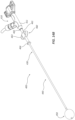
FIG. 1A is a side view of an embodiment of a bone displacement device in a ready state. -
FIG. 1B is a side view of the bone displacement device ofFIG. 1A in a bone displacement state. -
FIG. 2 is a longitudinal cross-sectional view of a proximal portion of the bone displacement device ofFIG. 1A . -
FIG. 3 is a transverse cross-sectional view of a middle portion of the bone displacement device ofFIG. 1A . -
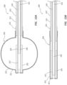
FIG. 4A is a longitudinal cross-sectional view of a distal portion of the bone displacement device ofFIG. 1A in an "expandable member expanded" state. -
FIG. 4B is a longitudinal cross-sectional view of the distal portion of the bone displacement device ofFIG. 4A , in an "expandable member not expanded" state. -
FIG. 5A is a side view of another embodiment of a bone displacement device in a ready state. -
FIG. 5B is a side view of the bone displacement device ofFIG. 5A in a bone displacement state. -
FIG. 6 is a longitudinal cross-sectional view of a proximal portion of the bone displacement device ofFIG. 5A . -
FIG. 7 is a transverse cross-sectional view of a middle portion of the bone displacement device ofFIG. 5A . -
FIG. 8A is a longitudinal cross-sectional view of a distal portion of the bone displacement device ofFIG. 5A in an "expandable member expanded" state. -
FIG. 8B is a longitudinal cross-sectional view of the distal portion of the bone displacement device ofFIG. 8A , in an "expandable member not expanded" state. -
FIG. 9A is a side view of another embodiment of a bone displacement device in a ready state. -
FIG. 9B is a side view of the bone displacement device ofFIG. 9A in a bone displacement state. -
FIG. 10 is a cross-sectional view of a proximal portion of the bone displacement device ofFIG. 9A . -
FIG. 11 is a side view of a stylet of the bone displacement device ofFIG. 9A . -
FIG. 12 is a transverse cross-sectional view of a middle portion of the bone displacement device ofFIG. 9A . -
FIG. 13A is a longitudinal cross-sectional view of a distal portion of the bone displacement device ofFIG. 9A in an "expandable member expanded" state. -
FIG. 13B is a longitudinal cross-sectional view of the distal portion of the bone displacement device ofFIG. 9A , in an "expandable member not expanded" state. -
FIG. 14A is a side view of another embodiment of a bone displacement device in a package state. -
FIG. 14B is a side view of the bone displacement device ofFIG. 14A in a ready state. - Tissue treatment devices may include elongate members, expandable members, and other components. In some instances, an elongate member of a tissue treatment device may be advanced to a treatment location and an expandable member expanded to displace tissue. For example, a bone displacement device may be disposed within a vertebra of a patient and an expandable member expanded to displace portions of the vertebra. Similarly, such devices may be utilized in other areas of the body with other types of tissue. For convenience, including when describing the illustrated embodiments, this disclosure references "bone displacement" or "bone displacement devices," however, such disclosure may be analogously applied to devices, elements, and procedures configured to displace or otherwise treat tissue in other portions of the body.
- A bone displacement device may include an elongate outer tube. A stylet may be coaxially disposed within the outer tube. A proximal portion of the outer tube and the stylet shaft may be attached to a handle. In some embodiments, the stylet comprises a plurality of pull wires coaxially disposed within a shaft of the stylet. A distal portion of the stylet may be articulated when a tension force is applied to the plurality of pull wires. In some embodiments, a portion of the handle is configured as an actuator to articulate the stylet. For example, in some embodiments, the handle comprises a rotatable grip having female threads configured to engage with male threads of a pull member. The threads may include thread stops to limit rotation of the rotatable grip. A distal portion of the plurality of pull wires is coupled to the pull member. In such embodiments, rotation of the rotatable grip in the first direction proximally displaces the pull member and thus applies a tension force to the pull wires to articulate the distal portion of the stylet. The handle may also include a side port having a valve.
- Certain bone displacement devices include an expandable member, such as a balloon. The expandable member may be disposed at a distal portion of the bone displacement device. In some embodiments, a proximal portion of the expandable member is attached to a distal portion of the outer tube via a tie layer. A distal portion of the expandable member can be attached to a tip tie tube. The tip tie tube may be longitudinally displaceable over the distal portion of the stylet. A protective sleeve may be disposed around the balloon when the bone displacement device is in its package, and displaced proximally over the outer tube to engage with the handle when the bone displacement device is ready to use.
- In certain instances, a bone displacement device may be used by a practitioner to treat a fractured bone, such as a vertebral bone. The practitioner may displace bone by inflating an expandable member at a distal end of the bone displacement device to create a cavity into which a bone stabilizing material, such as bone cement, may be injected. The rotatable grip may be rotated in a first direction to apply a tension force to pull wires to articulate a distal portion of the bone displacement device. The distal portion of the bone displacement device may be directed - via articulation of the distal portion and/or displacement of the entire bone displacement device - to a desired location within the bone. The expandable member can be expanded to displace bone tissue adjacent the expandable member to create a cavity. The bone displacement device can be removed from the bone to allow for injection of bone cement into the cavity.
- Embodiments may be understood by reference to the drawings, wherein like parts are designated by like numerals throughout. It will be readily understood by one of ordinary skill in the art having the benefit of this disclosure that the components of the embodiments, as generally described and illustrated in the figures herein, could be arranged and designed in a wide variety of different configurations. Thus, the following more detailed description of various embodiments, as represented in the figures, is not intended to limit the scope of the disclosure, but is merely representative of various embodiments. While the various aspects of the embodiments are presented in drawings, the drawings are not necessarily drawn to scale unless specifically indicated.
- It will be appreciated that various features are sometimes grouped together in a single embodiment, figure, or description thereof for the purpose of streamlining the disclosure. Many of these features may be used alone and/or in combination with one another.
- The phrases "coupled to" and "in communication with" refer to any form of interaction between two or more entities, including mechanical, electrical, magnetic, electromagnetic, fluid, and thermal interaction. Two components may be coupled to or in communication with each other even though they are not in direct contact with each other. For example, two components may be coupled to or in communication with each other through an intermediate component.
- The directional terms "distal" and "proximal" are given their ordinary meaning in the art. That is, the distal end of a medical device means the end of the device furthest from the practitioner during use. The proximal end refers to the opposite end, or the end nearest the practitioner during use. As specifically applied to a bone displacement device, the proximal end of the device refers to the end nearest the handle and the distal end refers to the opposite end, the end nearest a working tip of the device. If at one or more points in a procedure a physician changes the orientation of a bone displacement device, as used herein, the term "proximal end" always refers to the handle end of the device (even if the distal end is temporarily closer to the physician).
- "Fluid" is used in its broadest sense, to refer to any fluid, including both liquids and gases as well as solutions, compounds, suspensions, etc., which generally behave as fluids.
-
FIGS. 1A-14B illustrate different views of several bone displacement devices or osteotomes and related components. In certain views each device may be coupled to, or shown with, additional components not included in every view. Further, in some views only selected components are illustrated, to provide detail into the relationship of the components. Some components may be shown in multiple views, but not discussed in connection with every view. Disclosure provided in connection with any figure is relevant and applicable to disclosure provided in connection with any other figure or embodiment. -
FIGS. 1A-4B depict an embodiment of abone displacement device 100. In the illustrated embodiment, thebone displacement device 100 comprises ahandle 110, acatheter 130, astylet 140, and anexpandable member 150.FIG. 1A shows thebone displacement device 100 in a ready state where theexpandable member 150 is not expanded and a distal portion of thebone displacement device 100 is not articulated.FIG. 1B shows thebone displacement device 100 in a bone displacement or cavity forming state where theexpandable member 150 is expanded and the distal portion is articulated. -
FIG. 2 illustrates a proximal portion of thebone displacement device 100. The proximal portion may comprise thehandle 110, a proximal portion of thecatheter 130, and a proximal portion of thestylet 140. Thecatheter 130 may comprise an elongateouter tube 131 and an elongateinner tube 135. Theouter tube 131 may comprise aproximal portion 132. Theouter tube 131 can be formed from any suitable polymeric material. For example, theouter tube 131 may be formed from polyurethane, nylon, PBT, polyethylene, polypropylene, etc. A proximal end ofouter tube 131 can be fixedly coupled to thehandle 110. In some embodiments, theinner tube 135 is coaxially disposed within theouter tube 131. Theinner tube 135 may be formed from any of the materials listed in connection with theouter tube 131, though theinner tube 135 andouter tube 131 may or may not be formed of the same material. A proximal end of theinner tube 135 can be fixedly coupled to thehandle 110 at a location proximal of the proximal end of theouter tube 131. - In the illustrated embodiment, the
stylet 140 is shown to comprise atubular shaft 141. Theshaft 141 may be formed from any suitable rigid material, such as stainless steel, titanium, nitinol, etc. A proximal end of theshaft 141 may be fixedly coupled to thehandle 110 at a location proximal of the proximal end of theinner tube 135. One ormore pull wires 142 can be coaxially disposed within theshaft 141. In the illustrated embodiment, thepull wires 142 include a plurality of pull wires comprising seven pull wires. In other embodiments, the number ofpull wires 142 may be three, four, five, six, eight, or more pull wires. Thepull wires 142 may extend proximally from theshaft 141 and be fixedly coupled to the distal end of theshaft 141. Thepull wires 142 may be formed from any suitable material with high tensile strength. For example, thepull wires 142 may be formed from stainless steel, titanium, nitinol, etc. A diameter of thepull wires 142 may range from about 0.005 inch to about 0.030 inch. -
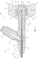
FIG. 3 illustrates a transverse cross-section of a middle portion of thebone displacement device 100. As illustrated, theouter tube 131 includes anouter lumen 134. Theinner tube 135 is shown to be coaxially disposed within theouter lumen 134. Anannular space 139 may be formed between theouter tube 131 and theinner tube 135. Theinner tube 135 may include aninner lumen 138. Theshaft 141 may be coaxially disposed within theinner lumen 138. Theshaft 141 is shown to include ashaft lumen 143. Thepull wires 142 are disposed within theshaft lumen 143. As depicted inFIG. 3 , thepull wires 142 collectively include sevenindividual pull wires 148. Theindividual pull wires 148 are disposed with a firstindividual pull wire 148 centrally located and the remaining sixindividual pull wires 148 equally spaced around the firstindividual pull wire 148. Thepull wires 148 are shown as individual strands disposed longitudinally adjacent each other (without braiding or twisting) in the illustrated embodiment. This configuration of thepull wires 148 may be configured to provide adequate stiffness to thebone displacement device 100 to the ready state where the distal portion of thebone displacement device 100 is not articulated and/or to facilitate transfer of force to straighten thebone displacement device 100 from an articulated configuration to a non articulated configuration. In another embodiment, eachpull wire 148 may be formed in a braid of a plurality of smaller diameter wires. Other arrangements of thepull wires 148 are likewise within the scope of this disclosure, including embodiments where the individual wires are braided or twisted into a cable. - Referring again to
FIG. 2 , thehandle 110 may comprise abody 111 and arotatable grip 112 rotatably coupled to a proximal end of thebody 111. Thebody 111 androtatable grip 112 may be formed from any suitable polymeric material, such as polycarbonate, acrylonitrile butadiene styrene, etc. Thebody 111 may comprise aside port 124. In the illustrated embodiment, theside port 124 extends generally proximally and laterally from a longitudinal axis of thebody 111. Theside port 124 may extend at an angle ranging from 15 degrees to 90 degrees or about 45 degrees relative to the longitudinal axis. Theside port 124 may be in fluid communication with the annular space (139 ofFIG. 3 .) During some therapies, a fluid delivery device (e.g., syringe) can be releasably coupled to a proximal portion of theside port 124. Avalve member 122 may be disposed within theside port 124. Thevalve member 122 may be configured to selectively permit air or fluid to be directed from the fluid delivery device, through theside port 124, through theannular space 139, and then to the expandable member (150 ofFIG. 1A ) when the fluid delivery device is coupled to theside port 124. Thevalve member 122 may also be configured to retain the air or fluid within theannular space 139 and theexpandable member 150 when the fluid delivery device is removed from theside port 124. - In the illustrated embodiment, the proximal end of the
outer tube 131 is coupled to thebody 111 at a location distal to theside port 124, and theinner tube 135 is coupled to thebody 111 at a location proximal to theside port 124. Further, a proximal end of theshaft 141 can be coupled to thebody 111 at a location proximal to theinner tube 135. - The
rotatable grip 112 may be configured to be rotated around a longitudinal axis of thehandle 110. As depicted, therotatable grip 112 may comprise laterally extendingwings 113 configured to be gripped by a user. In other embodiments, therotatable grip 112 may comprise any suitable feature to facilitate gripping and rotation of therotatable grip 112. For example, therotatable grip 112 may comprise a knob including grippable features, such as ridges, bumps, recesses, textured surface, etc. Therotatable grip 112 may comprise achamber 119 configured to receive apull member 116. As shown in the figures, and discussed below, thepull member 116 of the illustrated embodiment is configured as non-rotatable relative to therotatable grip 112, or configured not to rotate with therotatable grip 112. Thechamber 119 may include afemale thread 114 configured to engage amale thread 117 of thepull member 116. Thefemale thread 114 may comprise proximal and distal female thread stops 115. In the illustrated embodiment, the female thread stops 115 may include a flat face oriented perpendicular to a longitudinal axis of therotatable grip 112. In another embodiment, the female thread stops 115 may include a tapered face. Thepull member 116 may include amale thread 117 configured to engage with thefemale thread 114. Themale thread 117 may comprise proximal and distal male thread stops 118. In the illustrated embodiment, the male thread stops 118 may include a flat face oriented perpendicular to a longitudinal axis of thepull member 116. In another embodiment, the male thread stops 118 may include a tapered face. The female thread stops 115 can be configured to engage with the male thread stops 118 to prevent over-rotation of therotatable grip 112 in both a first direction and a second direction. In some instances, over-rotation of therotatable grip 112 may result in excess strain or breakage of theshaft 141 and/or one or more of theindividual pull wires 148. Thus, the threads may be configured with a positive stop to minimize excess force and subsequent breakage. In another embodiment, thechamber 119 may include amale thread 117 and male thread stops 118 while thepull member 116 includes afemale thread 114 and female thread stops 115. - In the illustrated embodiment, the proximal ends of the
pull wires 142 may be fixedly coupled to thepull member 116. When therotatable grip 112 is rotated in the first direction, thepull member 116 is displaced proximally, causing a tension force to be equally or substantially equally applied to all of theindividual pull wires 148. Embodiments wherein one or moreindividual pull wires 148 transmit an uneven or larger portion of the tension force are likewise within the scope of this disclosure. The tension force on thepull wires 142 may result in a tension force being applied to the distal end of thestylet 140 and articulation of the distal portion of thebone displacement device 100, as shown inFIG. 1B . During actuation, therotatable grip 112 may be rotated from about one degree to about 540 degrees, from about one degree to about 360 degrees, or from about one degree to about 180 degrees, or along any portion of these ranges. Rotation of therotatable grip 112 in the first direction may be stopped when the proximalfemale thread stop 115 engages with the proximalmale thread stop 118, or may be stopped at any point along the range of rotation of therotatable grip 112, meaning it is stopped by a user at a point of partial rotation along the rotational range of therotatable grip 112. Rotation of therotatable grip 112 and proximal displacement of thepull member 116 may result in an articulation of the distal portion of thebone displacement device 100 from about zero degrees to about 180 degrees, from about zero degrees to about 135 degrees, or from about zero degrees to about 90 degrees. In some embodiments, therotatable grip 112 may comprise a rotation lock configured to maintain therotatable grip 112 in a partial or fully rotated state when therotatable grip 112 is released by the user. For example, thebody 111 may comprise teeth configured to engage with opposing teeth of therotatable grip 112. - Rotation of the
rotatable grip 112 in the second direction may displace thepull member 116 distally and release the tension force on thepull wires 142, resulting in the distal portion of thebone displacement device 100 returning to a straight configuration, as shown inFIG. 1A . Therotatable grip 112 can be rotated in the second direction until the distalfemale thread stop 115 engages with the distalmale thread stop 118. -
FIGS. 4A-4B illustrate a distal portion of thebone displacement device 100. The distal portion may comprise theexpandable member 150, adistal portion 133 of theouter tube 131, adistal portion 137 of theinner tube 135, and adistal portion 145 of theshaft 141. Theinner tube 135 and theshaft 141 may extend beyond a distal end of theouter tube 131. Theinner tube 135 may extend beyond a distal end of theshaft 141. In the illustrated embodiment, theexpandable member 150 comprises aballoon 151. In other embodiments, theexpandable member 150 may comprise any suitable expandable and retractable mechanism. For example, theexpandable member 150 may comprise a plurality of ribs configured to expand radially outward. - The
balloon 151 may comprise adouble balloon wall 152 configured to expand radially outward without stretching when air or fluid is injected into theballoon 151, for example, through theannular space 139. Embodiments wherein the balloon wall comprises more or fewer layers are likewise within the scope of this disclosure. A thickness of thedouble balloon wall 152 may range from about 0.020 mm to about 0.038 mm or from about .025 mm to about 0.030 mm. A length of theballoon 151 when not inflated or expanded may range from about 10 mm to about 30 mm. Theballoon 151 may be formed of any suitable non-compliant polymeric material, such as engineered plastic polyurethane (e.g., Isoplast®), nylon, polybutylene terephthalate, etc. A proximal portion of theballoon 151 may be sealingly coupled to the distal end of theouter tube 131. Atie layer 153 may be disposed between theballoon wall 152 and theouter tube 131 to facilitate bonding of theballoon wall 152 to theouter tube 131. In other embodiments, thetie layer 153 is not used to facilitate bonding of theballoon wall 152 to theouter tube 131. Thetie layer 153 may be formed from a polyurethane material having an intermediate hardness that is between the hardness of the material of theballoon 151 and the hardness of the material of theouter tube 131. Theballoon wall 152 may be bonded to thetie layer 153 and theouter tube 131 using any suitable technique, such as heat, radio frequency, solvent bonding, gluing, etc. - A distal portion of the
balloon 151 may be sealingly coupled to the distal end of theinner tube 135. Atip tie tube 155 may be disposed between theballoon wall 152 and theinner tube 135. Thetip tie tube 155 may be formed from a material similar to thetie layer 153. In some embodiments, thetip tie tube 155 may comprise a braided structure. Thetip tie tube 155 may extend proximally over thedistal portion 137 of theinner tube 135 and thedistal portion 145 of theshaft 141. Thetip tie tube 155 andshaft 141 may configured in a "piston/cylinder" type arrangements where theshaft 141 is allowed to move with respect to the tip tie tube when theballoon 151 is inflated or deflated. For example, thetip tie tube 155 may be configured to piston proximally over theshaft 141 when theballoon 151 is inflated and to piston distally over theshaft 141 when theballoon 151 is deflated. Thetip tie tube 155 may be configured to facilitate bonding of theballoon wall 152 to theinner tube 135. In other embodiments, thetip tie tube 155 may provide structural support to theinner tube 135 to prevent kinking of theinner tube 135 when inserted into a vertebral bone. - The seal of the proximal end of the
balloon 151 to theouter tube 131 and the seal of the distal end of theballoon 151 to theinner tube 135 may form aballoon chamber 156 configured to be pressurized. Theballoon chamber 156 may be pressurized up to a pressure of about 60 atm. Theballoon 151 may be expanded to a diameter of from about 10 mm to about 30 mm. - As shown in
FIGS. 4A-4B , thedistal portion 145 of theshaft 141 may comprise a plurality of laser cuts 147. The laser cuts 147 may facilitate articulation of theshaft 141 in a single plane when the tension force is applied to thepull wires 142, as shown inFIG 1B . The laser cuts 147 may comprise variables (e.g., depth, pitch, spacing) that control the articulation parameters of theshaft 141, such as angle of articulation. In certain embodiments, the laser cuts 147 may comprise a tab configured to be received by a recess. The laser cuts 147 of this embodiment may prevent torsional rotation of the laser cuts 147 relative to one another. Thepull wires 142 may also prevent torsional rotation of thelaser cuts 147 because thepull wires 142 substantially fill theshaft lumen 143 preventing axial misalignment of the laser cuts 147. The laser cuts 147 may extend partially through a diameter of theshaft 141, leaving a spine of uncut material. When articulated, theshaft 141 may bend toward the spine while a distance between shaft segments on either side of the laser cuts 147 increases on an opposing side of theshaft 141, defining a substantially "V" shape. - During use, in some instances, the
shaft 141 may break at one of thelaser cuts 147 when theshaft 141 is articulated. This may be due to external forces (such as from the bone) acting on theshaft 141. In the event of a breakage, thepull wires 142 may prevent a portion of theshaft 141 distal to the break from breaking away from a remainder of theshaft 141. Even if one of theindividual pull wires 148 also breaks, the remainingindividual pull wires 148 may retain attachment to the distal end of theshaft 141. Furthermore, embodiments wherein thepull wires 142 collectively fill theshaft lumen 143, even in an event of a break in theshaft 141, thepull wires 142 may maintain the coaxial arrangement of theshaft 141,inner tube 135, andouter tube 131 and prevent leakage of air or fluid from thebone displacement device 100 caused by damage to theinner tube 135 and/orouter tube 131 by a broken end of theshaft 141 of apull wire 148 . - In use, a bone displacement device may be used to displace bone tissue. A distal end of the bone displacement device may be inserted into a vertebral bone, for example, through an introducer cannula. A distal portion of the bone displacement device may be articulated when a rotatable grip is rotated in a first direction, causing one or more pull members to be displaced proximally. Proximal displacement of the pull member may apply a tension force to pull wires disposed within a stylet shaft and coupled to the pull member. The tension force applied to the pull wires can cause a distal portion of a stylet to articulate the distal portion of the bone displacement device. The articulated bone displacement device can be directed to a desired location within the vertebral bone. A syringe may be coupled to a side port of a handle. Air or fluid may be delivered through the side port to an expandable member (e.g., balloon) disposed adjacent the distal end of the bone displacement device. The air or fluid may expand the expandable member to displace adjacent bone tissue.
-
FIGS. 5A-8B depict an embodiment of abone displacement device 200 that resembles thebone displacement device 100 described above in certain respects. Accordingly, like features are designated with like reference numerals, with the leading digit incremented to "2." For example, the embodiment depicted inFIGS. 5A-8B includes ahandle 210 that may, in some respects, resemble thehandle 110 ofFIG. 1A . Relevant disclosure set forth above regarding similarly identified features thus may not be repeated hereafter. Moreover, specific features of thebone displacement device 100 and related components shown inFIGS. 1A-4A may not be shown or identified by a reference numeral in the drawings or specifically discussed in the written description that follows. However, such features may clearly be the same, or substantially the same, as features depicted in other embodiments and/or described with respect to such embodiments. Accordingly, the relevant descriptions of such features apply equally to the features of thebone displacement device 200 and related components depicted inFIGS. 5A-8B . Any suitable combination of the features, and variations of the same, described with respect to thebone displacement device 100 and related components illustrated inFIGS. 1A-4B can be employed with thebone displacement device 200 and related components ofFIGS. 5A-8B , and vice versa. This pattern of disclosure applies equally to further embodiments depicted in subsequent figures and described hereafter, wherein the leading digits may be further incremented. -
FIGS. 5A-8B depict another embodiment of abone displacement device 200. In the illustrated embodiment ofFIGS. 5A-8B , thebone displacement device 200 comprises ahandle 210, acatheter 230, astylet 240, and anexpandable member 250.FIG. 5A shows thebone displacement device 200 in a ready state where theexpandable member 250 is not expanded and a distal portion of thebone displacement device 200 is substantially straight.FIG. 5B shows thebone displacement device 200 in a cavity forming state where theexpandable member 250 is expanded and the distal portion is articulated. -
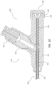
FIG. 6 illustrates a proximal portion of thebone displacement device 200. The proximal portion may comprise thehandle 210, a proximal portion of thecatheter 230, and a proximal portion of thestylet 240. Thecatheter 230 may comprise an elongateouter tube 231 having aproximal portion 232. A proximal end of theouter tube 231 can be fixedly coupled to thehandle 210. - The
stylet 240 is shown to comprise atubular shaft 241 having aproximal portion 244. A proximal end of theshaft 241 may be fixedly coupled to thehandle 210 at a location proximal of the proximal end of theouter tube 231. One ormore pull wires 242 can be disposed within theshaft 241. -
FIG. 7 illustrates a transverse cross-section of a middle portion of thebone displacement device 200. As illustrated, theouter tube 231 includes anouter lumen 234. Theshaft 241 may be coaxially disposed within theouter lumen 234. Anannular space 239 may be formed between theouter tube 231 and theshaft 241. Theshaft 241 may include ashaft lumen 243. Thepull wires 242 can be disposed within theshaft lumen 243. - Referring again to
FIG. 6 , thehandle 210 may comprise abody 211 and arotatable grip 212 rotatably coupled to a proximal end of thebody 211. Thebody 211 may comprise aside port 224 extending laterally from a longitudinal axis of thebody 211. Theside port 224 may be in fluid communication with the annular space (239 ofFIG. 7 ). A fluid delivery device (e.g., syringe) can be releasably coupled to a proximal portion of theside port 224. Avalve member 222 may be disposed within theside port 124. Thevalve member 222 may be configured to selectively permit air or fluid to be directed through theside port 224, through theannular space 239, and to theexpandable member 250 when the fluid delivery device is coupled to theside port 224. Thevalve member 222 may also be configured to retain the air or fluid within theannular space 239 and theexpandable member 250 when the fluid delivery device is removed from theside port 224. - In the illustrated embodiment, the proximal end of the
outer tube 231 can be coupled to thebody 211 at a location distal to theside port 224. Theshaft 241 can be coupled to thebody 211 at a location proximal to theouter tube 231. - The
rotatable grip 212 may be configured to be rotatable around a longitudinal axis of thehandle 210. Therotatable grip 212 may comprise generally laterally and proximally extendingwings 213 configured to be gripped by a user. Therotatable grip 212 may comprise achamber 219 configured to receive apull member 216. Thechamber 219 may include afemale thread 214 configured to engage amale thread 217 of thepull member 216. Thefemale thread 214 may comprise proximal and distal thread stops 215. Themale thread 217 may comprise proximal and distal thread stops 218. The female thread stops 215 can be configured to engage with the male thread stops 218 to prevent over-rotation of therotatable grip 212 in both a first direction and a second direction. - In the illustrated embodiment, the proximal ends of the
pull wires 242 may be fixedly coupled to thepull member 216. When therotatable grip 212 is rotated in the first direction, thepull member 216 can be displaced proximally, causing a tension force to be applied to thepull wires 242. The tension force on thepull wires 242 may result in a tension force being applied to the distal end of theshaft 241 and articulation of theshaft 241 and thebone displacement device 200, as shown inFIG. 5B . - Rotation of the
rotatable grip 212 in the second direction may displace thepull member 216 distally and release the tension force on thepull wires 242, resulting in the distal portion of thebone displacement device 200 returning to a substantially straight configuration, as shown inFIG. 5A . Therotatable grip 212 can be rotated in the second direction until the distalfemale thread stop 215 engages with the distalmale thread stop 218. -
FIGS. 8A-8B illustrate a distal portion of thebone displacement device 200. The distal portion may comprise anexpandable member 250, adistal portion 233 of theouter tube 231, and adistal portion 245 of theshaft 241. Theshaft 241 may extend beyond the distal end of theouter tube 231. In the illustrated embodiment, theexpandable member 250 comprises aballoon 251. - The
balloon 251 may comprise a balloon wall, such as adouble balloon wall 252 configured to expand radially outward without stretching when air or fluid is injected into theballoon 251 through theannular space 239. A proximal portion of theballoon 251 may be sealingly coupled to the distal end of theouter tube 231. Atie layer 253 may be disposed between theballoon wall 252 and theouter tube 231 to facilitate bonding of theballoon wall 252 to theouter tube 231. - A distal portion of the
balloon 251 may be sealingly coupled to a distal end of atip tie tube 255. Thetip tie tube 255 may extend proximally over thedistal portion 245 of theshaft 241. Thetip tie tube 255 andshaft 241 may configured in a "piston/cylinder" type arrangements where theshaft 214 is allowed to move with respect to the tip tie tube when theballoon 251 is inflated or deflated. For example, thetip tie tube 255 may be configured to piston proximally over theshaft 241 when theballoon 251 is inflated and to piston distally over theshaft 241 when theballoon 251 is deflated. Aplug 254 may be sealingly disposed within the distal end of thetip tie tube 255. - The seal of the proximal end of the
balloon 251 to theouter tube 231 and the seal of the distal end of theballoon 251 to thetip tie tube 255 may form aballoon chamber 256 configured to be pressurized. Theballoon chamber 256 may be pressurized up to a pressure of about 60 atm. Theballoon 251 may be expanded to a diameter of from about 10 mm to about 30 mm. - As shown in
FIGS. 8A-8B , the distal portion of theshaft 241 may comprise a plurality of laser cuts 247. The laser cuts 247 may facilitate articulation of theshaft 241 when the tension force is applied to thepull wires 242, as shown inFIG 8B . -
FIGS. 9A-13B depict another embodiment of abone displacement device 300. In the illustrated embodiment, thebone displacement device 300 is partially composed of ahandle 310, acatheter 330, astylet 340, and anexpandable member 350.FIG. 9A shows thebone displacement device 300 in a ready state where theexpandable member 350 is not expanded and a distal portion of thebone displacement device 300 is substantially straight.FIG. 9B shows thebone displacement device 300 in a cavity forming state where theexpandable member 350 is expanded and the distal portion is substantially straight. -
FIG. 10 illustrates a proximal portion of thebone displacement device 300. The proximal portion may comprise thehandle 310, a proximal portion of thecatheter 330, and a proximal portion of thestylet 340. Thecatheter 330 may comprise an elongateouter tube 331 and an elongateinner tube 335. A proximal end ofouter tube 331 can be coupled to thehandle 310. Theinner tube 335 may be coaxially disposed within theouter tube 331. A proximal end of theinner tube 335 can be coupled to thehandle 310 at a location proximal of the proximal end of theouter tube 331. - The
handle 310 may comprise abody 311. Thebody 311 may comprise aside port 324 extending laterally from a longitudinal axis of thebody 311. Theside port 324 may be in fluid communication with an annular space (339 ofFIG. 12 ). A fluid delivery device (e.g., syringe) can be releasably coupled to a proximal portion of theside port 324. Avalve member 322 may be disposed within theside port 324. Thevalve member 322 may be configured to selectively permit air or fluid to be directed through theside port 324, through theannular space 339, and to theexpandable member 350 when the fluid delivery device is coupled to theside port 324. Thevalve member 322 may also be configured to retain the air or fluid within theannular space 339 and theexpandable member 350 when the fluid delivery device is removed from theside port 324. Thebody 311 may include aproximal port 325 in fluid communication with theinner tube 335. Theproximal port 325 may be configured to receive thestylet 340. In one embodiment, theproximal port 325 may include a female luer taper and a thread engagement feature. - In the illustrated embodiment, the proximal end of the
outer tube 331 can be coupled to thebody 311 at a location distal to theside port 324. Theinner tube 335 can be coupled to thebody 311 at a location proximal to theouter tube 331. -
FIG. 11 depicts thestylet 340. Thestylet 340 may comprise ashaft 341 and aconnector 348. Theshaft 341 may be a cylindrical rod. In other embodiments, theshaft 341 may be a cylindrical tube. A proximal end of theshaft 341 may be fixedly coupled to theconnector 348. In the illustrated embodiment, theconnector 348 is a male luer nut. Theconnector 348 may be configured to be removably coupled to theproximal port 325 such that thestylet 340 may be inserted into and removed from thebone displacement device 300 through theproximal port 325. -
FIG. 12 illustrates a transverse cross-section of a middle portion of thebone displacement device 300. As illustrated, theouter tube 331 includes anouter lumen 334. Theinner tube 335 is shown to be coaxially disposed within theouter lumen 334. Anannular space 339 may be defined between theouter tube 331 and theinner tube 335. The inner tube may include aninner lumen 338. Theshaft 341 may be coaxially disposed within theinner lumen 338. -
FIGS. 13A-13B illustrate a distal portion of thebone displacement device 300. The distal portion may comprise anexpandable member 350, adistal portion 333 of theouter tube 331, adistal portion 337 of theinner tube 335, and adistal portion 345 of theshaft 341. Theinner tube 335 and theshaft 341 may extend beyond the distal end of theouter tube 331. Theinner tube 335 may extend beyond the distal end of theshaft 341. In the illustrated embodiment, theexpandable member 350 comprises aballoon 351. - A proximal portion of the
balloon 351 may be sealingly coupled to the distal end of theouter tube 331. Atie layer 353 may be disposed between aballoon wall 352 and theouter tube 331 to facilitate bonding of theballoon wall 352 to theouter tube 331. A distal portion of theballoon 351 may be sealingly coupled to the distal end of theinner tube 335. Atip tie tube 355 may be disposed between theballoon wall 352 and theinner tube 335. Thetip tie tube 355 may extend proximally over thedistal portion 337 of theinner tube 335 and thedistal portion 345 of theshaft 341. Thetip tie tube 355 andshaft 341 may be configured to move in a piston/cylinder configuration when theballoon 351 is inflated and deflated. For example, thetip tie tube 335 may move proximally over theshaft 341 when theballoon 351 is inflated, as shown inFIG. 13A , and to piston distally over theshaft 341 when theballoon 351 is deflated, as shown inFIG. 13B . -
FIGS. 14A-14B depict another embodiment of abone displacement device 400. In the illustrated embodiment, thebone displacement device 400 comprises ahandle 410, acatheter 430, astylet 440, anexpandable member 450, and aprotective sleeve 460.FIG. 14A shows thebone displacement device 400 in a package state where theprotective sleeve 460 surrounds theexpandable member 450.FIG. 14B shows thebone displacement device 400 in a ready state where theprotective sleeve 460 is displaced proximally over thecatheter 430 and releasably coupled to thehandle 410. - In the depicted embodiment, the
protective sleeve 460 may include atubular body 461 and agrip 463 coupled to thetubular body 461. Adistal end 464 of thetubular body 461 may be formed in a funnel shape to facilitate passage of theprotective sleeve 460 distally over theexpandable member 450 when not expanded. A proximal end of thetubular body 461 may be sized to be releasably received into arecess 465 disposed at a distal end of abody 411 of thehandle 410, as shown inFIG. 14B . In other embodiments, the proximal end of thetubular body 461 may be sized to fit over a protrusion extending from the distal end of thebody 411. - As depicted in the illustrated embodiment, the
grip 463 has an oval shape. In other embodiments, thegrip 463 may have any suitable shape that is grippable with fingers of a user. For example, thegrip 463 may have a rectangular, square, circular, or triangular shape, etc. In some embodiments, thegrip 463 may include grip enhancing features, such as ridges, bumps, recesses, etc. In another embodiment, thegrip 463 may include indicia (e.g., an arrow) to indicate the direction theprotective sleeve 460 could be moved prior to use of thebone displacement device 400. - The
protective sleeve 460 may be disposed over theexpandable member 450 during a manufacturing assembly of and prior to packaging of thebone displacement device 400. In preparation for a treatment procedure, a user can remove thebone displacement device 400 from its package in the package state, as shown inFIG. 14A , where theprotective sleeve 460 is disposed over theexpandable member 450. The user may then proximally displace theprotective sleeve 460 and releaseably couple theprotective sleeve 460 to thehandle 410, as shown inFIG. 14B , prior to insertion of thebone displacement device 400 into a vertebral bone of a patient to prevent theprotective sleeve 460 from inadvertent distal displacement into a working field . In some procedures, upon removal of thebone displacement device 400 from the vertebral bone, the user may longitudinally distally displace theprotective sleeve 460 to rewrap (e.g., radially compress) theexpandable member 450 in preparation for re-insertion of thebone displacement device 400. - Any methods disclosed herein comprise one or more steps or actions for performing the described method. The method steps and/or actions may be interchanged with one another. In other words, unless a specific order of steps or actions is required for proper operation of the embodiment, the order and/or use of specific steps and/or actions may be modified.
- References to approximations are made throughout this specification, such as by use of the term "substantially." For each such reference, it is to be understood that, in some embodiments, the value, feature, or characteristic may be specified without approximation. For example, where qualifiers such as "about" and "substantially" are used, these terms include within their scope the qualified words in the absence of their qualifiers. For example, where the term "substantially perpendicular" is recited with respect to a feature, it is understood that in further embodiments, the feature can have a precisely perpendicular configuration.
- Similarly, in the above description of embodiments, various features are sometimes grouped together in a single embodiment, figure, or description thereof for the purpose of streamlining the disclosure. This method of disclosure, however, is not to be interpreted as reflecting an intention that any claim require more features than those expressly recited in that claim. Rather, as the following claims reflect, inventive aspects lie in a combination of fewer than all features of any single foregoing disclosed embodiment.
- The claims following this written disclosure are hereby expressly incorporated into the present written disclosure, with each claim standing on its own as a separate embodiment. This disclosure includes all permutations of the independent claims with their dependent claims. Moreover, additional embodiments capable of derivation from the independent and dependent claims that follow are also expressly incorporated into the present written description.
- Without further elaboration, it is believed that one skilled in the art can use the preceding description to utilize the invention to its fullest extent. The claims and embodiments disclosed herein are to be construed as merely illustrative and exemplary, and not a limitation of the scope of the present disclosure in any way. It will be apparent to those having ordinary skill in the art, with the aid of the present disclosure, that changes may be made to the details of the above-described embodiments without departing from the underlying principles of the disclosure herein. In other words, various modifications and improvements of the embodiments specifically disclosed in the description above are within the scope of the appended claims. Moreover, the order of the steps or actions of the methods disclosed herein may be changed by those skilled in the art without departing from the scope of the present disclosure. In other words, unless a specific order of steps or actions is required for proper operation of the embodiment, the order or use of specific steps or actions may be modified. The scope of the invention is therefore defined by the following claims and their equivalents.
- Further aspects of the invention are disclosed in the following numbered statements:
- Statement 1. A bone displacement device, comprising:
- an elongate outer tube;
- an elongate stylet coaxially disposed within the outer tube, wherein the stylet comprises a tubular shaft and a plurality of pull wires disposed within the shaft;
- a handle coupled to a proximal portion of the outer tube and the stylet; and
- an expandable member disposed adjacent a distal end of the outer tube.
-
Statement 2. The bone displacement device of statement 1, wherein the stylet comprises seven pull wires. - Statement 3. The bone displacement device of statement 1 or
statement 2, wherein the handle comprises a rotatable grip, and wherein the plurality of pull wires are coupled to a pull member disposed within the rotatable grip. - Statement 4. The bone displacement device of statement 3, wherein the pull member comprises male threads configured to engage with female threads of the rotatable grip.
- Statement 5. The bone displacement device of statement 3 or statement 4, wherein the pull member is displaced proximally when the rotatable grip is rotated in a first direction to apply a tension force to the plurality of pull wires, and displaced distally when the rotatable grip is rotated in a second direction to release the tension force from the plurality of pull wires, and wherein a distal portion of the stylet articulates when the tension force is applied to the plurality of pull wires.
- Statement 6. The bone displacement device of statement 4,
- wherein the male threads comprise a proximal male thread stop and a distal male thread stop;
- wherein the female threads comprise a proximal female thread stop and a distal female thread stop;
- wherein the proximal male thread stop is configured to engage with the proximal female thread stop to limit proximal displacement of the pull member; and
- wherein the distal male thread stop is configured to engage with the distal female thread stop to limit distal displacement of the pull member.
- Statement 7. The bone displacement device of any one of statements 1-6, further comprising a tip tie tube coupled to a distal end of the expandable member and slidably disposed over a distal portion of the stylet, wherein the tip tie tube is displaced proximally relative to the distal portion of the stylet when the expandable member is expanded, and is displaced distally relative to the distal portion of the stylet when the expandable member is contracted.
- Statement 8. The bone displacement device of statement 7, wherein the tip tie tube comprises a braided material.
- Statement 9. The bone displacement device of any one of statements 1-8, further comprising an elongate inner tube coaxially disposed between the outer tube and the stylet.
-
Statement 10. The bone displacement device of statement 9, wherein a proximal portion of the expandable member is sealingly coupled to a tie layer, and the tie layer is sealingly coupled to a distal portion of the outer tube, and wherein a distal portion of the expandable member is sealingly coupled to the tip tie tube, and the tip tie tube is sealingly coupled to a distal portion of the inner tube. - Statement 11. The bone displacement device of any one of statements 1-10, wherein the expandable member is a balloon.
-
Statement 12. The bone displacement device of any one of statements 1-11, wherein the handle comprises a side port and a valve member disposed within the side port. - Statement 13. A bone displacement system, comprising:
- a bone displacement device, comprising:
- an elongate outer tube;
- an elongate stylet coaxially disposed within the outer tube, wherein the stylet comprises a tubular shaft and a plurality of pull wires disposed within the shaft;
- a handle coupled to a proximal end of the outer tube and the stylet; and
- an expandable member disposed adjacent a distal end of the outer tube; and
- a protective sleeve configured to be slidably displaceable over the outer tube.
- a bone displacement device, comprising:
- Statement 14. The bone displacement system of statement 13, wherein the stylet comprises seven pull wires.
- Statement 15. The bone displacement system of statement 13 or 14, wherein the protective sleeve comprises a tubular member and a grip coupled to the tubular member.
- Statement 16. The bone displacement system of any one of statements 13-15, wherein the protective sleeve is disposed around the expandable member when the bone displacement device is in a package state, and is coupled to the handle when the bone displacement device is in a ready state.
- Statement 17. A method of displacing bone, comprising:
- obtaining a bone displacement device, comprising:
- an elongate outer tube;
- an elongate stylet coaxially disposed within the outer tube, wherein the stylet comprises a tubular shaft and a plurality of pull wires disposed within the shaft;
- a handle coupled to a proximal end of the outer tube and the stylet; and
- an expandable member disposed adjacent a distal end of the outer tube;
- inserting a distal portion of the bone displacement device into a bone;
- articulating a distal portion of the stylet; and
- expanding the expandable member.
- obtaining a bone displacement device, comprising:
- Statement 18. The method of statement 17, wherein the articulating the distal portion of the stylet comprises rotating a rotatable grip in a first direction, wherein a tension force is applied to the plurality of pull wires.
- Statement 19. The method of statement 17 or statement 18, wherein the bone displacement device further comprises a protective sleeve.
- Statement 20. The method of statement 19, further comprising displacing the protective sleeve proximally from a bone displacement device package state where the protective sleeve surrounds the expandable member to a bone displacement device ready state where the protective sleeve is coupled to the handle.
Claims (15)
- A bone displacement system, comprising:a bone displacement device, comprising:an elongate outer tube;an elongate stylet coaxially disposed within the outer tube, wherein the stylet comprises a tubular shaft;a handle coupled to a proximal portion of the outer tube and the stylet; andan expandable member disposed adjacent a distal end of the outer tube; anda protective sleeve configured to be slidably displaceable over the outer tube.
- The bone displacement system of claim 1, wherein the stylet comprises a plurality of pull wires disposed within the shaft.
- The bone displacement system of claim 1 or claim 2, wherein the protective sleeve comprises a tubular member and a grip coupled to the tubular member.
- The bone displacement system of any one of claims 1-3, wherein the protective sleeve is disposed around the expandable member when the bone displacement device is in a package state, and is coupled to the handle when the bone displacement device is in a ready state.
- The bone displacement system of any one of claim 1-4, further comprising a tip tie tube coupled to a distal end of the expandable member and slidably disposed over a distal portion of the stylet.
- The bone displacement system of claim 5, wherein the tip tie tube is displaced proximally relative to the distal portion of the stylet when the expandable member is expanded, and is displaced distally relative to the distal portion of the stylet when the expandable member is contracted.
- The bone displacement system of claim 5 or claim 6, wherein the tip tie tube comprises a braided material.
- The bone displacement system of any one of claims 1-7, further comprising an elongate inner tube coaxially disposed between the outer tube and the stylet.
- The bone displacement system of claim 9, wherein a proximal portion of the expandable member is sealingly coupled to a tie layer, and the tie layer is sealingly coupled to a distal portion of the outer tube, and wherein a distal portion of the expandable member is sealingly coupled to the tip tie tube, and the tip tie tube is sealingly coupled to a distal portion of the inner tube.
- The bone displacement system of any one of claims 1-9, wherein the expandable member is a balloon.
- The bone displacement system of any one of claims 1-10, wherein the handle comprises a side port and a valve member disposed within the side port.
- The bone displacement system of claim 2, wherein the stylet comprises seven pull wires.
- The bone displacement system of claim 2 or claim 12, wherein the handle comprises a rotatable grip, and wherein the plurality of pull wires are coupled to a pull member disposed within the rotatable grip.
- The bone displacement system of claim 13, wherein the pull member comprises male threads configured to engage with female threads of the rotatable grip.
- The bone displacement system of claim 13 or claim 14, wherein the pull member is displaced proximally when the rotatable grip is rotated in a first direction to apply a tension force to the plurality of pull wires, and displaced distally when the rotatable grip is rotated in a second direction to release the tension force from the plurality of pull wires, and wherein a distal portion of the stylet articulates when the tension force is applied to the plurality of pull wires.
Applications Claiming Priority (3)
| Application Number | Priority Date | Filing Date | Title |
|---|---|---|---|
| US201962902144P | 2019-09-18 | 2019-09-18 | |
| EP20865049.9A EP4031040B1 (en) | 2019-09-18 | 2020-09-17 | Osteotome with inflatable portion and multiwire articulation |
| PCT/US2020/051288 WO2021055617A1 (en) | 2019-09-18 | 2020-09-17 | Osteotome with inflatable portion and multiwire articulation |
Related Parent Applications (2)
| Application Number | Title | Priority Date | Filing Date |
|---|---|---|---|
| EP20865049.9A Division EP4031040B1 (en) | 2019-09-18 | 2020-09-17 | Osteotome with inflatable portion and multiwire articulation |
| EP20865049.9A Division-Into EP4031040B1 (en) | 2019-09-18 | 2020-09-17 | Osteotome with inflatable portion and multiwire articulation |
Publications (2)
| Publication Number | Publication Date |
|---|---|
| EP4574195A2 true EP4574195A2 (en) | 2025-06-25 |
| EP4574195A3 EP4574195A3 (en) | 2025-08-27 |
Family
ID=74869120
Family Applications (2)
| Application Number | Title | Priority Date | Filing Date |
|---|---|---|---|
| EP25161660.3A Pending EP4574195A3 (en) | 2019-09-18 | 2020-09-17 | Osteotome with inflatable portion and multiwire articulation |
| EP20865049.9A Active EP4031040B1 (en) | 2019-09-18 | 2020-09-17 | Osteotome with inflatable portion and multiwire articulation |
Family Applications After (1)
| Application Number | Title | Priority Date | Filing Date |
|---|---|---|---|
| EP20865049.9A Active EP4031040B1 (en) | 2019-09-18 | 2020-09-17 | Osteotome with inflatable portion and multiwire articulation |
Country Status (3)
| Country | Link |
|---|---|
| US (2) | US11986229B2 (en) |
| EP (2) | EP4574195A3 (en) |
| WO (1) | WO2021055617A1 (en) |
Families Citing this family (8)
| Publication number | Priority date | Publication date | Assignee | Title |
|---|---|---|---|---|
| US10390877B2 (en) | 2011-12-30 | 2019-08-27 | Relievant Medsystems, Inc. | Systems and methods for treating back pain |
| AU2013337680B2 (en) | 2012-11-05 | 2019-04-18 | Relievant Medsystems, Inc. | Systems and methods for creating curved paths through bone and modulating nerves within the bone |
| WO2021050767A1 (en) | 2019-09-12 | 2021-03-18 | Relievant Medsystems, Inc. | Systems and methods for tissue modulation |
| US11986229B2 (en) * | 2019-09-18 | 2024-05-21 | Merit Medical Systems, Inc. | Osteotome with inflatable portion and multiwire articulation |
| AU2021306313A1 (en) | 2020-07-10 | 2023-03-02 | Relievant Medsystems, Inc. | Vertebral denervation in conjunction with vertebral fusion |
| US12082876B1 (en) | 2020-09-28 | 2024-09-10 | Relievant Medsystems, Inc. | Introducer drill |
| EP4268150A4 (en) | 2020-12-22 | 2024-12-18 | Relievant Medsystems, Inc. | PREDICTION OF CANDIDATES FOR SPINAL NEUROMODULATION |
| US12433668B1 (en) | 2021-11-08 | 2025-10-07 | Relievant Medsystems, Inc. | Impedance stoppage mitigation during radiofrequency tissue ablation procedures |
Family Cites Families (532)
| Publication number | Priority date | Publication date | Assignee | Title |
|---|---|---|---|---|
| US2688329A (en) | 1953-03-19 | 1954-09-07 | American Cystoscope Makers Inc | Catheter |
| US3140623A (en) | 1961-08-29 | 1964-07-14 | Pendleton Tool Ind Inc | Predetermined torque release wrench |
| US3228400A (en) | 1962-12-03 | 1966-01-11 | Thomas A Armao | Cryogenic capsule probes |
| US3503385A (en) | 1965-09-27 | 1970-03-31 | Cordis Corp | Guidable catheter assembly and manipulator therefor |
| US3625200A (en) | 1969-08-26 | 1971-12-07 | Us Catheter & Instr Corp | Controlled curvable tip member |
| DE1953835B2 (en) | 1969-10-25 | 1972-02-24 | Linde Ag, 6200 Wiesbaden | CRYOSURGICAL DEVICE |
| US3664344A (en) | 1970-09-15 | 1972-05-23 | Brymill Corp | Tyned cryosurgical probe |
| US3908637A (en) | 1974-04-22 | 1975-09-30 | Louis W Doroshow | Rigid urethral instrument |
| DE2501683C3 (en) | 1975-01-17 | 1979-11-29 | Ernst Leitz Wetzlar Gmbh, 6300 Wetzlar | Polymer composite material for prosthetic use and process for its manufacture |
| US4033331A (en) | 1975-07-17 | 1977-07-05 | Guss Stephen B | Cardiac catheter and method of using same |
| US4900303A (en) | 1978-03-10 | 1990-02-13 | Lemelson Jerome H | Dispensing catheter and method |
| EP0006414B1 (en) | 1978-06-29 | 1984-10-10 | Osteo Ag | Carbon fiber reinforced bone cement |
| US4276880A (en) | 1978-09-14 | 1981-07-07 | Oscar Malmin | Cannula and process |
| US4294251A (en) | 1978-10-17 | 1981-10-13 | Greenwald A Seth | Method of suction lavage |
| US4236520A (en) | 1978-12-04 | 1980-12-02 | Anderson Mark L | Fluid drain or injection tube for an animal's udder |
| DE2944710A1 (en) | 1979-11-06 | 1981-05-07 | Christos Dr. Dimakos | DEVICE FOR REMOVING A BONE CEMENT TUBE IN A REIMPLANTATION OF AN ARTIFICIAL THIGH NECK |
| DE2949368A1 (en) | 1979-12-07 | 1981-06-11 | Hilti AG, 9494 Schaan | DEVICE FOR DELIVERING ONE OR MULTI-COMPONENT DIMENSIONS |
| US4411266A (en) | 1980-09-24 | 1983-10-25 | Cosman Eric R | Thermocouple radio frequency lesion electrode |
| US5017627A (en) | 1980-10-09 | 1991-05-21 | National Research Development Corporation | Composite material for use in orthopaedics |
| US4337773A (en) | 1980-10-20 | 1982-07-06 | Raftopoulos Demetrios D | Method of and device for placing a barrier in a cavity provided in a bone shaft |
| US4578061A (en) | 1980-10-28 | 1986-03-25 | Lemelson Jerome H | Injection catheter and method |
| US4719968A (en) | 1981-01-15 | 1988-01-19 | Speros Phillip C | Heat exchanger |
| US4399814A (en) | 1981-04-27 | 1983-08-23 | Massachusetts Institute Of Technology | Method and apparatus for pressure-coated bones |
| US4473077A (en) | 1982-05-28 | 1984-09-25 | United States Surgical Corporation | Surgical stapler apparatus with flexible shaft |
| US4595006A (en) | 1982-08-16 | 1986-06-17 | Burke Dennis W | Apparatus for cemented implantation of prostheses |
| US4456017A (en) | 1982-11-22 | 1984-06-26 | Cordis Corporation | Coil spring guide with deflectable tip |
| DE3325111A1 (en) | 1983-07-12 | 1985-01-24 | Merck Patent Gmbh, 6100 Darmstadt | IMPLANTATION MATERIALS |
| US4722948A (en) | 1984-03-16 | 1988-02-02 | Dynatech Corporation | Bone replacement and repair putty material from unsaturated polyester resin and vinyl pyrrolidone |
| CA1227902A (en) | 1984-04-02 | 1987-10-13 | Raymond G. Tronzo | Fenestrated hip screw and method of augmented internal fixation |
| US4619263A (en) | 1984-05-30 | 1986-10-28 | Advanced Cardiovascular Systems, Inc. | Adjustable rotation limiter device for steerable dilatation catheters |
| US4586923A (en) | 1984-06-25 | 1986-05-06 | Cordis Corporation | Curving tip catheter |
| US5114414A (en) | 1984-09-18 | 1992-05-19 | Medtronic, Inc. | Low profile steerable catheter |
| US4888366A (en) | 1984-10-24 | 1989-12-19 | Collagen Corporation | Inductive collagen-based bone repair preparations |
| US5246457A (en) | 1985-03-28 | 1993-09-21 | Collagen Corporation | Xenogeneic collagen/mineral preparations in bone repair |
| US4668295A (en) | 1985-04-25 | 1987-05-26 | University Of Dayton | Surgical cements |
| US4627434A (en) | 1985-05-03 | 1986-12-09 | Murray William M | Bone cement system and method |
| US4742817A (en) | 1985-05-15 | 1988-05-10 | Olympus Optical Co., Ltd. | Endoscopic apparatus having a bendable insertion section |
| CH667209A5 (en) | 1985-07-02 | 1988-09-30 | Sulzer Ag | MEDICAL DEPOT PROBE. |
| US4641654A (en) | 1985-07-30 | 1987-02-10 | Advanced Cardiovascular Systems, Inc. | Steerable balloon dilatation catheter assembly having dye injection and pressure measurement capabilities |
| US4846814A (en) | 1986-01-16 | 1989-07-11 | Sherwood Medical Company | Non-whip catheter |
| US4795602A (en) | 1986-03-19 | 1989-01-03 | Pretchel David A | Two pin shunt and molding method |
| DE3613213A1 (en) | 1986-04-18 | 1987-10-22 | Merck Patent Gmbh | TRICALCIUMPHOSPHATE FOR IMPLANTATION MATERIALS |
| US4747840A (en) | 1986-09-17 | 1988-05-31 | Ladika Joseph E | Selective pulmonary arteriograph catheter |
| US5085861A (en) | 1987-03-12 | 1992-02-04 | The Beth Israel Hospital Association | Bioerodable implant composition comprising crosslinked biodegradable polyesters |
| US4843112A (en) | 1987-03-12 | 1989-06-27 | The Beth Israel Hospital Association | Bioerodable implant composition |
| US4748969A (en) | 1987-05-07 | 1988-06-07 | Circon Corporation | Multi-lumen core deflecting endoscope |
| US4898156A (en) | 1987-05-18 | 1990-02-06 | Mitek Surgical Products, Inc. | Suture anchor |
| US4784638A (en) | 1987-09-17 | 1988-11-15 | Neurodynamics, Inc. | Angled hole ventricular catheter and method of making same |
| US4865586A (en) | 1987-09-21 | 1989-09-12 | Martha Hedberg | Suction stylet for endotracheal intubation |
| CN88203061U (en) | 1988-02-05 | 1988-11-23 | 黄传诗 | Puncture needle for viscera |
| IT1234978B (en) | 1988-06-01 | 1992-06-09 | Tecres Spa | TWO-STAGE CEMENTITIOUS MIXTURE, PARTICULARLY SUITABLE FOR ORTHOPEDIC USES. |
| US4961731A (en) | 1988-06-09 | 1990-10-09 | Sherwood Medical Company | Angiographic catheter with balanced dye injection openings |
| US7431722B1 (en) | 1995-02-27 | 2008-10-07 | Warsaw Orthopedic, Inc. | Apparatus including a guard member having a passage with a non-circular cross section for providing protected access to the spine |
| US5088991A (en) | 1988-07-14 | 1992-02-18 | Novoste Corporation | Fuseless soft tip angiographic catheter |
| US4998923A (en) | 1988-08-11 | 1991-03-12 | Advanced Cardiovascular Systems, Inc. | Steerable dilatation catheter |
| US5156606A (en) | 1988-10-11 | 1992-10-20 | Zimmer, Inc. | Method and apparatus for removing pre-placed prosthetic joints and preparing for their replacement |
| US5264214A (en) | 1988-11-21 | 1993-11-23 | Collagen Corporation | Composition for bone repair |
| US5296026A (en) | 1988-12-02 | 1994-03-22 | Monroe Eugene A | Phosphate glass cement |
| US4982730A (en) | 1988-12-21 | 1991-01-08 | Lewis Jr Royce C | Ultrasonic wound cleaning method and apparatus |
| US4963151A (en) | 1988-12-28 | 1990-10-16 | Trustees Of The University Of Pennsylvania | Reinforced bone cement, method of production thereof and reinforcing fiber bundles therefor |
| US5480382A (en) | 1989-01-09 | 1996-01-02 | Pilot Cardiovascular Systems, Inc. | Steerable medical device |
| US5372587A (en) * | 1989-01-09 | 1994-12-13 | Pilot Cariovascular Systems, Inc. | Steerable medical device |
| US4969888A (en) | 1989-02-09 | 1990-11-13 | Arie Scholten | Surgical protocol for fixation of osteoporotic bone using inflatable device |
| US4969870A (en) | 1989-06-07 | 1990-11-13 | The Regents Of The University Of California | Method and apparatus for intraosseous infusions |
| US5049137A (en) | 1989-09-08 | 1991-09-17 | Thompson Jeffrey E | Prepackaged syringe and catheter apparatus for deep administration of a fluid, and method of making same |
| US4961730A (en) | 1989-09-29 | 1990-10-09 | Poncy George W | Hypodermic syringe with sliding cap |
| US5196201A (en) | 1989-10-20 | 1993-03-23 | Bioapatite Ab | Implant material composition, preparation thereof as well as uses thereof and implant product obtainable therefrom |
| US5295980A (en) | 1989-10-30 | 1994-03-22 | Ersek Robert A | Multi-use cannula system |
| US5059193A (en) | 1989-11-20 | 1991-10-22 | Spine-Tech, Inc. | Expandable spinal implant and surgical method |
| US5116305A (en) | 1990-02-01 | 1992-05-26 | Abiomed, Inc. | Curved intra aortic balloon with non-folding inflated balloon membrane |
| US5152744A (en) | 1990-02-07 | 1992-10-06 | Smith & Nephew Dyonics | Surgical instrument |
| US5454365A (en) | 1990-11-05 | 1995-10-03 | Bonutti; Peter M. | Mechanically expandable arthroscopic retractors |
| US5197971A (en) | 1990-03-02 | 1993-03-30 | Bonutti Peter M | Arthroscopic retractor and method of using the same |
| US5092891A (en) | 1990-03-08 | 1992-03-03 | Kummer Frederick J | Cement plug for the medullary canal of a bone and coacting tool for installing same |
| NL9000833A (en) | 1990-04-09 | 1991-11-01 | Cordis Europ | ANGIOGRAPHY CATHETER. |
| US5266248A (en) | 1990-05-10 | 1993-11-30 | Torao Ohtsuka | Method of producing hydroxylapatite base porous beads filler for an organism |
| US5103804A (en) | 1990-07-03 | 1992-04-14 | Boston Scientific Corporation | Expandable tip hemostatic probes and the like |
| US6080801A (en) | 1990-09-13 | 2000-06-27 | Klaus Draenert | Multi-component material and process for its preparation |
| ZA917281B (en) | 1990-09-26 | 1992-08-26 | Cryomedical Sciences Inc | Cryosurgical instrument and system and method of cryosurgery |
| DE4033343A1 (en) | 1990-10-19 | 1992-04-23 | Draenert Klaus | MATERIAL AS THE STARTING MATERIAL FOR THE PRODUCTION OF BONE CEMENT AND METHOD FOR THE PRODUCTION THEREOF |
| US5147334A (en) | 1991-01-02 | 1992-09-15 | Moss James P | Catheter for cholangiography |
| US5231989A (en) | 1991-02-15 | 1993-08-03 | Raychem Corporation | Steerable cannula |
| AU660444B2 (en) | 1991-02-15 | 1995-06-29 | Ingemar H. Lundquist | Torquable catheter and method |
| US5161715A (en) | 1991-03-25 | 1992-11-10 | Giannuzzi Anthony C | Double-barreled epoxy injection gun |
| US5368598A (en) | 1991-04-19 | 1994-11-29 | Hasson; Harrith M. | Method of manipulating an uterus using a bendable manipulator |
| US5188619A (en) | 1991-04-24 | 1993-02-23 | Gene E. Myers Enterprises, Inc. | Internal thoractic artery catheter |
| US5112303A (en) | 1991-05-02 | 1992-05-12 | Pudenz-Schulte Medical Research Corporation | Tumor access device and method for delivering medication into a body cavity |
| US5356629A (en) | 1991-07-12 | 1994-10-18 | United States Surgical Corporation | Composition for effecting bone repair |
| US5211631A (en) | 1991-07-24 | 1993-05-18 | Sheaff Charles M | Patient warming apparatus |
| US5308342A (en) | 1991-08-07 | 1994-05-03 | Target Therapeutics, Inc. | Variable stiffness catheter |
| US5285795A (en) | 1991-09-12 | 1994-02-15 | Surgical Dynamics, Inc. | Percutaneous discectomy system having a bendable discectomy probe and a steerable cannula |
| US5697281A (en) | 1991-10-09 | 1997-12-16 | Arthrocare Corporation | System and method for electrosurgical cutting and ablation |
| US5697909A (en) | 1992-01-07 | 1997-12-16 | Arthrocare Corporation | Methods and apparatus for surgical cutting |
| US5662680A (en) | 1991-10-18 | 1997-09-02 | Desai; Ashvin H. | Endoscopic surgical instrument |
| US5681282A (en) | 1992-01-07 | 1997-10-28 | Arthrocare Corporation | Methods and apparatus for ablation of luminal tissues |
| US5891095A (en) | 1993-05-10 | 1999-04-06 | Arthrocare Corporation | Electrosurgical treatment of tissue in electrically conductive fluid |
| US5284128A (en) | 1992-01-24 | 1994-02-08 | Applied Medical Resources Corporation | Surgical manipulator |
| US5336699A (en) | 1992-02-20 | 1994-08-09 | Orthopaedic Research Institute | Bone cement having chemically joined reinforcing fillers |
| ATE269371T1 (en) | 1992-02-28 | 2004-07-15 | Cohesion Tech Inc | INJECTABLE CERAMIC COMPOUNDS AND METHOD FOR THEIR PRODUCTION AND USE |
| US5269750A (en) | 1992-06-22 | 1993-12-14 | Stryker Corporation | Tip unit for fluid transfer surgical handpiece |
| US5342299A (en) | 1992-07-06 | 1994-08-30 | Catheter Imaging Systems | Steerable catheter |
| US5334626A (en) | 1992-07-28 | 1994-08-02 | Zimmer, Inc. | Bone cement composition and method of manufacture |
| US5343877A (en) | 1992-09-09 | 1994-09-06 | University Of Iowa Research Foundation | Orthopedic implant and method |
| US5380307A (en) | 1992-09-30 | 1995-01-10 | Target Therapeutics, Inc. | Catheter with atraumatic drug delivery tip |
| US5549542A (en) | 1992-11-17 | 1996-08-27 | Life Medical Technologies, Inc. | Deflectable endoscope |
| FR2697995B1 (en) | 1992-11-19 | 1994-12-30 | Celsa Lg | Removable blood filtration device, with variable rigidity, implantable in the body of a patient and allowing the injection of a treating product. |
| US5389073A (en) | 1992-12-01 | 1995-02-14 | Cardiac Pathways Corporation | Steerable catheter with adjustable bend location |
| US5282821A (en) | 1993-01-26 | 1994-02-01 | Donahue John R | Adjustable surgical instrument |
| US5833692A (en) | 1993-01-29 | 1998-11-10 | Smith & Nephew, Inc. | Surgical instrument |
| US5620447A (en) | 1993-01-29 | 1997-04-15 | Smith & Nephew Dyonics Inc. | Surgical instrument |
| DE69433774T2 (en) | 1993-02-19 | 2005-04-14 | Boston Scientific Corp., Natick | SURGICAL EXTRACTOR |
| US5378234A (en) | 1993-03-15 | 1995-01-03 | Pilot Cardiovascular Systems, Inc. | Coil polymer composite |
| US5628771A (en) | 1993-05-12 | 1997-05-13 | Olympus Optical Co., Ltd. | Electromagnetic-wave thermatological device |
| US5531715A (en) | 1993-05-12 | 1996-07-02 | Target Therapeutics, Inc. | Lubricious catheters |
| JPH0751379A (en) | 1993-06-24 | 1995-02-28 | Cardiovascular Dynamics Inc | Injection catheter, intravascular site treating method, and production of catheter |
| US5571088A (en) | 1993-07-01 | 1996-11-05 | Boston Scientific Corporation | Ablation catheters |
| US5860974A (en) | 1993-07-01 | 1999-01-19 | Boston Scientific Corporation | Heart ablation catheter with expandable electrode and method of coupling energy to an electrode on a catheter shaft |
| US5431639A (en) | 1993-08-12 | 1995-07-11 | Boston Scientific Corporation | Treating wounds caused by medical procedures |
| US5616121A (en) | 1993-08-17 | 1997-04-01 | Mckay; Douglas W. | Method for alleviating pain in a wound |
| US5431168A (en) | 1993-08-23 | 1995-07-11 | Cordis-Webster, Inc. | Steerable open-lumen catheter |
| US5449351A (en) | 1993-09-09 | 1995-09-12 | Zohmann; Walter A. | Atraumatic needle for lumbar puncture |
| US5385563A (en) | 1993-09-14 | 1995-01-31 | The Kendall Company | Urodynamic catheter |
| US5360416A (en) | 1993-09-30 | 1994-11-01 | Sherwood Medical Company | Thin-walled anesthesia needles |
| WO1995010225A1 (en) | 1993-10-15 | 1995-04-20 | Ep Technologies, Inc. | Multiple electrode element for mapping and ablating |
| US6001093A (en) | 1993-10-15 | 1999-12-14 | Ep Technologies, Inc. | Systems and methods for creating long, thin lesions in body tissue |
| US5599346A (en) | 1993-11-08 | 1997-02-04 | Zomed International, Inc. | RF treatment system |
| US5458597A (en) | 1993-11-08 | 1995-10-17 | Zomed International | Device for treating cancer and non-malignant tumors and methods |
| US5449301A (en) | 1993-11-17 | 1995-09-12 | Berg Technology, Inc. | Shunt connector |
| US5514137A (en) | 1993-12-06 | 1996-05-07 | Coutts; Richard D. | Fixation of orthopedic devices |
| US6241734B1 (en) | 1998-08-14 | 2001-06-05 | Kyphon, Inc. | Systems and methods for placing materials into bone |
| US6248110B1 (en) | 1994-01-26 | 2001-06-19 | Kyphon, Inc. | Systems and methods for treating fractured or diseased bone using expandable bodies |
| US20030032963A1 (en) | 2001-10-24 | 2003-02-13 | Kyphon Inc. | Devices and methods using an expandable body with internal restraint for compressing cancellous bone |
| US20060100635A1 (en) | 1994-01-26 | 2006-05-11 | Kyphon, Inc. | Inflatable device for use in surgical protocol relating to fixation of bone |
| US7044954B2 (en) | 1994-01-26 | 2006-05-16 | Kyphon Inc. | Method for treating a vertebral body |
| ATE293395T1 (en) | 1994-01-26 | 2005-05-15 | Kyphon Inc | IMPROVED INFLATABLE DEVICE FOR USE IN SURGICAL PROTOCOLS RELATING TO BONE FIXATION |
| US6716216B1 (en) | 1998-08-14 | 2004-04-06 | Kyphon Inc. | Systems and methods for treating vertebral bodies |
| US7166121B2 (en) | 1994-01-26 | 2007-01-23 | Kyphon Inc. | Systems and methods using expandable bodies to push apart cortical bone surfaces |
| US5571189A (en) | 1994-05-20 | 1996-11-05 | Kuslich; Stephen D. | Expandable fabric implant for stabilizing the spinal motion segment |
| US5514130A (en) | 1994-10-11 | 1996-05-07 | Dorsal Med International | RF apparatus for controlled depth ablation of soft tissue |
| US5858003A (en) | 1994-10-20 | 1999-01-12 | Children's Medical Center Corporation | Systems and methods for promoting tissue growth |
| US5554114A (en) | 1994-10-20 | 1996-09-10 | Micro Therapeutics, Inc. | Infusion device with preformed shape |
| US5779688A (en) | 1994-10-28 | 1998-07-14 | Intella Interventional Systems, Inc. | Low profile balloon-on-a-wire catheter with shapeable and/or deflectable tip and method |
| US5489275A (en) | 1994-11-14 | 1996-02-06 | Ep Technologies, Inc. | Identification ring for catheter |
| AU4242996A (en) | 1994-11-23 | 1996-06-17 | Navarre Biomedical, Ltd. | Flexible catheter |
| US5535922A (en) | 1994-11-29 | 1996-07-16 | Tah Industries, Inc. | Caulking gun dispensing module for multi-component cartridge |
| WO1996020752A1 (en) | 1995-01-04 | 1996-07-11 | Advanced Cardiovascular Systems, Inc. | Catheter shaft with an oblong transverse cross section |
| GB0102529D0 (en) | 2001-01-31 | 2001-03-21 | Thales Optronics Staines Ltd | Improvements relating to thermal imaging cameras |
| US6291547B1 (en) | 1995-02-08 | 2001-09-18 | Materials Evolution And Development Usa Inc. | Bone cement compositions comprising fused fibrous compounds |
| US6409722B1 (en) | 1998-07-07 | 2002-06-25 | Medtronic, Inc. | Apparatus and method for creating, maintaining, and controlling a virtual electrode used for the ablation of tissue |
| US6106524A (en) | 1995-03-03 | 2000-08-22 | Neothermia Corporation | Methods and apparatus for therapeutic cauterization of predetermined volumes of biological tissue |
| US6312428B1 (en) | 1995-03-03 | 2001-11-06 | Neothermia Corporation | Methods and apparatus for therapeutic cauterization of predetermined volumes of biological tissue |
| US5947964A (en) | 1995-03-03 | 1999-09-07 | Neothermia Corporation | Methods and apparatus for therapeutic cauterization of predetermined volumes of biological tissue |
| US5571085A (en) | 1995-03-24 | 1996-11-05 | Electro-Catheter Corporation | Steerable open lumen catheter |
| US6602248B1 (en) | 1995-06-07 | 2003-08-05 | Arthro Care Corp. | Methods for repairing damaged intervertebral discs |
| US5741320A (en) | 1995-05-02 | 1998-04-21 | Heart Rhythm Technologies, Inc. | Catheter control system having a pulley |
| US6575969B1 (en) | 1995-05-04 | 2003-06-10 | Sherwood Services Ag | Cool-tip radiofrequency thermosurgery electrode system for tumor ablation |
| US7179255B2 (en) | 1995-06-07 | 2007-02-20 | Arthrocare Corporation | Methods for targeted electrosurgery on contained herniated discs |
| US6280413B1 (en) | 1995-06-07 | 2001-08-28 | Medtronic Ave, Inc. | Thrombolytic filtration and drug delivery catheter with a self-expanding portion |
| US5725568A (en) | 1995-06-27 | 1998-03-10 | Scimed Life Systems, Inc. | Method and device for recanalizing and grafting arteries |
| WO1997003611A1 (en) | 1995-07-18 | 1997-02-06 | Edwards, Garland, U. | Flexible shaft |
| US5681289A (en) | 1995-08-14 | 1997-10-28 | Medicinelodge Inc. | Chemical dispensing system |
| US5810804A (en) | 1995-08-15 | 1998-09-22 | Rita Medical Systems | Multiple antenna ablation apparatus and method with cooling element |
| US5637091A (en) | 1995-08-31 | 1997-06-10 | Hakky; Said I. | Collapsible catheter |
| US5620467A (en) | 1995-10-10 | 1997-04-15 | Incontrol, Inc. | Implantable atrial defibrillator having cardioverting output voltage limiting for simulating larger storage capacitors |
| KR19990064208A (en) | 1995-10-13 | 1999-07-26 | 트랜스바스큘라, 인코포레이티드 | Methods and apparatus for bypassing arterial occlusion and / or performing other transvascular processes |
| US5776193A (en) | 1995-10-16 | 1998-07-07 | Orquest, Inc. | Bone grafting matrix |
| US6283960B1 (en) | 1995-10-24 | 2001-09-04 | Oratec Interventions, Inc. | Apparatus for delivery of energy to a surgical site |
| US6122549A (en) | 1996-08-13 | 2000-09-19 | Oratec Interventions, Inc. | Apparatus for treating intervertebral discs with resistive energy |
| US5624396A (en) | 1995-10-30 | 1997-04-29 | Micro Therapeutics, Inc. | Longitudinally extendable infusion device |
| US5709697A (en) | 1995-11-22 | 1998-01-20 | United States Surgical Corporation | Apparatus and method for removing tissue |
| US7270661B2 (en) | 1995-11-22 | 2007-09-18 | Arthocare Corporation | Electrosurgical apparatus and methods for treatment and removal of tissue |
| US5833632A (en) | 1995-12-07 | 1998-11-10 | Sarcos, Inc. | Hollow guide wire apparatus catheters |
| US20030069522A1 (en) | 1995-12-07 | 2003-04-10 | Jacobsen Stephen J. | Slotted medical device |
| US5860952A (en) | 1996-01-11 | 1999-01-19 | C. R. Bard, Inc. | Corporeal access tube assembly and method |
| US5885258A (en) | 1996-02-23 | 1999-03-23 | Memory Medical Systems, Inc. | Medical instrument with slotted memory metal tube |
| US6228052B1 (en) | 1996-02-29 | 2001-05-08 | Medtronic Inc. | Dilator for introducer system having injection port |
| US5695513A (en) | 1996-03-01 | 1997-12-09 | Metagen, Llc | Flexible cutting tool and methods for its use |
| US5735829A (en) | 1996-03-22 | 1998-04-07 | Cherian; George | Intercostal anesthetic infusion catheter |
| US6110155A (en) | 1996-04-30 | 2000-08-29 | Medtronic, Inc. | Anti-inflammatory-agent-loaded catheter and method for preventing tissue fibrosis |
| WO1997041924A1 (en) | 1996-05-06 | 1997-11-13 | Thermal Therapeutics, Inc. | Transcervical intrauterine applicator for intrauterine hyperthermia |
| US5700157A (en) | 1996-06-05 | 1997-12-23 | D-Link Corporation | Electric jack with display means |
| US5681317A (en) | 1996-06-12 | 1997-10-28 | Johnson & Johnson Professional, Inc. | Cement delivery system and method |
| US6312454B1 (en) | 1996-06-13 | 2001-11-06 | Nitinol Devices & Components | Stent assembly |
| US6136885A (en) | 1996-06-14 | 2000-10-24 | 3M Innovative Proprerties Company | Glass ionomer cement |
| GB2314274A (en) | 1996-06-20 | 1997-12-24 | Gyrus Medical Ltd | Electrode construction for an electrosurgical instrument |
| US6066176A (en) | 1996-07-11 | 2000-05-23 | Oshida; Yoshiki | Orthopedic implant system |
| US5820592A (en) | 1996-07-16 | 1998-10-13 | Hammerslag; Gary R. | Angiographic and/or guide catheter |
| US7104986B2 (en) | 1996-07-16 | 2006-09-12 | Arthrocare Corporation | Intervertebral disc replacement method |
| US6726684B1 (en) | 1996-07-16 | 2004-04-27 | Arthrocare Corporation | Methods for electrosurgical spine surgery |
| DE69727816T2 (en) | 1996-07-18 | 2004-08-05 | Implant Innovations, Inc., Palm Beach Gardens | MOTOR-DRIVEN OSTEOTOMY TOOLS FOR COMPRESSING BONE TISSUE |
| GB9616267D0 (en) | 1996-08-02 | 1996-09-11 | Ranier Ltd | Balloon catheter |
| US6126682A (en) | 1996-08-13 | 2000-10-03 | Oratec Interventions, Inc. | Method for treating annular fissures in intervertebral discs |
| US6258086B1 (en) | 1996-10-23 | 2001-07-10 | Oratec Interventions, Inc. | Catheter for delivery of energy to a surgical site |
| US6280473B1 (en) | 1996-08-19 | 2001-08-28 | Macropore, Inc. | Resorbable, macro-porous, non-collapsing and flexible membrane barrier for skeletal repair and regeneration |
| US5905000A (en) | 1996-09-03 | 1999-05-18 | Nanomaterials Research Corporation | Nanostructured ion conducting solid electrolytes |
| US5855577A (en) | 1996-09-17 | 1999-01-05 | Eclipse Surgical Technologies, Inc. | Bow shaped catheter |
| US6953594B2 (en) | 1996-10-10 | 2005-10-11 | Etex Corporation | Method of preparing a poorly crystalline calcium phosphate and methods of its use |
| US5891027A (en) | 1996-10-21 | 1999-04-06 | Irvine Biomedical, Inc. | Cardiovascular catheter system with an inflatable soft tip |
| US7052493B2 (en) | 1996-10-22 | 2006-05-30 | Epicor Medical, Inc. | Methods and devices for ablation |
| US5800408A (en) | 1996-11-08 | 1998-09-01 | Micro Therapeutics, Inc. | Infusion device for distributing infusate along an elongated infusion segment |
| US5902839A (en) | 1996-12-02 | 1999-05-11 | Northwestern University | Bone cement and method of preparation |
| US5914356A (en) | 1996-12-06 | 1999-06-22 | Orthovita, Inc. | Bioactive load bearing bone bonding compositions |
| US6332880B1 (en) | 1996-12-19 | 2001-12-25 | Ep Technologies, Inc. | Loop structures for supporting multiple electrode elements |
| US6146355A (en) | 1996-12-30 | 2000-11-14 | Myelotec, Inc. | Steerable catheter |
| US6030360A (en) | 1996-12-30 | 2000-02-29 | Biggs; Robert C. | Steerable catheter |
| US6013591A (en) | 1997-01-16 | 2000-01-11 | Massachusetts Institute Of Technology | Nanocrystalline apatites and composites, prostheses incorporating them, and method for their production |
| US5931829A (en) | 1997-01-21 | 1999-08-03 | Vasca, Inc. | Methods and systems for establishing vascular access |
| JP3527378B2 (en) | 1997-01-31 | 2004-05-17 | テルモ株式会社 | Contrast catheter |
| AU6156198A (en) | 1997-02-12 | 1998-08-26 | Oratec Interventions, Inc. | Concave probe for arthroscopic surgery |
| EP1011464B1 (en) | 1997-03-07 | 2008-01-23 | Disc-O-Tech Medical Technologies, Ltd. | Systems for percutaneous bone and spinal stabilization, fixation and repair |
| IL128261A0 (en) | 1999-01-27 | 1999-11-30 | Disc O Tech Medical Tech Ltd | Expandable element |
| US20060271061A1 (en) | 2001-07-25 | 2006-11-30 | Disc-O-Tech, Ltd. | Deformable tools and implants |
| US6063078A (en) | 1997-03-12 | 2000-05-16 | Medtronic, Inc. | Method and apparatus for tissue ablation |
| US5847046A (en) | 1997-03-12 | 1998-12-08 | United States Surgical Corporation | Biodegradable bone cement |
| US5876373A (en) | 1997-04-04 | 1999-03-02 | Eclipse Surgical Technologies, Inc. | Steerable catheter |
| US6524296B1 (en) | 1997-04-17 | 2003-02-25 | Medtronic, Inc. | Vessel cannula having properties varying along the axial length |
| US6165166A (en) | 1997-04-25 | 2000-12-26 | Schneider (Usa) Inc. | Trilayer, extruded medical tubing and medical devices incorporating such tubing |
| US5810867A (en) | 1997-04-28 | 1998-09-22 | Medtronic, Inc. | Dilatation catheter with varied stiffness |
| US5849028A (en) | 1997-05-16 | 1998-12-15 | Irvine Biomedical, Inc. | Catheter and method for radiofrequency ablation of cardiac tissue |
| US6428894B1 (en) | 1997-06-04 | 2002-08-06 | International Business Machines Corporation | Tunable and removable plasma deposited antireflective coatings |
| US5972015A (en) | 1997-08-15 | 1999-10-26 | Kyphon Inc. | Expandable, asymetric structures for deployment in interior body regions |
| US5851212A (en) | 1997-06-11 | 1998-12-22 | Endius Incorporated | Surgical instrument |
| US20020077595A1 (en) | 1998-06-15 | 2002-06-20 | Ronald R Hundertmark | Endovascular coronary sinus catheter and method of use |
| US6048346A (en) | 1997-08-13 | 2000-04-11 | Kyphon Inc. | Systems and methods for injecting flowable materials into bones |
| US5924976A (en) | 1997-08-21 | 1999-07-20 | Stelzer; Paul | Minimally invasive surgery device |
| US5921956A (en) | 1997-09-24 | 1999-07-13 | Smith & Nephew, Inc. | Surgical instrument |
| US6165173A (en) | 1997-10-06 | 2000-12-26 | Somnus Medical Technologies, Inc. | Memory for regulating device utilization and behavior |
| US6309420B1 (en) | 1997-10-14 | 2001-10-30 | Parallax Medical, Inc. | Enhanced visibility materials for implantation in hard tissue |
| AU754067B2 (en) | 1997-11-14 | 2002-11-07 | Boston Scientific Limited | Multi-sheath delivery catheter |
| US6280441B1 (en) | 1997-12-15 | 2001-08-28 | Sherwood Services Ag | Apparatus and method for RF lesioning |
| US5997581A (en) | 1997-12-29 | 1999-12-07 | Johnson & Johnson Professional, Inc. | Hip stem cement spacer |
| US6251092B1 (en) | 1997-12-30 | 2001-06-26 | Medtronic, Inc. | Deflectable guiding catheter |
| US20060074442A1 (en) | 2000-04-06 | 2006-04-06 | Revascular Therapeutics, Inc. | Guidewire for crossing occlusions or stenoses |
| US5928239A (en) | 1998-03-16 | 1999-07-27 | University Of Washington | Percutaneous surgical cavitation device and method |
| US7572263B2 (en) | 1998-04-01 | 2009-08-11 | Arthrocare Corporation | High pressure applicator |
| WO1999049819A1 (en) | 1998-04-01 | 1999-10-07 | Parallax Medical, Inc. | Pressure applicator for hard tissue implant placement |
| US6440138B1 (en) | 1998-04-06 | 2002-08-27 | Kyphon Inc. | Structures and methods for creating cavities in interior body regions |
| JP3360810B2 (en) | 1998-04-14 | 2003-01-07 | ペンタックス株式会社 | Method for producing bone replacement material |
| US6106539A (en) | 1998-04-15 | 2000-08-22 | Neosurg Technologies | Trocar with removable, replaceable tip |
| US6064902A (en) | 1998-04-16 | 2000-05-16 | C.R. Bard, Inc. | Pulmonary vein ablation catheter |
| US6019765A (en) | 1998-05-06 | 2000-02-01 | Johnson & Johnson Professional, Inc. | Morsellized bone allograft applicator device |
| US6059739A (en) | 1998-05-29 | 2000-05-09 | Medtronic, Inc. | Method and apparatus for deflecting a catheter or lead |
| AU756969B2 (en) | 1998-06-01 | 2003-01-30 | Kyphon Sarl | Expandable preformed structures for deployment in interior body regions |
| US6719773B1 (en) | 1998-06-01 | 2004-04-13 | Kyphon Inc. | Expandable structures for deployment in interior body regions |
| US6706039B2 (en) | 1998-07-07 | 2004-03-16 | Medtronic, Inc. | Method and apparatus for creating a bi-polar virtual electrode used for the ablation of tissue |
| US6123702A (en) | 1998-09-10 | 2000-09-26 | Scimed Life Systems, Inc. | Systems and methods for controlling power in an electrosurgical probe |
| GB9820369D0 (en) | 1998-09-19 | 1998-11-11 | Giltech Ltd | Material |
| US6544215B1 (en) | 1998-10-02 | 2003-04-08 | Scimed Life Systems, Inc. | Steerable device for introducing diagnostic and therapeutic apparatus into the body |
| EP1054703B1 (en) | 1998-12-09 | 2004-09-15 | Cook Incorporated | Hollow, curved, superelastic medical needle |
| WO2000045734A1 (en) | 1999-02-02 | 2000-08-10 | Wright Medical Technology, Inc. | Controlled release composite |
| CA2362046A1 (en) | 1999-02-04 | 2000-08-10 | Sdgi Holdings, Inc. | Osteogenic paste compositions and uses thereof |
| US6203507B1 (en) | 1999-03-03 | 2001-03-20 | Cordis Webster, Inc. | Deflectable catheter with ergonomic handle |
| US6770079B2 (en) | 1999-03-16 | 2004-08-03 | American Osteomedix, Inc. | Apparatus and method for fixation of osteoporotic bone |
| US6395007B1 (en) | 1999-03-16 | 2002-05-28 | American Osteomedix, Inc. | Apparatus and method for fixation of osteoporotic bone |
| US6183435B1 (en) | 1999-03-22 | 2001-02-06 | Cordis Webster, Inc. | Multi-directional steerable catheters and control handles |
| AU6168699A (en) | 1999-03-24 | 2000-10-09 | Parallax Medical, Inc. | Non-compliant system for delivery of implant material |
| US6506217B1 (en) | 1999-03-29 | 2003-01-14 | Arnett Facial Reconstruction Courses, Inc. | Moldable post-implantation bone filler and method |
| US6689823B1 (en) | 1999-03-31 | 2004-02-10 | The Brigham And Women's Hospital, Inc. | Nanocomposite surgical materials and method of producing them |
| US20040044350A1 (en) | 1999-04-09 | 2004-03-04 | Evalve, Inc. | Steerable access sheath and methods of use |
| US6270476B1 (en) | 1999-04-23 | 2001-08-07 | Cryocath Technologies, Inc. | Catheter |
| US6352533B1 (en) | 1999-05-03 | 2002-03-05 | Alan G. Ellman | Electrosurgical handpiece for treating tissue |
| US6582446B1 (en) | 1999-05-06 | 2003-06-24 | J. Alexander Marchosky | Method and apparatus for percutaneous osteoplasty |
| US6478793B1 (en) | 1999-06-11 | 2002-11-12 | Sherwood Services Ag | Ablation treatment of bone metastases |
| US6890329B2 (en) | 1999-06-15 | 2005-05-10 | Cryocath Technologies Inc. | Defined deflection structure |
| US6479565B1 (en) | 1999-08-16 | 2002-11-12 | Harold R. Stanley | Bioactive ceramic cement |
| US6783515B1 (en) | 1999-09-30 | 2004-08-31 | Arthrocare Corporation | High pressure delivery system |
| JP4454078B2 (en) | 1999-10-08 | 2010-04-21 | 株式会社町田製作所 | Endoscope bending tube and method of manufacturing the same |
| US7081122B1 (en) | 1999-10-19 | 2006-07-25 | Kyphon Inc. | Hand-held instruments that access interior body regions |
| US6575919B1 (en) | 1999-10-19 | 2003-06-10 | Kyphon Inc. | Hand-held instruments that access interior body regions |
| US7641657B2 (en) | 2003-06-10 | 2010-01-05 | Trans1, Inc. | Method and apparatus for providing posterior or anterior trans-sacral access to spinal vertebrae |
| US6241710B1 (en) | 1999-12-20 | 2001-06-05 | Tricardia Llc | Hypodermic needle with weeping tip and method of use |
| US6599961B1 (en) | 2000-02-01 | 2003-07-29 | University Of Kentucky Research Foundation | Polymethylmethacrylate augmented with carbon nanotubes |
| US6383188B2 (en) | 2000-02-15 | 2002-05-07 | The Spineology Group Llc | Expandable reamer |
| US6790210B1 (en) | 2000-02-16 | 2004-09-14 | Trans1, Inc. | Methods and apparatus for forming curved axial bores through spinal vertebrae |
| US6740093B2 (en) | 2000-02-28 | 2004-05-25 | Stephen Hochschuler | Method and apparatus for treating a vertebral body |
| US6332894B1 (en) | 2000-03-07 | 2001-12-25 | Zimmer, Inc. | Polymer filled spinal fusion cage |
| US6447514B1 (en) | 2000-03-07 | 2002-09-10 | Zimmer | Polymer filled hip fracture fixation device |
| US6358251B1 (en) | 2000-03-21 | 2002-03-19 | University Of Washington | Method and apparatus for forming a cavity in soft tissue or bone |
| US7025765B2 (en) | 2000-03-31 | 2006-04-11 | Rita Medical Systems, Inc. | Tissue biopsy and treatment apparatus and method |
| US6818001B2 (en) | 2000-04-05 | 2004-11-16 | Pathway Medical Technologies, Inc. | Intralumenal material removal systems and methods |
| US6565588B1 (en) | 2000-04-05 | 2003-05-20 | Pathway Medical Technologies, Inc. | Intralumenal material removal using an expandable cutting device |
| ES2262642T3 (en) | 2000-04-05 | 2006-12-01 | Kyphon Inc. | DEVICE FOR THE TREATMENT OF FRACTURED AND / OR SICK BONES. |
| US6638268B2 (en) | 2000-04-07 | 2003-10-28 | Imran K. Niazi | Catheter to cannulate the coronary sinus |
| AU2001253183B2 (en) | 2000-04-07 | 2006-07-27 | Kyphon Sarl | Insertion devices and method of use |
| US7815649B2 (en) | 2000-04-07 | 2010-10-19 | Kyphon SÀRL | Insertion devices and method of use |
| US6869445B1 (en) | 2000-05-04 | 2005-03-22 | Phillips Plastics Corp. | Packable ceramic beads for bone repair |
| US6743239B1 (en) | 2000-05-25 | 2004-06-01 | St. Jude Medical, Inc. | Devices with a bendable tip for medical procedures |
| WO2002000128A2 (en) | 2000-06-23 | 2002-01-03 | Cryocath Technologies, Inc. | Cryotreatment device and method |
| JP2004500963A (en) | 2000-06-27 | 2004-01-15 | カイフォン インコーポレイテッド | System and method for injecting flowable material into bone |
| GB0016516D0 (en) | 2000-07-06 | 2000-08-23 | Owen Mumford Ltd | Improvements relating to needle protection devices |
| FR2811538B1 (en) | 2000-07-12 | 2003-02-07 | Spine Next Sa | INTERVERTEBRAL CUTTING TOOL |
| KR20030029621A (en) | 2000-07-14 | 2003-04-14 | 카이폰 인코포레이티드 | Systems and methods for treating vertebral bodies |
| US20020068974A1 (en) | 2000-07-21 | 2002-06-06 | Kuslich Stephen D. | Expandable porous mesh bag device and methods of use for reduction, filling, fixation and supporting of bone |
| AU8485701A (en) | 2000-08-11 | 2002-02-25 | Sdgi Holdings Inc | Surgical instrumentation and method for treatment of the spine |
| US7114501B2 (en) | 2000-08-14 | 2006-10-03 | Spine Wave, Inc. | Transverse cavity device and method |
| US6669692B1 (en) | 2000-08-21 | 2003-12-30 | Biosense Webster, Inc. | Ablation catheter with cooled linear electrode |
| US6679886B2 (en) | 2000-09-01 | 2004-01-20 | Synthes (Usa) | Tools and methods for creating cavities in bone |
| US6607496B1 (en) * | 2000-09-12 | 2003-08-19 | Medtronic, Inc. | Steerable stylet with enhanced torsional transfer strength |
| JP2004511320A (en) | 2000-10-16 | 2004-04-15 | ユニバーシテイ・オブ・サウス・カロライナ | Biocompatible cement containing reactive calcium phosphate nanoparticles and methods of making and using said cement |
| US20020068929A1 (en) | 2000-10-24 | 2002-06-06 | Roni Zvuloni | Apparatus and method for compressing a gas, and cryosurgery system and method utilizing same |
| DE60140558D1 (en) | 2000-10-25 | 2009-12-31 | Kyphon S A R L | SYSTEMS FOR THE REPOSITION OF BROKEN BONE BY MEANS OF A CANNULA FOR THE REPONATION OF BONE FRACTURES |
| US6916306B1 (en) | 2000-11-10 | 2005-07-12 | Boston Scientific Scimed, Inc. | Steerable loop structures for supporting diagnostic and therapeutic elements in contact with body tissue |
| US6576249B1 (en) | 2000-11-13 | 2003-06-10 | El Gendler | Bone putty and method |
| US20040087936A1 (en) | 2000-11-16 | 2004-05-06 | Barrx, Inc. | System and method for treating abnormal tissue in an organ having a layered tissue structure |
| US6511471B2 (en) | 2000-12-22 | 2003-01-28 | Biocardia, Inc. | Drug delivery catheters that attach to tissue and methods for their use |
| EP1363700A4 (en) | 2001-01-11 | 2005-11-09 | Rita Medical Systems Inc | Bone-treatment instrument and method |
| US7008433B2 (en) | 2001-02-15 | 2006-03-07 | Depuy Acromed, Inc. | Vertebroplasty injection device |
| US6648880B2 (en) | 2001-02-16 | 2003-11-18 | Cryocath Technologies Inc. | Method of using cryotreatment to treat brain tissue |
| US6375659B1 (en) | 2001-02-20 | 2002-04-23 | Vita Licensing, Inc. | Method for delivery of biocompatible material |
| US7544196B2 (en) | 2001-02-20 | 2009-06-09 | Orthovita, Inc. | System and kit for delivery of restorative materials |
| DE10108261B4 (en) | 2001-02-21 | 2006-07-20 | Ivoclar Vivadent Ag | Polymerizable composition with particulate composite based filler |
| CN1162187C (en) | 2001-02-22 | 2004-08-18 | 华东理工大学 | Inorganic bone adhesive and its application in human hard tissue repair |
| US20020115742A1 (en) | 2001-02-22 | 2002-08-22 | Trieu Hai H. | Bioactive nanocomposites and methods for their use |
| US6623448B2 (en) | 2001-03-30 | 2003-09-23 | Advanced Cardiovascular Systems, Inc. | Steerable drug delivery device |
| US6575978B2 (en) | 2001-04-05 | 2003-06-10 | Spineology, Inc. | Circumferential resecting reamer tool |
| US6979312B2 (en) | 2001-04-12 | 2005-12-27 | Biotran Corporation, Inc. | Steerable sheath catheters |
| US6837867B2 (en) | 2001-04-30 | 2005-01-04 | Biosense Webster, Inc. | Steerable catheter with reinforced tip |
| US6610058B2 (en) | 2001-05-02 | 2003-08-26 | Cardiac Pacemakers, Inc. | Dual-profile steerable catheter |
| CA2445392C (en) | 2001-05-10 | 2011-04-26 | Rita Medical Systems, Inc. | Rf tissue ablation apparatus and method |
| US6484904B1 (en) | 2001-05-21 | 2002-11-26 | Tah Industries, Inc. | Two-component cartridge system |
| ITVI20010126A1 (en) | 2001-05-30 | 2002-11-30 | Tecres Spa | RADIOPACO BONE CEMENT FOR ORTHOPEDIC USE AND METHOD OF REALIZATION |
| US6746451B2 (en) | 2001-06-01 | 2004-06-08 | Lance M. Middleton | Tissue cavitation device and method |
| US20020188300A1 (en) | 2001-06-06 | 2002-12-12 | Arramon Yves P. | Cannula system for hard tissue implant delivery |
| DE10129842C1 (en) | 2001-06-15 | 2003-04-24 | Bam Bundesanstalt Matforschung | Process for the production of a bioactive bone cement and bone cement kit |
| US6814734B2 (en) | 2001-06-18 | 2004-11-09 | Sdgi Holdings, Inc, | Surgical instrumentation and method for forming a passage in bone having an enlarged cross-sectional portion |
| NL1018438C1 (en) | 2001-07-02 | 2003-01-08 | Baat Medical Engineering B V | Foldable and foldable tools for placement in a spine. |
| US6835193B2 (en) | 2001-07-10 | 2004-12-28 | Myocardial Therapeutics, Inc. | Methods for controlled depth injections into interior body cavities |
| US6679906B2 (en) | 2001-07-13 | 2004-01-20 | Radiant Medical, Inc. | Catheter system with on-board temperature probe |
| US6620162B2 (en) | 2001-07-20 | 2003-09-16 | Spineology, Inc. | Device for inserting fill material particles into body cavities |
| CN1473058A (en) | 2001-08-08 | 2004-02-04 | ��Ԩ��ѧ��ҵ��ʽ���� | Dilation Catheter |
| JP3603278B2 (en) | 2001-09-06 | 2004-12-22 | 理学電機工業株式会社 | X-ray fluorescence analysis system and program used therefor |
| US20030050644A1 (en) | 2001-09-11 | 2003-03-13 | Boucher Ryan P. | Systems and methods for accessing and treating diseased or fractured bone employing a guide wire |
| US6893431B2 (en) | 2001-10-15 | 2005-05-17 | Scimed Life Systems, Inc. | Medical device for delivering patches |
| GB0124742D0 (en) | 2001-10-16 | 2001-12-05 | Biocomposites Ltd | Biodegradable materials |
| JP3993855B2 (en) | 2001-11-01 | 2007-10-17 | スパイン・ウェイブ・インコーポレーテッド | Device for spinal disc recovery |
| US6913594B2 (en) | 2001-12-31 | 2005-07-05 | Biosense Webster, Inc. | Dual-function catheter handle |
| AU2003205148A1 (en) | 2002-01-16 | 2003-09-02 | Eva Corporation | Catheter hand-piece apparatus and method of using the same |
| US6955716B2 (en) | 2002-03-01 | 2005-10-18 | American Dental Association Foundation | Self-hardening calcium phosphate materials with high resistance to fracture, controlled strength histories and tailored macropore formation rates |
| US8518036B2 (en) | 2002-03-05 | 2013-08-27 | Kimberly-Clark Inc. | Electrosurgical tissue treatment method |
| US8882755B2 (en) | 2002-03-05 | 2014-11-11 | Kimberly-Clark Inc. | Electrosurgical device for treatment of tissue |
| US7294127B2 (en) | 2002-03-05 | 2007-11-13 | Baylis Medical Company Inc. | Electrosurgical tissue treatment method |
| SE0201052D0 (en) | 2002-04-04 | 2002-04-04 | Cerbio Tech Ab | Biocompatible cement compositions and method of manufacturing |
| ES2320043T3 (en) | 2002-05-29 | 2009-05-18 | Heraeus Kulzer Gmbh | OSEO CEMENT AND CONTRAST AGENT FOR X-RAYS AND MANUFACTURING PROCEDURES OF THE SAME. |
| US20030225432A1 (en) | 2002-05-31 | 2003-12-04 | Baptiste Reginald C. | Soft tissue retraction device for an endoscopic instrument |
| US7462181B2 (en) | 2002-06-04 | 2008-12-09 | Stanford Office Of Technology Licensing | Device and method for rapid aspiration and collection of body tissue from within an enclosed body space |
| US7166133B2 (en) | 2002-06-13 | 2007-01-23 | Kensey Nash Corporation | Devices and methods for treating defects in the tissue of a living being |
| US20040023384A1 (en) | 2002-07-31 | 2004-02-05 | Isis Pharmaceuticals Inc. | Antisense modulation of G protein-coupled receptor 12 expression |
| US7029468B2 (en) | 2002-06-25 | 2006-04-18 | Enpath Medical, Inc. | Catheter assembly with side wall exit lumen and method therefor |
| US6730095B2 (en) | 2002-06-26 | 2004-05-04 | Scimed Life Systems, Inc. | Retrograde plunger delivery system |
| KR100465985B1 (en) | 2002-07-30 | 2005-01-15 | 재단법인서울대학교산학협력재단 | Bioactive Biphasic Ceramic Compositions for Artificial Bone and Method for Making the Same |
| US7901407B2 (en) | 2002-08-02 | 2011-03-08 | Boston Scientific Scimed, Inc. | Media delivery device for bone structures |
| US7393350B2 (en) | 2002-08-06 | 2008-07-01 | Erbe Elektromedizin Gmbh | Cryo-surgical apparatus and methods |
| US20040087994A1 (en) | 2002-08-29 | 2004-05-06 | Loubert Suddaby | Mechanical bone tamping device for repair of osteoporotic bone fractures |
| US7138442B2 (en) | 2002-08-30 | 2006-11-21 | Biomet, Inc. | Reduced exothermic bone replacement cement |
| US8808284B2 (en) | 2008-09-26 | 2014-08-19 | Relievant Medsystems, Inc. | Systems for navigating an instrument through bone |
| US6907884B2 (en) | 2002-09-30 | 2005-06-21 | Depay Acromed, Inc. | Method of straddling an intraosseous nerve |
| US8613744B2 (en) | 2002-09-30 | 2013-12-24 | Relievant Medsystems, Inc. | Systems and methods for navigating an instrument through bone |
| US9782572B2 (en) | 2002-09-30 | 2017-10-10 | Nordson Corporation | Apparatus and methods for treating bone structures, tissues and ducts using a narrow gauge cannula system |
| US8361067B2 (en) * | 2002-09-30 | 2013-01-29 | Relievant Medsystems, Inc. | Methods of therapeutically heating a vertebral body to treat back pain |
| US7066942B2 (en) | 2002-10-03 | 2006-06-27 | Wright Medical Technology, Inc. | Bendable needle for delivering bone graft material and method of use |
| AU2003290806A1 (en) | 2002-11-15 | 2004-06-15 | The Government Of The United States As Represented By The Secretary Of The Department Of Health And Human Services | Variable curve catheter |
| US7582309B2 (en) | 2002-11-15 | 2009-09-01 | Etex Corporation | Cohesive demineralized bone compositions |
| US6979352B2 (en) | 2002-11-21 | 2005-12-27 | Depuy Acromed | Methods of performing embolism-free vertebroplasty and devices therefor |
| US20050251267A1 (en) | 2004-05-04 | 2005-11-10 | John Winterbottom | Cell permeable structural implant |
| US6945956B2 (en) | 2002-12-23 | 2005-09-20 | Medtronic, Inc. | Steerable catheter |
| SE524494C2 (en) | 2002-12-31 | 2004-08-17 | Doxa Ab | Chemically bonded biomaterial elements with tailored properties |
| US20060024348A1 (en) | 2002-12-31 | 2006-02-02 | Doxa Aktiebolag | Chemically bonded biomaterial element with tailored properties |
| US7390298B2 (en) | 2003-01-06 | 2008-06-24 | City Of Hope | Expandable surgical retractor for internal body spaces approached with minimally invasive incisions or through existing orifices |
| US20040158237A1 (en) | 2003-02-11 | 2004-08-12 | Marwan Abboud | Multi-energy ablation station |
| AU2003203316B2 (en) | 2003-02-13 | 2007-01-11 | Synthes Gmbh | Injectable bone-replacement mixture |
| JP2004242936A (en) | 2003-02-14 | 2004-09-02 | Terumo Corp | Puncture needle |
| US6875219B2 (en) | 2003-02-14 | 2005-04-05 | Yves P. Arramon | Bone access system |
| US20040230309A1 (en) | 2003-02-14 | 2004-11-18 | Depuy Spine, Inc. | In-situ formed intervertebral fusion device and method |
| WO2004073505A2 (en) * | 2003-02-20 | 2004-09-02 | Prorhythm, Inc. | Cardiac ablation devices |
| GB0307834D0 (en) | 2003-04-04 | 2003-05-14 | Ta Contrast Ab | Composition |
| US20060206116A1 (en) | 2003-05-07 | 2006-09-14 | Yeung Jeffrey E | Injection device for the invertebral disc |
| US7625364B2 (en) | 2003-05-27 | 2009-12-01 | Cardia, Inc. | Flexible center connection for occlusion device |
| US8415407B2 (en) | 2004-03-21 | 2013-04-09 | Depuy Spine, Inc. | Methods, materials, and apparatus for treating bone and other tissue |
| US7112205B2 (en) | 2003-06-17 | 2006-09-26 | Boston Scientific Scimed, Inc. | Apparatus and methods for delivering compounds into vertebrae for vertebroplasty |
| WO2005018507A2 (en) | 2003-07-18 | 2005-03-03 | Ev3 Santa Rosa, Inc. | Remotely activated mitral annuloplasty system and methods |
| US7887557B2 (en) | 2003-08-14 | 2011-02-15 | Boston Scientific Scimed, Inc. | Catheter having a cutting balloon including multiple cavities or multiple channels |
| EP1663029A4 (en) | 2003-09-03 | 2010-06-09 | Kyphon Sarl | DEVICES FOR CREATING CAVITIES IN INTERNAL BODY AREAS AND ASSOCIATED METHODS |
| US7824412B2 (en) | 2003-09-05 | 2010-11-02 | Medical Design Instruments LLC | Cement/biologics inserter and method for bone-fastener fixation augmentation |
| US7156843B2 (en) | 2003-09-08 | 2007-01-02 | Medtronic, Inc. | Irrigated focal ablation tip |
| DE20314010U1 (en) | 2003-09-08 | 2005-01-13 | Witte, Peter | Torque limiting device for surgical tool, comprising shaft with toothed segment engaging with elastic elements at inner surface of housing |
| WO2005030034A2 (en) | 2003-09-26 | 2005-04-07 | Depuy Spine, Inc. | Device for delivering viscous material |
| US7909833B2 (en) | 2003-09-29 | 2011-03-22 | Depuy Acromed, Inc. | Vertebroplasty device having a flexible plunger |
| US7094202B2 (en) | 2003-09-29 | 2006-08-22 | Ethicon Endo-Surgery, Inc. | Method of operating an endoscopic device with one hand |
| US7998112B2 (en) | 2003-09-30 | 2011-08-16 | Abbott Cardiovascular Systems Inc. | Deflectable catheter assembly and method of making same |
| US7708733B2 (en) | 2003-10-20 | 2010-05-04 | Arthrocare Corporation | Electrosurgical method and apparatus for removing tissue within a bone body |
| US20070162042A1 (en) | 2003-11-18 | 2007-07-12 | Thomas Dunker | Injection pump |
| US20050113836A1 (en) | 2003-11-25 | 2005-05-26 | Lozier Antony J. | Expandable reamer |
| US20070211563A1 (en) | 2003-12-01 | 2007-09-13 | Broockeville Corporation N.V. | Two-Component Mixing and Dispensing Device |
| US8221424B2 (en) | 2004-12-20 | 2012-07-17 | Spinascope, Inc. | Surgical instrument for orthopedic surgery |
| US7727232B1 (en) | 2004-02-04 | 2010-06-01 | Salient Surgical Technologies, Inc. | Fluid-assisted medical devices and methods |
| US7351280B2 (en) | 2004-02-10 | 2008-04-01 | New York University | Macroporous, resorbable and injectible calcium phosphate-based cements (MCPC) for bone repair, augmentation, regeneration, and osteoporosis treatment |
| US7488322B2 (en) | 2004-02-11 | 2009-02-10 | Medtronic, Inc. | High speed surgical cutting instrument |
| US7641664B2 (en) | 2004-02-12 | 2010-01-05 | Warsaw Orthopedic, Inc. | Surgical instrumentation and method for treatment of a spinal structure |
| US20060064101A1 (en) | 2004-02-12 | 2006-03-23 | Arthrocare Corporation | Bone access system |
| US20050187556A1 (en) | 2004-02-25 | 2005-08-25 | Synecor, Llc | Universal percutaneous spinal access system |
| WO2005087974A2 (en) | 2004-03-05 | 2005-09-22 | Applied Materials, Inc. | Cvd processes for the deposition of amorphous carbon films |
| US7959634B2 (en) | 2004-03-29 | 2011-06-14 | Soteira Inc. | Orthopedic surgery access devices |
| US7507241B2 (en) | 2004-04-05 | 2009-03-24 | Expanding Orthopedics Inc. | Expandable bone device |
| US7465318B2 (en) | 2004-04-15 | 2008-12-16 | Soteira, Inc. | Cement-directing orthopedic implants |
| US7909873B2 (en) | 2006-12-15 | 2011-03-22 | Soteira, Inc. | Delivery apparatus and methods for vertebrostenting |
| US7452351B2 (en) | 2004-04-16 | 2008-11-18 | Kyphon Sarl | Spinal diagnostic methods and apparatus |
| US9554691B2 (en) | 2004-04-21 | 2017-01-31 | Acclarent, Inc. | Endoscopic methods and devices for transnasal procedures |
| US8163030B2 (en) | 2004-05-06 | 2012-04-24 | Degradable Solutions Ag | Biocompatible bone implant compositions and methods for repairing a bone defect |
| AU2004319780A1 (en) | 2004-05-19 | 2005-11-24 | Sintea Biotech S.P.A | Intravertebral widening device, injection device, and kit and method for kyphoplasty |
| WO2005122938A1 (en) | 2004-06-10 | 2005-12-29 | Arthrocare Corporation | Electrosurgical method and apparatus for removing tissue within a bone body |
| EP1773205A2 (en) | 2004-06-16 | 2007-04-18 | Warsaw Orthopedic, Inc. | Surgical instrumentation for the repair of vertebral bodies |
| US20050283148A1 (en) | 2004-06-17 | 2005-12-22 | Janssen William M | Ablation apparatus and system to limit nerve conduction |
| EP1786343B1 (en) | 2004-07-30 | 2012-05-02 | Depuy Spine, Inc. | Apparatus for treating bone and other tissue |
| US20060085009A1 (en) | 2004-08-09 | 2006-04-20 | Csaba Truckai | Implants and methods for treating bone |
| US7503920B2 (en) | 2004-08-11 | 2009-03-17 | Tzony Siegal | Spinal surgery system and method |
| US20080319445A9 (en) | 2004-08-17 | 2008-12-25 | Scimed Life Systems, Inc. | Apparatus and methods for delivering compounds into vertebrae for vertebroplasty |
| US20060106459A1 (en) | 2004-08-30 | 2006-05-18 | Csaba Truckai | Bone treatment systems and methods |
| US7396360B2 (en) | 2004-09-29 | 2008-07-08 | The Cleveland Clinic Foundation | Minimally invasive method and apparatus for fusing adjacent vertebrae |
| US7559932B2 (en) | 2004-12-06 | 2009-07-14 | Dfine, Inc. | Bone treatment systems and methods |
| US7682378B2 (en) | 2004-11-10 | 2010-03-23 | Dfine, Inc. | Bone treatment systems and methods for introducing an abrading structure to abrade bone |
| US20060100706A1 (en) | 2004-11-10 | 2006-05-11 | Shadduck John H | Stent systems and methods for spine treatment |
| US8663225B2 (en) | 2004-11-12 | 2014-03-04 | Medtronic, Inc. | Hydrogel bone void filler |
| US8562607B2 (en) | 2004-11-19 | 2013-10-22 | Dfine, Inc. | Bone treatment systems and methods |
| US8583260B2 (en) | 2004-12-28 | 2013-11-12 | St. Jude Medical, Atrial Fibrillation Division, Inc. | Long travel steerable catheter actuator |
| DE102005025946A1 (en) | 2005-01-26 | 2006-08-03 | Erbe Elektromedizin Gmbh | High frequency surgical device for treating monopolar coagulation of biological tissue, has control unit controlling generator to supply voltage to target region and producing switching off signal if target input reaches final value |
| GB0502384D0 (en) | 2005-02-04 | 2005-03-16 | Instrumedical Ltd | Electro-surgical needle apparatus |
| US20060184192A1 (en) | 2005-02-11 | 2006-08-17 | Markworth Aaron D | Systems and methods for providing cavities in interior body regions |
| US7959601B2 (en) | 2005-02-14 | 2011-06-14 | Biosense Webster, Inc. | Steerable catheter with in-plane deflection |
| US20060200121A1 (en) | 2005-03-03 | 2006-09-07 | Mowery Thomas M | Navigable, multi-positional and variable tissue ablation apparatus and methods |
| JP2006263184A (en) | 2005-03-24 | 2006-10-05 | Gc Corp | Bone cement injection and filling method and leakage prevention bag for injecting and filling bone cement |
| US7497853B2 (en) | 2005-05-05 | 2009-03-03 | Enpath Medical Inc. | Deflectable catheter steering and locking system |
| US20070016130A1 (en) | 2005-05-06 | 2007-01-18 | Leeflang Stephen A | Complex Shaped Steerable Catheters and Methods for Making and Using Them |
| US7442190B2 (en) | 2005-05-13 | 2008-10-28 | Cryocath Technologies Inc. | Contact assessment of balloon catheters |
| US8187327B2 (en) | 2005-05-18 | 2012-05-29 | Kyphon Sarl | Selectively-expandable bone scaffold |
| US20060276797A1 (en) | 2005-05-24 | 2006-12-07 | Gary Botimer | Expandable reaming device |
| US7722615B2 (en) | 2005-05-24 | 2010-05-25 | Gary Botimer | Expandable surgical reaming tool |
| EP1922006A2 (en) | 2005-05-26 | 2008-05-21 | Smith & Nephew, Inc. | Electrothermal intervertebral disc treatment |
| US20060293687A1 (en) | 2005-06-07 | 2006-12-28 | Bogert Roy B | Syringe plunger seal |
| US20070010845A1 (en) | 2005-07-08 | 2007-01-11 | Gorman Gong | Directionally controlled expandable device and methods for use |
| US20070055201A1 (en) | 2005-07-11 | 2007-03-08 | Seto Christine L | Systems and methods for providing cavities in interior body regions |
| US20070006692A1 (en) | 2005-07-11 | 2007-01-11 | Phan Christopher U | Torque limiting device |
| US8021366B2 (en) | 2005-07-11 | 2011-09-20 | Kyphon Sarl | Axial load limiting system and methods |
| US7794458B2 (en) | 2005-07-22 | 2010-09-14 | Boston Scientific Scimed, Inc. | Bipolar radio frequency ablation device with retractable insulator |
| US7666226B2 (en) | 2005-08-16 | 2010-02-23 | Benvenue Medical, Inc. | Spinal tissue distraction devices |
| CN2841051Y (en) | 2005-08-24 | 2006-11-29 | 汤枧根 | The umbrella shape therapeutic electrode |
| US20070067034A1 (en) | 2005-08-31 | 2007-03-22 | Chirico Paul E | Implantable devices and methods for treating micro-architecture deterioration of bone tissue |
| US20070118144A1 (en) | 2005-09-01 | 2007-05-24 | Csaba Truckai | Systems for sensing retrograde flows of bone fill material |
| ES2402651T3 (en) | 2005-09-09 | 2013-05-07 | Agnovos Healthcare, Llc | Cement substitute for bone graft of composite material and articles produced from it |
| US20070093840A1 (en) | 2005-10-06 | 2007-04-26 | Pacelli Nicolas J | Flexible shaft |
| US20080249525A1 (en) | 2005-11-08 | 2008-10-09 | U & I Corporation | Radio Frequency Ablation Electrode for Selected Tissue Removal |
| US7713273B2 (en) | 2005-11-18 | 2010-05-11 | Carefusion 2200, Inc. | Device, system and method for delivering a curable material into bone |
| US7823753B2 (en) | 2005-11-18 | 2010-11-02 | Kovac Karen S | Double barrel caulking gun caddy |
| US7799035B2 (en) | 2005-11-18 | 2010-09-21 | Carefusion 2200, Inc. | Device, system and method for delivering a curable material into bone |
| WO2007078692A2 (en) | 2005-12-23 | 2007-07-12 | The Board Of Trustees Of The Leland Stanford Junior University | Systems and methods for fixation of bone with an expandable device |
| US7993334B2 (en) | 2005-12-29 | 2011-08-09 | Boston Scientific Scimed, Inc. | Low-profile, expanding single needle ablation probe |
| CN101370465A (en) | 2006-01-23 | 2009-02-18 | 奥赛恩治疗公司 | Bone cement composite material containing particles in non-uniform spatial distribution and device for implementation |
| US9301792B2 (en) | 2006-01-27 | 2016-04-05 | Stryker Corporation | Low pressure delivery system and method for delivering a solid and liquid mixture into a target site for medical treatment |
| US20070203500A1 (en) | 2006-02-28 | 2007-08-30 | Vermillion Technologies, Llc | Apparatus and method of shaping an intervertebral space |
| US7976542B1 (en) | 2006-03-02 | 2011-07-12 | Cosman Eric R | Adjustable high frequency electrode |
| US20070270876A1 (en) | 2006-04-07 | 2007-11-22 | Yi-Chen Kuo | Vertebra bone cement introduction system |
| US7905884B2 (en) | 2006-04-27 | 2011-03-15 | Warsaw Orthopedic, Inc. | Method for use of dilating stylet and cannula |
| US7615044B2 (en) | 2006-05-03 | 2009-11-10 | Greatbatch Ltd. | Deflectable sheath handle assembly and method therefor |
| US8075556B2 (en) | 2006-05-23 | 2011-12-13 | Andres Betts | High frequency epidural neuromodulation catheter for effectuating RF treatment in spinal canal and method of using same |
| US20080033422A1 (en) | 2006-08-04 | 2008-02-07 | Turner Paul F | Microwave applicator with margin temperature sensing element |
| US20080058840A1 (en) | 2006-09-01 | 2008-03-06 | Albrecht Thomas E | Implantable coil for insertion into a hollow body organ |
| WO2008045212A2 (en) | 2006-10-06 | 2008-04-17 | Kyphon Sarl | Products and methods for percutaneous material delivery |
| WO2008084479A2 (en) | 2007-01-09 | 2008-07-17 | Nonlinear Technologies Ltd. | Devices for forming curved or closed-loop structures |
| US20080183265A1 (en) | 2007-01-30 | 2008-07-31 | Cardiac Pacemakers, Inc. | Transvascular lead with proximal force relief |
| US8211099B2 (en) | 2007-01-31 | 2012-07-03 | Tyco Healthcare Group Lp | Thermal feedback systems and methods of using the same |
| US8157804B2 (en) | 2007-03-07 | 2012-04-17 | Vertech, Inc. | Expandable blade device for stabilizing long bone fractures |
| JP5174887B2 (en) | 2007-04-03 | 2013-04-03 | ディーエフアイエヌイー・インコーポレーテッド | Bone processing system and method |
| US20080269766A1 (en) | 2007-04-30 | 2008-10-30 | Warsaw Orthopedic, Inc. | Intravertebral reduction device with retention balls |
| AU2008255056A1 (en) | 2007-05-18 | 2008-11-27 | Boston Scientific Limited | Articulating torqueable hollow device |
| US8353911B2 (en) | 2007-05-21 | 2013-01-15 | Aoi Medical, Inc. | Extendable cutting member |
| US20090093810A1 (en) | 2007-10-09 | 2009-04-09 | Raj Subramaniam | Electrophysiology Electrodes and Apparatus Including the Same |
| US20090105775A1 (en) | 2007-10-19 | 2009-04-23 | David Mitchell | Cannula with lateral access and directional exit port |
| US9510885B2 (en) | 2007-11-16 | 2016-12-06 | Osseon Llc | Steerable and curvable cavity creation system |
| WO2011066465A1 (en) | 2009-11-25 | 2011-06-03 | Osseon Therapeutics, Inc. | Steerable and curvable vertebroplasty system with clog-resistant exit ports |
| US20090131867A1 (en) * | 2007-11-16 | 2009-05-21 | Liu Y King | Steerable vertebroplasty system with cavity creation element |
| US20090299282A1 (en) | 2007-11-16 | 2009-12-03 | Osseon Therapeutics, Inc. | Steerable vertebroplasty system with a plurality of cavity creation elements |
| US20090131950A1 (en) | 2007-11-16 | 2009-05-21 | Liu Y King | Vertebroplasty method with enhanced control |
| US20090131886A1 (en) | 2007-11-16 | 2009-05-21 | Liu Y King | Steerable vertebroplasty system |
| WO2009067486A2 (en) | 2007-11-19 | 2009-05-28 | David Lee | Method and apparatus for spinal facet joint fusion using irregularly shaped cortical bone implants |
| WO2009073209A1 (en) | 2007-12-06 | 2009-06-11 | Osseon Therapeutics, Inc. | Vertebroplasty implant with enhanced interfacial shear strength |
| US8353902B2 (en) | 2008-01-31 | 2013-01-15 | Vivant Medical, Inc. | Articulating ablation device and method |
| US20090198243A1 (en) | 2008-02-06 | 2009-08-06 | Melsheimer Jeffry S | Device and method for stabilizing a damaged bone with a bone cement mixture |
| US8262672B2 (en) | 2008-04-16 | 2012-09-11 | Medtronic, Inc. | Medical delivery device construction |
| US8696695B2 (en) | 2009-04-28 | 2014-04-15 | Avinger, Inc. | Guidewire positioning catheter |
| US7762164B2 (en) | 2008-06-02 | 2010-07-27 | Eca Medical Instruments | Torque-limiting device |
| WO2009155319A1 (en) | 2008-06-17 | 2009-12-23 | Soteira, Inc. | Devices and methods for fracture reduction |
| CN102159262B (en) | 2008-07-15 | 2013-12-18 | 托马斯·斯蒂芬 | Bone cement injection device |
| US8246627B2 (en) | 2008-08-07 | 2012-08-21 | Stryker Corporation | Cement delivery device for introducing cement into tissue, the device having a cavity creator |
| US9101734B2 (en) | 2008-09-09 | 2015-08-11 | Biosense Webster, Inc. | Force-sensing catheter with bonded center strut |
| WO2010039894A1 (en) | 2008-09-30 | 2010-04-08 | Dfine, Inc. | System for use in treatment of vertebral fractures |
| US8758349B2 (en) | 2008-10-13 | 2014-06-24 | Dfine, Inc. | Systems for treating a vertebral body |
| US20100114184A1 (en) | 2008-10-07 | 2010-05-06 | Brainsgate Ltd. | Flexible tools for preparing bony canals |
| US8355799B2 (en) | 2008-12-12 | 2013-01-15 | Arthrocare Corporation | Systems and methods for limiting joint temperature |
| JP2012515024A (en) | 2009-01-15 | 2012-07-05 | キャスリックス リミテッド | Steerable stylet |
| US20100298832A1 (en) * | 2009-05-20 | 2010-11-25 | Osseon Therapeutics, Inc. | Steerable curvable vertebroplasty drill |
| WO2010135602A1 (en) | 2009-05-20 | 2010-11-25 | Osseon Therapeutics, Inc. | Steerable curvable ablation catheter for vertebroplasty |
| US8057403B2 (en) | 2009-05-29 | 2011-11-15 | Promex Technologies, Inc. | Flexible biopsy needle |
| US8920369B2 (en) | 2009-06-24 | 2014-12-30 | Shifamed Holdings, Llc | Steerable delivery sheaths |
| US8936631B2 (en) | 2010-01-04 | 2015-01-20 | Covidien Lp | Apparatus and methods for treating hollow anatomical structures |
| US20110190831A1 (en) | 2010-01-29 | 2011-08-04 | Kyphon Sarl | Steerable balloon catheter |
| KR101150283B1 (en) | 2010-03-15 | 2012-05-24 | (주)엘앤케이바이오메드 | Injection device for bone cement |
| US8465488B2 (en) | 2010-03-16 | 2013-06-18 | Olympus Medical Systems Corporation | Endoscopic surgical instrument |
| US10058336B2 (en) | 2010-04-08 | 2018-08-28 | Dfine, Inc. | System for use in treatment of vertebral fractures |
| CN106618669B (en) | 2010-04-29 | 2019-11-12 | Dfine有限公司 | System for treating vertebral fracture |
| US9526507B2 (en) | 2010-04-29 | 2016-12-27 | Dfine, Inc. | System for use in treatment of vertebral fractures |
| WO2011137357A1 (en) | 2010-04-29 | 2011-11-03 | Dfine, Inc. | System for use in treatment of vertebral fractures |
| US9241762B2 (en) | 2010-06-03 | 2016-01-26 | Covidien Lp | Specific absorption rate measurement and energy-delivery device characterization using image analysis |
| US9101430B2 (en) * | 2010-10-14 | 2015-08-11 | DePuy Synthes Products, Inc. | Double threaded guidance or stiffening wire for multiple use vertebral augmentation (VA) balloon |
| US9649116B2 (en) | 2010-11-22 | 2017-05-16 | Dfine, Inc. | System for use in treatment of vertebral fractures |
| US8560086B2 (en) | 2010-12-02 | 2013-10-15 | St. Jude Medical, Atrial Fibrillation Division, Inc. | Catheter electrode assemblies and methods of construction therefor |
| US20120277582A1 (en) | 2011-04-26 | 2012-11-01 | Kyphon Sarl | Devices and methods for osteolytic lesion assessment using a steerable catheter |
| US9119639B2 (en) | 2011-08-09 | 2015-09-01 | DePuy Synthes Products, Inc. | Articulated cavity creator |
| US20130072941A1 (en) | 2011-09-16 | 2013-03-21 | Francisca Tan-Malecki | Cement Injector and Cement Injector Connectors, and Bone Cement Injector Assembly |
| EP2793722A1 (en) * | 2011-12-22 | 2014-10-29 | DePuy Synthes Products, LLC | Length-adjustable vertebral body balloon |
| US20130237795A1 (en) | 2012-03-09 | 2013-09-12 | Carefusion 2200, Inc. | Performance concentric electromyography needle |
| KR102091891B1 (en) | 2012-03-27 | 2020-03-20 | 디파인 인코포레이티드 | Methods and systems for use in controlling tissue ablation volume by temperature monitoring |
| AU2013337680B2 (en) | 2012-11-05 | 2019-04-18 | Relievant Medsystems, Inc. | Systems and methods for creating curved paths through bone and modulating nerves within the bone |
| US9918766B2 (en) | 2012-12-12 | 2018-03-20 | Dfine, Inc. | Devices, methods and systems for affixing an access device to a vertebral body for the insertion of bone cement |
| US9717551B2 (en) | 2013-02-21 | 2017-08-01 | Carefusion 2200, Inc. | Intravertebral tissue ablation device and method |
| CN105377324B (en) * | 2013-05-31 | 2018-12-21 | 库克医学技术有限责任公司 | Access needle and die needle assemblies |
| CA2927436C (en) | 2013-10-15 | 2022-04-26 | Stryker Corporation | Device for creating a void space in living tissue, the device including a handle with a control knob that can be set regardless of the orientation of the handle |
| US10314634B2 (en) * | 2014-11-04 | 2019-06-11 | Avantec Vascular Corporation | Catheter device with longitudinally expanding interior components for compressing cancellous bone |
| US9901392B2 (en) | 2015-05-11 | 2018-02-27 | Dfine, Inc. | System for use in treatment of vertebral fractures |
| CN108472481A (en) | 2015-10-06 | 2018-08-31 | 哈尔西恩医疗有限公司 | Aortorenal ganglions detects |
| US10398484B2 (en) * | 2016-06-22 | 2019-09-03 | Medtronic Holding Company Sárl | Inflatable bone tamp with flow control and methods of use |
| CN109862834B (en) | 2016-10-27 | 2022-05-24 | Dfine有限公司 | Bendable osteotome with cement delivery channel |
| US10709870B2 (en) * | 2017-03-14 | 2020-07-14 | Greatbatch Ltd. | Steerable medical device and method |
| US11986229B2 (en) * | 2019-09-18 | 2024-05-21 | Merit Medical Systems, Inc. | Osteotome with inflatable portion and multiwire articulation |
-
2020
- 2020-09-17 US US17/024,448 patent/US11986229B2/en active Active
- 2020-09-17 WO PCT/US2020/051288 patent/WO2021055617A1/en not_active Ceased
- 2020-09-17 EP EP25161660.3A patent/EP4574195A3/en active Pending
- 2020-09-17 EP EP20865049.9A patent/EP4031040B1/en active Active
-
2024
- 2024-05-20 US US18/669,233 patent/US20240398457A1/en active Pending
Also Published As
| Publication number | Publication date |
|---|---|
| US20210077170A1 (en) | 2021-03-18 |
| EP4574195A3 (en) | 2025-08-27 |
| EP4031040B1 (en) | 2025-04-09 |
| EP4031040A1 (en) | 2022-07-27 |
| US20240398457A1 (en) | 2024-12-05 |
| WO2021055617A1 (en) | 2021-03-25 |
| EP4031040A4 (en) | 2023-11-15 |
| US11986229B2 (en) | 2024-05-21 |
Similar Documents
| Publication | Publication Date | Title |
|---|---|---|
| US20240398457A1 (en) | Osteotome with inflatable portion and multiwire articulation | |
| EP3154454B1 (en) | Intravascular catheter having an expandable incising portion and drug delivery mechanism | |
| US10058336B2 (en) | System for use in treatment of vertebral fractures | |
| US9308021B2 (en) | Expanding surgical access port | |
| EP1957142B1 (en) | Flexible needle | |
| CA2627581C (en) | Steerable catheter devices and methods of articulating catheter devices | |
| JP6267795B2 (en) | Medical insertion device | |
| CN102793576B (en) | Tissue stripper and the system that tissue is handled for electrosurgery | |
| US8795312B2 (en) | Inflatable, steerable balloon for elevation of tissue within a body | |
| US20020165571A1 (en) | Manipulatable delivery catheter for occlusive devices (ll) | |
| EP3531934A1 (en) | Articulating osteotome with cement delivery channel | |
| CN107837105A (en) | Puncture conduit and tissue deflation system | |
| ITUA20163838A1 (en) | MINI-INVASIVE DEVICE FOR ENDOUROLOGICAL TREATMENTS | |
| US20040193113A1 (en) | Expandable bore injection needle | |
| CN114375211A (en) | Strain relief member and method of making the same | |
| US20110313392A1 (en) | Steerable epidural catheter | |
| CN101522249A (en) | Blood vessel occlusion auger | |
| EP1987776A1 (en) | Apparatus for treating varix | |
| US10195398B2 (en) | Tension member seal and securing mechanism for medical devices | |
| CN118102989A (en) | A traversing catheter system for traversing a chronic total occlusion and a method for operating the traversing catheter system | |
| WO2013076718A1 (en) | Flexible port with integrated introducer tip |
Legal Events
| Date | Code | Title | Description |
|---|---|---|---|
| PUAI | Public reference made under article 153(3) epc to a published international application that has entered the european phase |
Free format text: ORIGINAL CODE: 0009012 |
|
| STAA | Information on the status of an ep patent application or granted ep patent |
Free format text: STATUS: THE APPLICATION HAS BEEN PUBLISHED |
|
| AC | Divisional application: reference to earlier application |
Ref document number: 4031040 Country of ref document: EP Kind code of ref document: P |
|
| AK | Designated contracting states |
Kind code of ref document: A2 Designated state(s): AL AT BE BG CH CY CZ DE DK EE ES FI FR GB GR HR HU IE IS IT LI LT LU LV MC MK MT NL NO PL PT RO RS SE SI SK SM TR |
|
| REG | Reference to a national code |
Ref country code: DE Ref legal event code: R079 Free format text: PREVIOUS MAIN CLASS: A61M0025100000 Ipc: A61B0017880000 |
|
| PUAL | Search report despatched |
Free format text: ORIGINAL CODE: 0009013 |
|
| AK | Designated contracting states |
Kind code of ref document: A3 Designated state(s): AL AT BE BG CH CY CZ DE DK EE ES FI FR GB GR HR HU IE IS IT LI LT LU LV MC MK MT NL NO PL PT RO RS SE SI SK SM TR |
|
| RIC1 | Information provided on ipc code assigned before grant |
Ipc: A61B 17/88 20060101AFI20250722BHEP Ipc: A61B 17/34 20060101ALI20250722BHEP Ipc: A61B 17/00 20060101ALI20250722BHEP Ipc: A61M 25/01 20060101ALI20250722BHEP Ipc: A61M 25/10 20130101ALI20250722BHEP |
|
| STAA | Information on the status of an ep patent application or granted ep patent |
Free format text: STATUS: REQUEST FOR EXAMINATION WAS MADE |
|
| 17P | Request for examination filed |
Effective date: 20260224 |
|
| GRAP | Despatch of communication of intention to grant a patent |
Free format text: ORIGINAL CODE: EPIDOSNIGR1 |
|
| STAA | Information on the status of an ep patent application or granted ep patent |
Free format text: STATUS: GRANT OF PATENT IS INTENDED |