EP4572201A1 - Vorcodierungsanzeigeverfahren für nicht-codebuch-basierte pusch-übertragung - Google Patents
Vorcodierungsanzeigeverfahren für nicht-codebuch-basierte pusch-übertragung Download PDFInfo
- Publication number
- EP4572201A1 EP4572201A1 EP22954460.6A EP22954460A EP4572201A1 EP 4572201 A1 EP4572201 A1 EP 4572201A1 EP 22954460 A EP22954460 A EP 22954460A EP 4572201 A1 EP4572201 A1 EP 4572201A1
- Authority
- EP
- European Patent Office
- Prior art keywords
- sri
- pusch transmission
- beam direction
- count
- transmission
- Prior art date
- Legal status (The legal status is an assumption and is not a legal conclusion. Google has not performed a legal analysis and makes no representation as to the accuracy of the status listed.)
- Pending
Links
Images


Classifications
-
- H—ELECTRICITY
- H04—ELECTRIC COMMUNICATION TECHNIQUE
- H04B—TRANSMISSION
- H04B7/00—Radio transmission systems, i.e. using radiation field
- H04B7/02—Diversity systems; Multi-antenna system, i.e. transmission or reception using multiple antennas
- H04B7/04—Diversity systems; Multi-antenna system, i.e. transmission or reception using multiple antennas using two or more spaced independent antennas
- H04B7/0404—Diversity systems; Multi-antenna system, i.e. transmission or reception using multiple antennas using two or more spaced independent antennas the mobile station comprising multiple antennas, e.g. to provide uplink diversity
-
- H—ELECTRICITY
- H04—ELECTRIC COMMUNICATION TECHNIQUE
- H04B—TRANSMISSION
- H04B7/00—Radio transmission systems, i.e. using radiation field
- H04B7/02—Diversity systems; Multi-antenna system, i.e. transmission or reception using multiple antennas
- H04B7/04—Diversity systems; Multi-antenna system, i.e. transmission or reception using multiple antennas using two or more spaced independent antennas
- H04B7/06—Diversity systems; Multi-antenna system, i.e. transmission or reception using multiple antennas using two or more spaced independent antennas at the transmitting station
- H04B7/0686—Hybrid systems, i.e. switching and simultaneous transmission
- H04B7/0695—Hybrid systems, i.e. switching and simultaneous transmission using beam selection
- H04B7/06952—Selecting one or more beams from a plurality of beams, e.g. beam training, management or sweeping
-
- H—ELECTRICITY
- H04—ELECTRIC COMMUNICATION TECHNIQUE
- H04L—TRANSMISSION OF DIGITAL INFORMATION, e.g. TELEGRAPHIC COMMUNICATION
- H04L5/00—Arrangements affording multiple use of the transmission path
- H04L5/003—Arrangements for allocating sub-channels of the transmission path
- H04L5/0048—Allocation of pilot signals, i.e. of signals known to the receiver
-
- H—ELECTRICITY
- H04—ELECTRIC COMMUNICATION TECHNIQUE
- H04L—TRANSMISSION OF DIGITAL INFORMATION, e.g. TELEGRAPHIC COMMUNICATION
- H04L5/00—Arrangements affording multiple use of the transmission path
- H04L5/0091—Signalling for the administration of the divided path, e.g. signalling of configuration information
- H04L5/0094—Indication of how sub-channels of the path are allocated
-
- H—ELECTRICITY
- H04—ELECTRIC COMMUNICATION TECHNIQUE
- H04L—TRANSMISSION OF DIGITAL INFORMATION, e.g. TELEGRAPHIC COMMUNICATION
- H04L25/00—Baseband systems
Definitions
- the disclosure relates to the field of mobile communication technology, in particular to a method and an apparatus of precoding indication for non-codebook based physical uplink shared channel (PUSCH) transmission.
- PUSCH physical uplink shared channel
- a transmission wavelength becomes smaller as increasing of a frequency band used, a blocking effect caused by obstacles such as human bodies or vehicles will be more significant. Based on this, transmission/reception may be performed through multiple beams from multiple angles using coordinated multiple point technology, thus reducing communication delays.
- the coordinated multiple point technology may support that a UE (user equipment) under a single DCI (downlink control information) scheduling sends the same information on a PUSCH to different TRPs (transmission/reception points) of a base station in a time division manner through different TOs (transmission occasions) in a time domain.
- DCI downlink control information
- the method has a low requirement on UE capabilities.
- Each TO only needs to send a PUSCH in one TRP direction and does not support an ability to send beams simultaneously, resulting in a large transmission delay. Therefore, it is required a precoding indication method which may achieve simultaneous uplink transmission for multiple TRPs through multiple antenna panels to further improve uplink system transmission throughput and transmission reliability.
- the present disclosure provides a method and an apparatus of precoding indication for non-codebook based PUSCH transmission, capable of further improving uplink system transmission throughput and transmission reliability.
- embodiments of the disclosure provide a method of precoding indication for non-codebook based physical uplink shared channel (PUSCH) transmission.
- the method is performed by a network device, and includes: sending a single downlink control information (DCI) carrying a plurality of sounding reference signal (SRS) resource indicator (SRI) indication fields to a user equipment (UE), to indicate precoding information used by the UE during performing non-codebook based PUSCH simultaneous transmission from multiple panels (STxMP) under single DCI scheduling;
- DCI downlink control information
- SRS sounding reference signal
- SRI resource indicator
- each SRI indication field indicates one or more SRS resources carrying the precoding information in an associated SRS resource set, rendering that the UE, in a case of performing STxMP, performs non-codebook based PUSCH transmission in a corresponding beam direction using the precoding information indicated by each SRI indication field.
- each SRI indication field indicates an SRI and a transmission rank indication (TRI) according to an SRI preconfiguration table
- the SRI preconfiguration table is determined according to a maximum count of uplink transmission layers supported by the PUSCH transmission in the corresponding beam direction and a count of SRS resources in an SRS resource set allocated for the PUSCH transmission in the corresponding beam direction
- a count of bits occupied by each SRI indication field is determined based on a count of available SRI combinations in the SRI preconfiguration table.
- the method further includes:
- a count of codepoints in the SRI sub-table is 2 ⁇ M, in which, K codepoints respectively represent K SRI values corresponding to the specific TRI in the corresponding SRI preconfiguration table, and the remaining (2 ⁇ M-K) codepoints are reserved values, where M is log 2 (N max ) , ⁇ ⁇ denotes rounding up.
- the rank indication information is obtained according to any one of:
- an association between the SRI indication field and the SRS resource set is predefined or indicated by an SRS resource set indication field in the single DCI.
- a correspondence between the beam direction and the PUSCH transmission is determined by any one of: an antenna panel, a transmission and reception point (TRP), transmission control information (TCI), a PUSCH transmission occasion (TO), or an SRS resource set.
- TRP transmission and reception point
- TCI transmission control information
- TO PUSCH transmission occasion
- SRS resource set any one of: an antenna panel, a transmission and reception point (TRP), transmission control information (TCI), a PUSCH transmission occasion (TO), or an SRS resource set.
- embodiments of the disclosure provide a method of precoding indication for non-codebook based physical uplink shared channel (PUSCH) transmission.
- the method is performed by a UE, and includes: receiving a single downlink control information (DCI) carrying a plurality of sounding reference signal (SRS) resource indicator (SRI) indication fields, in which, the single DCI indicates precoding information used by the UE during performing non-codebook based PUSCH simultaneous transmission from multiple panels (STxMP) under single DCI scheduling, wherein each SRI indication field of the plurality of SRI indication fields indicates one or more SRS resources carrying the precoding information in an associated SRS resource set, rendering that the UE, in a case of performing STxMP, performs non-codebook based PUSCH transmission in a corresponding beam direction using the precoding information carried by the one or more SRS resources indicated by each SRI indication field; and performing the non-codebook based PUSCH transmission based on the single DCI.
- DCI downlink control information
- SRS sounding reference signal
- performing the non-codebook based PUSCH transmission based on the single DCI includes:
- performing the non-codebook based PUSCH transmission based on the single DCI includes:
- performing the non-codebook based PUSCH transmission based on the single DCI comprises:
- a count of codepoints in the SRI sub-table is 2 ⁇ M, in which, K codepoints respectively represent K SRI values corresponding to the specific TRI in the corresponding SRI preconfiguration table, and the remaining (2 ⁇ M-K) codepoints are reserved values, where M is log 2 (N max ) , ⁇ ⁇ denotes rounding up.
- an association between the SRI indication field and the SRS resource set is predefined or indicated by an SRS resource set indication field in the single DCI.
- a correspondence between the beam direction and the PUSCH transmission is determined by any one of: an antenna panel, a transmission and reception point (TRP), transmission control information (TCI), a PUSCH transmission occasion (TO), or an SRS resource set.
- TRP transmission and reception point
- TCI transmission control information
- TO PUSCH transmission occasion
- SRS resource set any one of: an antenna panel, a transmission and reception point (TRP), transmission control information (TCI), a PUSCH transmission occasion (TO), or an SRS resource set.
- inventions of the disclosure provide an apparatus of precoding indication for non-codebook based PUSCH transmission.
- the apparatus is provided in a network device, and includes:
- inventions of the disclosure provide an apparatus of precoding indication for non-codebook based PUSCH transmission.
- the apparatus is provided in a UE, and includes:
- inventions of the disclosure provide a communication device.
- the communication device includes: a processor.
- the processor calls a computer program stored in a memory, the method described in the first aspect above is implemented.
- inventions of the disclosure provide a communication device.
- the communication device includes: a processor.
- the processor calls a computer program stored in a memory, the method described in the second aspect above is implemented.
- inventions of the disclosure provide a communication device.
- the communication device includes: a processor and a memory having a computer program stored thereon.
- the processor is configured to execute the computer program stored in the memory, causing the communication device to execute the method described in the first aspect above.
- inventions of the disclosure provide a communication device.
- the communication device includes: a processor and a memory having a computer program stored thereon.
- the processor is configured to execute the computer program stored in the memory, causing the communication device to execute the method described in the second aspect above.
- inventions of the disclosure provide a communication device.
- the communication device includes: a processor and an interface circuit.
- the interface circuit is configured to receive code instructions and transmit the code instructions to the processor.
- the processor is configured to run the code instructions to cause the device to perform the method described in the first aspect above.
- inventions of the disclosure provide a communication device.
- the communication device includes: a processor and an interface circuit.
- the interface circuit is configured to receive code instructions and transmit the code instructions to the processor.
- the processor is configured to run the code instructions to cause the device to perform the method described in the second aspect above.
- embodiments of the disclosure provide a communication system.
- the system includes the communication device of the sixth aspect to the communication device of the tenth aspect.
- a computer-readable storage medium configured to store instructions used by the above network device.
- the terminal device is caused to implement the method of any one aspect of the first aspect to the second aspect.
- embodiments of the disclosure provide a communication system.
- the system includes the communication device of the third aspect and the communication device of the fourth aspect; or the system includes the communication device of the fifth aspect and the communication device of the sixth aspect; or the system includes the communication device of the seventh aspect and the communication device of the eighth aspect; or the system includes the communication device of the ninth aspect and the communication device of the tenth aspect.
- a computer program product including a computer program.
- the computer program when run by a computer, causes the computer to implement the method of any one aspect of the first aspect to the second aspect.
- a chip system includes at least one processor and an interface for supporting the network device in realizing functions involved in the method of any one aspect of the first aspect to the second aspect, e.g., determining or processing at least one of data or information involved in the method described above.
- the chip system further includes a memory.
- the memory is configured to store necessary computer programs and data of source and secondary nodes.
- the chip system may consist of chips or may include a chip and other discrete devices.
- a computer program when running on a computer, causes the computer to implement the method of any one aspect of the first aspect to the second aspect.
- Embodiments of the present disclosure provide the method and the apparatus of precoding indication for non-codebook based PUSCH transmission.
- the single DCI carrying the plurality of SRS resource indicator (SRI) indication fields is sent to the UE, to indicate the precoding information used by the UE during performing the non-codebook based PUSCH STxMP under single DCI scheduling.
- SRI SRS resource indicator
- Each SRI indication field among the plurality of SRI indication fields indicates one or more SRS resources carrying the precoding information in the associated SRS resource set, rendering that the UE, in a case of performing STxMP, performs the non-codebook based PUSCH transmission in the corresponding beam direction using the precoding information carried by one or more SRS resources indicated by each SRI indication field.
- Respective counts of SRS resources in the SRS resource set allocated for the PUSCH transmission in respective beam directions of the UE are not completely the same, and respective maximum counts of uplink transmission layers supported by the PUSCH transmission in respective beam directions are not completely the same. This may allow the UE to flexibly implement simultaneous uplink transmission for multiple TRPs through multiple antenna panels, which may further improve uplink system transmission throughput and transmission reliability.
- FIG. 1 is a structural diagram of a communication system provided by an embodiment of the disclosure.
- the communication system may include, but is not limited to, one network device and one terminal device.
- the number and the form of devices illustrated in FIG. 1 are only for examples and do not constitute a limitation on the embodiments of the disclosure.
- the communication system may include two or more network devices and two or more terminal devices in practical applications.
- the communication system as illustrated in FIG. 1 may include, for example, a network device 11 and a terminal device 12.
- LTE long term evolution
- 5G 5th generation
- 5G NR new radio
- the network device 11 in embodiments of the disclosure is an entity on a network side for transmitting or receiving signals.
- the network device 11 may be an evolved NodeB (eNB), a transmission reception point (TRP), a next generation NodeB (gNB) in a NR system, a base station in other future mobile communication systems, or an access node in a wireless fidelity (WiFi) system.
- eNB evolved NodeB
- TRP transmission reception point
- gNB next generation NodeB
- WiFi wireless fidelity
- the specific technology and specific device form adopted by the network device are not limited in the embodiments of the disclosure.
- the network device according to embodiments of the disclosure may be composed of a central unit (CU) and distributed units (DUs).
- the CU may also be referred to as a control unit.
- CU-DU structure allows to divide a protocol layer of the network device, such as a base station, such that some of the protocol layer functions are placed in the CU for centralized control, and some or all of the remaining protocol layer functions are distributed in the DUs, and the DUs are centrally controlled by the CU.
- the terminal device 12 in embodiments of the disclosure is an entity on a user side for receiving or transmitting signals, such as a cellular phone.
- the terminal device may also be referred to as a terminal, a user equipment (UE), a mobile station (MS), a mobile terminal (MT), and the like.
- the terminal device can be a car with communication functions, a smart car, a mobile phone, a wearable device, a Pad, a computer with wireless transceiver functions, a virtual reality (VR) terminal device, an augmented reality (AR) terminal device, a wireless terminal device in industrial control, a wireless terminal device in self-driving, a wireless terminal device in remote medical surgery, a wireless terminal device in smart grid, a wireless terminal device in transportation safety, a wireless terminal device in smart city, a wireless terminal device in smart home, etc.
- the specific technology and specific device form adopted by the terminal device are not limited in embodiments of the present disclosure.
- transmission solutions that may be supported for uplink simultaneous transmission are that, for uplink synchronous transmission of multi-antenna panel/reception and transmission point (TRP)/transmission configuration indication (TCI), coordinated transmission of one transport block (TB) of a single DCI (S-DCI) based PUSCH transmission includes a plurality of different transmission solutions.
- TRP transmission synchronous transmission of multi-antenna panel/reception and transmission point
- TCI transmission configuration indication
- TB transport block
- S-DCI single DCI
- One solution is a space division multiplexing (SDM) solution: one TB of the PUSCH is sent, on the same time-frequency resource, towards two different TRPs via respective corresponding demodulation reference signal (DMRS) ports or port combinations allocated on different panels, respectively, and different panels/TRPs/transmission occasions (TOs) are associated with different TCI states respectively, namely, associated with different beams.
- SDM space division multiplexing
- DMRS demodulation reference signal
- TOs transmission occasions
- different parts of one TB of the PUSCH are sent, on the same time-frequency resource, towards two different TRPs via respective corresponding DMRS ports or port combinations allocated on different panels, respectively, and different panels/TRPs/TOs are associated with different TCI states respectively.
- repetitions of the same TB of the PUSCH corresponding to different RV versions are sent, on the same time-frequency resource, towards two different TRPs via respective corresponding DMRS ports or port combinations allocated on different panels respectively, and different panels/TRPs/TOs are associated with different TCI states respectively.
- Another solution is a frequency division multiplexing (FDM) solution: one TB of the PUSCH is sent, on non-overlapping frequency domain resources for the same time domain resource, towards two different TRPs via the same DMRS port or port combination allocated on different panels, and different panels/TRPs/TOs are associated with different TCI states respectively.
- FDM solution is specifically divided into two solutions including FDM-A and FDM-B.
- FDM-A solution different parts of one TB of the PUSCH are sent, on the non-overlapping frequency domain resources for the same time domain resource, towards two different TRPs via the same DMRS port or port combination allocated on different panels respectively, and different panels/TRPs/TOs are associated with different TCI states respectively.
- repetitions of the same TB of the PUSCH corresponding to different RV versions are sent, on the non-overlapping frequency domain resources for the same time domain resource, towards two different TRPs via the same DMRS port or port combination allocated on different panels respectively, and different panels/TRPs/TOs are associated with different TCI states respectively.
- Another solution is a spatial multiplexing (SFN) solution: one TB of the PUSCH is sent, on the same time-frequency resource, towards two different TRPs via the same DMRS port or port combination allocated on different panels respectively, and different panels/TRPs/TOs are associated with different TCI states respectively.
- SFN spatial multiplexing
- Multi-panel based uplink PUSCH simultaneous transmission generally supports one or more of the above solutions.
- the multi-panel based uplink PUSCH simultaneous transmission requires that an SRS resource set allocated for PUSCH transmission on each panel/TRP/TO includes the same count of SRS resources.
- a maximum count of transmission layers supported by the PUSCH transmission on each panel/TRP/TO is the same, and a transmission rank actually used for the PUSCH transmission on each panel/TRP/TO is the same. Therefore, the transmission solution in the related arts cannot flexibly support multi-panel non-codebook based uplink PUSCH simultaneous transmission.
- the present disclosure provides a method and an apparatus of precoding indication for non-codebook based PUSCH transmission, which can be applied to a situation that respective counts of SRS resources included in the SRS resource set allocated for the PUSCH transmission on respective panels/TRPs/TOs are not completely the same, and respective maximum counts of uplink transmission layers supported by the PUSCH transmission on respective panels/TRPs/TOs are not completely the same.
- This may allow the UE to flexibly implement simultaneous uplink transmission for multiple TRPs through multiple antenna panels, which may further improve uplink system transmission throughput and transmission reliability.
- FIG. 2 is a flowchart of a method of precoding indication for non-codebook based PUSCH transmission according to an embodiment of the present disclosure. As illustrated in FIG. 2 , the method is performed by a network device, and may include the following step.
- a single DCI carrying a plurality of sounding reference signal (SRS) resource indicator (SRI) indication fields is sent to a UE, to indicate precoding information used by the UE during performing non-codebook based PUSCH simultaneous transmission from multiple panels (STxMP) under single DCI scheduling.
- SRS sounding reference signal
- SRI resource indicator
- Each SRI indication field among the plurality of SRI indication fields indicates one or more SRS resources carrying the precoding information in an associated SRS resource set, rendering that the UE, in a case of performing STxMP, performs non-codebook based PUSCH transmission in a corresponding beam direction using the precoding information indicated by each SRI indication field.
- Respective counts of SRS resources in the SRS resource set allocated for the PUSCH transmission in respective beam directions of the UE are not completely the same, and respective maximum counts of uplink transmission layers supported by the PUSCH transmission in respective beam directions are not completely the same.
- the SRI indication field is used to carry an index, and the index is used to indicate one or more SRS resources selected by the network device from the plurality of SRS resources configured for the UE.
- the network device in a non-codebook based uplink transmission mode, sends the single DCI carrying the plurality of SRI indication fields to the UE, to configure for the UE the SRS resources used for the PUSCH transmission in each beam direction.
- the respective maximum counts of uplink transmission layers supported by the PUSCH transmission in the respective beam directions of the UE and the respective counts of SRS resources in the SRS resource set allocated for the PUSCH transmission in the respective beam directions may be configured through signaling.
- the maximum counts of uplink transmission layers supported by the PUSCH transmission in different beam directions of the UE may be different, the counts of SRS resources in the SRS resource set allocated for the PUSCH transmission in different beam directions may also be different.
- an association between the SRI indication field and the SRS resource set may be predefined or indicated by an SRS resource set indication field in the single DCI.
- TCI beam indication information carried in the single DCI sent by the network device indicates three beams (corresponding to a first beam direction, a second beam direction, and a third beam direction respectively), and transmission configuration information carried in the single DCI includes three SRI indication fields (that is, a first SRI indication field, a second SRI indication field and a third SRI indication field, respectively).
- the network device and the UE may predefine that, the first SRI indication field instructs to select SRS resources from an SRS resource set allocated for PUSCH transmission in the first beam direction, that is, the first SRI indication field indicates the SRS resources used for the PUSCH transmission in the first beam direction, and the second SRI indication field instructs to select SRS resources from an SRS resource set allocated for PUSCH transmission in the second beam direction, and the third SRI indication field instructs to select SRS resources from an SRS resource set allocated for PUSCH transmission in the third beam direction.
- the network device may indicates through the SRS resource set indication field in the single DCI. For example, the SRS resource set indication field is newly added to the single DCI.
- the SRS resource set indication field indicates that the first SRI indication field instructs to select the SRS resources from the SRS resource set allocated for the PUSCH transmission in the first beam direction, and the second SRI indication field instructs to select the SRS resources from the SRS resource set allocated for the PUSCH transmission in the second beam direction, and the third SRI indication field instructs to select SRS resources from the SRS resource set allocated for the PUSCH transmission in the third beam direction.
- a correspondence between the beam direction and the PUSCH transmission is determined by any one of: an antenna panel, a transmission and reception point (TRP), transmission control information (TCI), a PUSCH transmission occasion (TO), or an SRS resource set.
- TRP transmission and reception point
- TCI transmission control information
- TO PUSCH transmission occasion
- SRS resource set any one of: an antenna panel, a transmission and reception point (TRP), transmission control information (TCI), a PUSCH transmission occasion (TO), or an SRS resource set.
- the PUSCH transmission may be associated with the antenna panel/TRP/PUSCH TO/SRS resource set.
- the UE performs the PUSCH transmission in two beam directions through two antenna panels.
- Antenna panel 1 sends beam 1 to a northwest direction
- antenna panel 2 sends beam 2 to a northeast direction.
- the beam 1 may correspond to a channel PUSCH1
- the beam 2 may correspond to a channel PUSCH2.
- the single DCI carrying the plurality of SRI indication fields is sent to the UE, to indicate the precoding information used by the UE during performing the non-codebook based PUSCH STxMP under single DCI scheduling.
- the UE performs the non-codebook based PUSCH transmission in the corresponding beam direction using the precoding information carried by one or more SRS resources indicated by each SRI indication field.
- the respective counts of SRS resources in the SRS resource set allocated for the PUSCH transmission in the respective beam directions of the UE are not completely the same, and the respective maximum counts of uplink transmission layers supported by the PUSCH transmission in the respective beam directions are not completely the same. This may allow the UE to flexibly implement simultaneous uplink transmission for multiple TRPs through multiple antenna panels, which may further improve uplink system transmission throughput and transmission reliability.
- FIG. 3 is a flowchart of a method of precoding indication for non-codebook based PUSCH transmission according to an embodiment of the present disclosure. As illustrated in FIG. 3 , the method is performed by a network device, and may include the following step.
- a single DCI carrying a plurality of SRI indication fields is sent to a UE, to indicate precoding information used by the UE during performing non-codebook based PUSCH STxMP under single DCI scheduling, in which, each SRI indication field of the plurality of SRI indication fields indicates an SRI and a transmission rank indication (TRI) according to an SRI preconfiguration table.
- Respective counts of SRS resources in the SRS resource set allocated for the PUSCH transmission in respective beam directions of the UE are not completely the same, and respective maximum counts of uplink transmission layers supported by the PUSCH transmission in respective beam directions are not completely the same.
- the SRI preconfiguration table is determined according to a maximum count of uplink transmission layers supported by the PUSCH transmission in the corresponding beam direction and a count of SRS resources in an SRS resource set allocated for the PUSCH transmission in the corresponding beam direction, a count of bits occupied by each SRI indication field is determined based on a count of available SRI combinations in the SRI preconfiguration table.
- the single DCI sent by the network device to the UE carries the plurality of SRI indication fields.
- the non-codebook based PUSCH transmission in each beam direction corresponds to one SRI indication field, that is, one SRI indication field may indicate the SRS resources of the non-codebook based PUSCH transmission in one beam direction.
- the network equipment may determine the maximum count of uplink transmission layers supported by the PUSCH transmission in each beam direction and the count of SRS resources in the SRS resource set allocated for the PUSCH transmission in each beam direction, and then determine the SRI preconfiguration table used for the PUSCH transmission in each beam direction.
- Each SRI indication field carried in the DCI sent by the network device to the UE may carry an index. The index is used to simultaneously indicate the SRI and the TRI according to the SRI preconfiguration table. The count of bits occupied by each SRI indication field is determined according to the count of available SRI combinations in the corresponding SRI preconfiguration table.
- the network device may determine that the SRI preconfiguration table for the PUSCH transmission in the beam direction is a table corresponding to black bold texts in Table 1.
- the SRI indication field used to indicate the SRS resources for the PUSCH transmission in the beam direction may indicate the SRI and the TRI according to this table (implicitly indicated by the count of SRIs).
- the network device may determine that the SRI preconfiguration table for the PUSCH transmission in the beam direction is a table corresponding to black bold texts in Table 2.
- the SRI indication field used to indicate the SRS resources for the PUSCH transmission in the beam direction may indicate the SRI and the TRI according to this table.
- the single DCI carrying the plurality of SRI indication fields is sent to the UE, to indicate the precoding information used by the UE during performing the non-codebook based PUSCH STxMP under the single DCI scheduling.
- the respective counts of SRS resources in the SRS resource set allocated for the PUSCH transmission in the respective beam directions of the UE are not completely the same, and the respective maximum counts of uplink transmission layers supported by the PUSCH transmission in the respective beam directions are not completely the same, and each SRI indication field indicates both the SRI and the TRI. This may allow the UE to flexibly implement simultaneous uplink transmission for multiple TRPs through multiple antenna panels, which may further improve uplink system transmission throughput and transmission reliability.
- FIG. 4 is a flowchart of a method of precoding indication for non-codebook based PUSCH transmission according to an embodiment of the present disclosure. As illustrated in FIG. 4 , the method is performed by a network device, and may include the following step.
- a single DCI carrying a plurality of SRI indication fields is sent to a UE, to indicate precoding information used by the UE during performing non-codebook based PUSCH STxMP under single DCI scheduling, in which, one SRI indication field among the plurality of SRI indication fields indicates an SRI and a TRI according to an SRI preconfiguration table, and each of other SRI indication fields among the plurality of SRI indication fields respectively indicate SRIs according to an SRI sub-table, in which, the SRI sub-table is determined from the SRI preconfiguration table according to the TRI.
- Respective counts of SRS resources in the SRS resource set allocated for the PUSCH transmission in respective beam directions of the UE are not completely the same, and respective maximum counts of uplink transmission layers supported by the PUSCH transmission in respective beam directions are not completely the same, and the same TRI is used for PUSCH transmission in each beam direction of the UE.
- a count of bits occupied by the one SRI indication field for indicating the SRI and the TRI is determined according to a count of available SRI combinations in the SRI preconfiguration table.
- a count of bits occupied by each SRI indication field in the other SRI indication fields for indicating the SRIs is determined according to a maximum value N max of a count of available SRI combinations corresponding to each available TRI in the corresponding SRI preconfiguration table.
- Each available TRI is determined a less one of a maximum count of uplink transmission layers supported by the PUSCH transmission in the corresponding beam direction and a count of SRS resources in an SRS resource set allocated for the PUSCH transmission in the corresponding beam direction
- the single DCI sent by the network device to the UE carries the plurality of SRI indication fields.
- the non-codebook based PUSCH transmission in each beam direction corresponds to one SRI indication field, that is, one SRI indication field may indicate the SRS resources of the non-codebook based PUSCH transmission in one beam direction.
- the network equipment may determine the maximum count of uplink transmission layers supported by the PUSCH transmission in each beam direction and the count of SRS resources in the SRS resource set allocated for the PUSCH transmission in each beam direction, and then determine the SRI preconfiguration table used for the PUSCH transmission in each beam direction.
- One SRI indication field SRI indication field carried in the DCI sent by the network device to the UE may carry an index for indicating both the SRI and the TRI according to the SRI preconfiguration table, and each SRI indication field of the other SRI indication fields may carry an index for indicating the SRI according to the SRI sub-table determined from the SRI preconfiguration table.
- the count of bits occupied by the SRI indication field indicating the SRI and the TRI is determined according to the count of available SRI combinations in the corresponding SRI preconfiguration table, and the count of bits occupied by the SRI indication field for indicating the SRI only is determined according to a maximum count of available SRI combinations corresponding to each available TRI in the corresponding SRI preconfiguration table.
- the network device may determine that the SRI preconfiguration table for the PUSCH transmission in the beam direction is a table corresponding to black bold texts in Table 1.
- the SRI indication field used to indicate the SRS resources for the PUSCH transmission in the beam direction may indicate the SRI and the TRI according to this table (implicitly indicated by the count of SRIs).
- the network device may determine that the SRI preconfiguration table for the PUSCH transmission in the beam direction is a table corresponding to black bold texts in Table 2.
- L max L max
- N SRS N SRS
- an association between the SRI indication field and the SRS resource set may be predefined or indicated by an SRS resource set indication field in the single DCI.
- TCI beam indication information carried in the single DCI sent by the network device indicates three beams (corresponding to a first beam direction, a second beam direction, and a third beam direction respectively), and transmission configuration information carried in the single DCI includes three SRI indication fields (that is, a first SRI indication field, a second SRI indication field and a third SRI indication field, respectively).
- the network device and the UE may predefine that, the first SRI indication field instructs to select SRS resources from an SRS resource set allocated for PUSCH transmission in the first beam direction, that is, the first SRI indication field indicates the SRS resources used for the PUSCH transmission in the first beam direction, and the second SRI indication field instructs to select SRS resources from an SRS resource set allocated for PUSCH transmission in the second beam direction, and the third SRI indication field instructs to select SRS resources from an SRS resource set allocated for PUSCH transmission in the third beam direction.
- the network device may indicates through the SRS resource set indication field in the single DCI. For example, the SRS resource set indication field is newly added to the single DCI.
- the SRS resource set indication field indicates that the first SRI indication field instructs to select the SRS resources from the SRS resource set allocated for the PUSCH transmission in the first beam direction, and the second SRI indication field instructs to select the SRS resources from the SRS resource set allocated for the PUSCH transmission in the second beam direction, and the third SRI indication field instructs to select SRS resources from the SRS resource set allocated for the PUSCH transmission in the third beam direction.
- the single DCI carrying the plurality of SRI indication fields is sent to the UE, to indicate the precoding information used by the UE during performing the non-codebook based PUSCH STxMP under single DCI scheduling.
- the respective counts of SRS resources in the SRS resource set allocated for the PUSCH transmission in the respective beam directions of the UE are not completely the same, and the respective maximum counts of uplink transmiss ion layers supported by the PUSCH transmission in the respective beam directions are not completely the same.
- One SRI indication field among the plurality of SRI indication fields indicates the SRI and the TRI according to the SRI preconfiguration table, and other SRI indication fields indicate SRIs according to an SRI sub-table. Therefore, it may allow the UE to flexibly implement simultaneous uplink transmission for multiple TRPs through multiple antenna panels, which may further improve uplink system transmission throughput and transmission reliability.
- FIG. 5 is a flowchart of a method of precoding indication for non-codebook based PUSCH transmission according to an embodiment of the present disclosure. As illustrated in FIG. 5 , the method is performed by a network device, and may include the following step.
- rank indication information is obtained, in which, the rank indication information indicates a TRI used for PUSCH transmission in each beam direction of the UE.
- the rank indication information is obtained according to any one of: a demodulation reference signal (DMRS) field of the single DCI; a reserved codepoint or an extended codepoint of any indication field in the single DCI; a newly added indication field in the single DCI; or a count of code words supported by the single DCI.
- DMRS demodulation reference signal
- the DMRS field of the DCI may indicate DMRS port information used for PUSCH transmission in each beam direction.
- the indicated DMRS port is ⁇ 0,1 ⁇ and a corresponding transmission solution is FDM or SFN transmission
- the DMRS port corresponding to the PUSCH transmission in each beam direction use a port ⁇ 0,1 ⁇ , that is, TRI is 2.
- the DMRS ports corresponding to the PUSCH transmissions in respective beam directions may also be determined according to a predefined rule.
- a possible port allocation is that PUSCH transmission in a first beam direction uses a DMRS port ⁇ 0 ⁇ , and the corresponding TRI is 1, and PUSCH transmission in a second beam direction uses a DMRS port ⁇ 1 ⁇ , and the corresponding TRI is 1.
- a single DCI carrying a plurality of SRI indication fields is sent to a UE, to indicate precoding information used by the UE during performing non-codebook based PUSCH STxMP under single DCI scheduling, in which, each SRI indication field of the plurality of SRI indication fields indicates an SRI according to an SRI sub-table.
- Respective counts of SRS resources in the SRS resource set allocated for the PUSCH transmission in respective beam directions of the UE are not completely the same, and respective maximum counts of uplink transmission layers supported by the PUSCH transmission in respective beam directions are not completely the same.
- the SRI sub-table is determined from a codebook preconfiguration table according to the TRI used for the PUSCH transmission in the corresponding beam direction, and the SRI preconfiguration table is determined based on a maximum count of uplink transmission layers supported by the PUSCH transmission in the corresponding beam direction and a count of SRS resources in an SRS resource set allocated for the PUSCH transmission in the corresponding beam direction, and a count of bits occupied by each SRI indication field is determined according to a maximum value N max of a count of available SRI combinations corresponding to each available TRI in the corresponding SRI preconfiguration table.
- Each available TRI is determined according to a less one of the maximum count of uplink transmission layers supported by the PUSCH transmission in the corresponding beam direction and the count of SRS
- the single DCI sent by the network device to the UE carries the plurality of SRI indication fields.
- the non-codebook based PUSCH transmission in each beam direction corresponds to one SRI indication field, that is, one SRI indication field may indicate the SRS resources of the non-codebook based PUSCH transmission in one beam direction.
- the network equipment may determine the maximum count of uplink transmission layers supported by the PUSCH transmission in each beam direction and the count of SRS resources in the SRS resource set allocated for the PUSCH transmission in each beam direction, and then determine the SRI preconfiguration table used for the PUSCH transmission in each beam direction.
- the network device may obtain the TRI used for the PUSCH transmission in each beam direction, and then may determine the SRI sub-table from the determined SRI preconfiguration table.
- Each SRI indication field included in the transmission configuration information carried in the DCI sent by the network device to the UE may carry an index, which is used to indicate the SRI based on the SRI sub-table.
- the count of bits occupied by the SRI indication field is determined according to a maximum count of available SRI combinations corresponding to each available TRI in the corresponding SRI preconfiguration table.
- the network device may determine that the SRI preconfiguration table for the PUSCH transmission in the beam direction is a table corresponding to black bold texts in Table 1.
- a count of codepoints in the SRI sub-table is 2 ⁇ M2, wherein K2 codepoints respectively represent K2 SRI values corresponding to the specific TRI in the corresponding SRI preconfiguration table, and the remaining (2 ⁇ M2-K2) codepoints are reserved values, where M2 is log 2 (N2 max ) , ⁇ ⁇ denotes rounding up.
- the network device may determine that the SRI preconfiguration table for the PUSCH transmission in the beam direction is a table corresponding to black bold texts in Table 2.
- the network device obtains the value of the TRI used for the PUSCH transmission in the beam direction, the network device may determine that the corresponding SRI sub-table is a subset with the value of TRI being the obtained value in the table.
- L max L max
- N SRS N SRS
- the count of available SRI combinations is 3.
- an association between the SRI indication field and the SRS resource set may be predefined or indicated by an SRS resource set indication field in the single DCI.
- TCI beam indication information carried in the single DCI sent by the network device indicates three beams (corresponding to a first beam direction, a second beam direction, and a third beam direction respectively), and transmission configuration information carried in the single DCI includes three SRI indication fields (that is, a first SRI indication field, a second SRI indication field and a third SRI indication field, respectively).
- the network device and the UE may predefine that, the first SRI indication field instructs to select SRS resources from an SRS resource set allocated for PUSCH transmission in the first beam direction, that is, the first SRI indication field indicates the SRS resources used for the PUSCH transmission in the first beam direction, and the second SRI indication field instructs to select SRS resources from an SRS resource set allocated for PUSCH transmission in the second beam direction, and the third SRI indication field instructs to select SRS resources from an SRS resource set allocated for PUSCH transmission in the third beam direction.
- the network device may indicates through the SRS resource set indication field in the single DCI. For example, the SRS resource set indication field is newly added to the single DCI.
- the SRS resource set indication field indicates that the first SRI indication field instructs to select the SRS resources from the SRS resource set allocated for the PUSCH transmission in the first beam direction, and the second SRI indication field instructs to select the SRS resources from the SRS resource set allocated for the PUSCH transmission in the second beam direction, and the third SRI indication field instructs to select SRS resources from the SRS resource set allocated for the PUSCH transmission in the third beam direction.
- the single DCI carrying the plurality of SRI indication fields is sent to the UE, to indicate the precoding information used by the UE during performing the non-codebook based PUSCH STxMP under single DCI scheduling.
- the respective counts of SRS resources in the SRS resource set allocated for the PUSCH transmission in the respective beam directions of the UE are not completely the same, and the respective maximum counts of uplink transmiss ion layers supported by the PUSCH transmission in the respective beam directions are not completely the same.
- Each SRI indication field indicates the SRI only. Therefore, it may allow the UE to flexibly implement simultaneous uplink transmission for multiple TRPs through multiple antenna panels, which may further improve uplink system transmission throughput and transmission reliability.
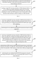
- FIG. 6 is a flowchart of a method of precoding indication for non-codebook based PUSCH transmission according to an embodiment of the present disclosure. As illustrated in FIG. 6 , the method is performed by a UE, and may include the following step.
- a single DCI carrying a plurality of SRI indication fields is received, in which, the single DCI indicates precoding information used by the UE during performing non-codebook based PUSCH STxMP under single DCI scheduling.
- Each SRI indication field among the plurality of SRI indication fields indicates one or more SRS resources carrying the precoding information in an associated SRS resource set, rendering that the UE, in a case of performing STxMP, performs non-codebook based PUSCH transmission in a corresponding beam direction using the precoding information indicated by each SRI indication field.
- Respective counts of SRS resources in the SRS resource set allocated for the PUSCH transmission in respective beam directions of the UE are not completely the same, and respective maximum counts of uplink transmission layers supported by the PUSCH transmission in respective beam directions are not completely the same.
- the SRI indication field is used to carry an index, and the index is used to indicate one or more SRS resources selected by the network device from the plurality of SRS resources configured for the UE.
- the network device in a non-codebook based uplink transmission mode, sends the single DCI carrying the plurality of SRI indication fields to the UE, to configure for the UE the SRS resources used for the PUSCH transmission in each beam direction.
- the respective maximum counts of uplink transmission layers supported by the PUSCH transmission in the respective beam directions of the UE and the respective counts of SRS resources in the SRS resource set allocated for the PUSCH transmission in the respective beam directions may be configured through signaling.
- the maximum counts of uplink transmission layers supported by the PUSCH transmission in different beam directions of the UE may be different, the counts of SRS resources in the SRS resource set allocated for the PUSCH transmission in different beam directions may also be different.
- an association between the SRI indication field and the SRS resource set may be predefined or indicated by an SRS resource set indication field in the single DCI.
- TCI beam indication information carried in the single DCI sent by the network device indicates three beams (corresponding to a first beam direction, a second beam direction, and a third beam direction respectively), and transmission configuration information carried in the single DCI includes three SRI indication fields (that is, a first SRI indication field, a second SRI indication field and a third SRI indication field, respectively).
- the network device and the UE may predefine that, the first SRI indication field instructs to select SRS resources from an SRS resource set allocated for PUSCH transmission in the first beam direction, that is, the first SRI indication field indicates the SRS resources used for the PUSCH transmission in the first beam direction, and the second SRI indication field instructs to select SRS resources from an SRS resource set allocated for PUSCH transmission in the second beam direction, and the third SRI indication field instructs to select SRS resources from an SRS resource set allocated for PUSCH transmission in the third beam direction.
- the network device may indicates through the SRS resource set indication field in the single DCI. For example, the SRS resource set indication field is newly added to the single DCI.
- the SRS resource set indication field indicates that the first SRI indication field instructs to select the SRS resources from the SRS resource set allocated for the PUSCH transmission in the first beam direction, and the second SRI indication field instructs to select the SRS resources from the SRS resource set allocated for the PUSCH transmission in the second beam direction, and the third SRI indication field instructs to select SRS resources from the SRS resource set allocated for the PUSCH transmission in the third beam direction.
- a correspondence between the beam direction and the PUSCH transmission is determined by any one of: an antenna panel, a transmission and reception point (TRP), transmission control information (TCI), a PUSCH transmission occasion (TO), or an SRS resource set.
- TRP transmission and reception point
- TCI transmission control information
- TO PUSCH transmission occasion
- SRS resource set any one of: an antenna panel, a transmission and reception point (TRP), transmission control information (TCI), a PUSCH transmission occasion (TO), or an SRS resource set.
- the PUSCH transmission may be associated with the antenna panel/TRP/PUSCH TO/SRS resource set.
- the UE performs the PUSCH transmission in two beam directions through two antenna panels.
- Antenna panel 1 sends beam 1 to a northwest direction
- antenna panel 2 sends beam 2 to a northeast direction.
- the beam 1 may correspond to a channel PUSCH1
- the beam 2 may correspond to a channel PUSCH2.
- the non-codebook based PUSCH transmission is performed based on the single DCI.
- the UE After receiving the single DCI, the UE performs the PUSCH transmission based on the single DCI.
- the single DCI carrying the plurality of SRI indication fields is sent to the UE, to indicate the precoding information used by the UE during performing the non-codebook based PUSCH STxMP under single DCI scheduling.
- the UE performs the non-codebook based PUSCH transmission in the corresponding beam direction using the precoding information carried by one or more SRS resources indicated by each SRI indication field.
- the respective counts of SRS resources in the SRS resource set allocated for the PUSCH transmission in the respective beam directions of the UE are not completely the same, and the respective maximum counts of uplink transmission layers supported by the PUSCH transmission in the respective beam directions are not completely the same. This may allow the UE to flexibly implement simultaneous uplink transmission for multiple TRPs through multiple antenna panels, which may further improve uplink system transmission throughput and transmission reliability.
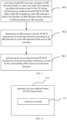
- FIG. 7 is a flowchart of a method of precoding indication for non-codebook based PUSCH transmission according to an embodiment of the present disclosure. As illustrated in FIG. 7 , the method is performed by a UE, and may include the following step.
- a single DCI carrying a plurality of SRI indication fields is received, in which, the single DCI indicates precoding information used by the UE during performing non-codebook based PUSCH STxMP under single DCI scheduling, each SRI indication field of the plurality of SRI indication fields indicates an SRI and a transmission rank indication (TRI) according to an SRI preconfiguration table.
- Respective counts of SRS resources in the SRS resource set allocated for the PUSCH transmission in respective beam directions of the UE are not completely the same, and respective maximum counts of uplink transmission layers supported by the PUSCH transmission in respective beam directions are not completely the same.
- the SRI preconfiguration table is determined according to a maximum count of uplink transmission layers supported by the PUSCH transmission in the corresponding beam direction and a count of SRS resources in an SRS resource set allocated for the PUSCH transmission in the corresponding beam direction, a count of bits occupied by each SRI indication field is determined based on a count of available SRI combinations in the SRI preconfiguration table.
- the network device may determine that the SRI preconfiguration table for the PUSCH transmission in the beam direction is a table corresponding to black bold texts in Table 1.
- the SRI indication field used to indicate the SRS resources for the PUSCH transmission in the beam direction may indicate the SRI and the TRI according to this table (implicitly indicated by the count of SRIs).
- the network device may determine that the SRI preconfiguration table for the PUSCH transmission in the beam direction is a table corresponding to black bold texts in Table 2.
- the SRI indication field used to indicate the SRS resources for the PUSCH transmission in the beam direction may indicate the SRI and the TRI according to this table.
- an SRS resource used for PUSCH transmission in each beam direction is determined according to an SRI and a TRI indicated by each SRI indication field of the plurality of SRI indication fields and an SRI preconfiguration table.
- the UE can determine a maximum count of uplink transmission layers supported by the PUSCH transmission in each beam direction and a count of SRS resources in an SRS resource set allocated for the PUSCH transmission in each beam direction, and may further determine the SRI preconfiguration table for the PUSCH transmission in each beam direction.
- the UE After receiving the single DCI, the UE determines the SRS resources for the PUSCH transmission in each beam direction based on the SRI and the TRI indicated in each SRI indication field included in the transmission configuration information carried in the single DCI, as well as the SRI preconfiguration table.
- the UE receives TCI beam indication information carried in the DCI sent by the network device indicates two beams, namely a first beam direction and a second beam direction, and transmission configuration information includes two SRI indication fields, namely a first SRI indication field and a second SRI indication field.
- the first SRI indication field carries index 6 and the second SRI indication field indicates index 1.
- the UE determines that the SRI preconfiguration table used for the PUSCH transmission in the first beam direction is the table corresponding to black bold texts in Table 1 above
- the codebook preconfiguration table used for the PUSCH transmission in the second beam direction is the table corresponding to black bold texts in Table 2 above.
- the non-codebook based PUSCH transmission is performed using the precoding information carried by the corresponding SRS resource in each beam direction.
- the UE After determining the SRS resource for the PUSCH transmission in each beam direction, the UE performs the non-codebook based PUSCH transmission using the precoding information carried by the determined SRS resource in each beam direction.
- an association between the SRI indication field and the SRS resource set may be predefined or indicated by an SRS resource set indication field in the single DCI.
- TCI beam indication information carried in the single DCI sent by the network device indicates three beams (corresponding to a first beam direction, a second beam direction, and a third beam direction respectively), and transmission configuration information carried in the single DCI includes three SRI indication fields (that is, a first SRI indication field, a second SRI indication field and a third SRI indication field, respectively).
- the network device and the UE may predefine that, the first SRI indication field instructs to select SRS resources from an SRS resource set allocated for PUSCH transmission in the first beam direction, that is, the first SRI indication field indicates the SRS resources used for the PUSCH transmission in the first beam direction, and the second SRI indication field instructs to select SRS resources from an SRS resource set allocated for PUSCH transmission in the second beam direction, and the third SRI indication field instructs to select SRS resources from an SRS resource set allocated for PUSCH transmission in the third beam direction.
- the network device may indicates through the SRS resource set indication field in the single DCI. For example, the SRS resource set indication field is newly added to the single DCI.
- the SRS resource set indication field indicates that the first SRI indication field instructs to select the SRS resources from the SRS resource set allocated for the PUSCH transmission in the first beam direction, and the second SRI indication field instructs to select the SRS resources from the SRS resource set allocated for the PUSCH transmission in the second beam direction, and the third SRI indication field instructs to select SRS resources from the SRS resource set allocated for the PUSCH transmission in the third beam direction.
- the single DCI carrying the plurality of SRI indication fields is sent to the UE, to indicate the precoding information used by the UE during performing the non-codebook based PUSCH STxMP under the single DCI scheduling.
- the respective counts of SRS resources in the SRS resource set allocated for the PUSCH transmission in the respective beam directions of the UE are not completely the same, and the respective maximum counts of uplink transmission layers supported by the PUSCH transmission in the respective beam directions are not completely the same, and each SRI indication field indicates both the SRI and the TRI. This may allow the UE to flexibly implement simultaneous uplink transmission for multiple TRPs through multiple antenna panels, which may further improve uplink system transmission throughput and transmission reliability.
- FIG. 8 is a flowchart of a method of precoding indication for non-codebook based PUSCH transmission according to an embodiment of the present disclosure. As illustrated in FIG. 8 , the method is performed by a network device, and may include the following step.
- a single DCI carrying a plurality of SRI indication fields is received, in which, the single DCI indicates precoding information used by the UE during performing non-codebook based PUSCH STxMP under single DCI scheduling, one SRI indication field among the plurality of SRI indication fields indicates an SRI and a TRI according to an SRI preconfiguration table, and each of other SRI indication fields among the plurality of SRI indication fields respectively indicate SRIs according to an SRI sub-table, in which, the SRI sub-table is determined from the SRI preconfiguration table according to the TRI.
- Respective counts of SRS resources in the SRS resource set allocated for the PUSCH transmission in respective beam directions of the UE are not completely the same, and respective maximum counts of uplink transmission layers supported by the PUSCH transmission in respective beam directions are not completely the same, and the same TRI is used for PUSCH transmission in each beam direction of the UE.
- a count of bits occupied by the one SRI indication field for indicating the SRI and the TRI is determined according to a count of available SRI combinations in the SRI preconfiguration table.
- a count of bits occupied by each SRI indication field in the other SRI indication fields for indicating the SRIs is determined according to a maximum value N max of a count of available SRI combinations corresponding to each available TRI in the corresponding SRI preconfiguration table.
- Each available TRI is determined a less one of a maximum count of uplink transmission layers supported by the PUSCH transmission in the corresponding beam direction and a count of SRS resources in an SRS resource set allocated for the PUSCH transmission in the corresponding beam direction
- the network device may determine that the SRI preconfiguration table for the PUSCH transmission in the beam direction is a table corresponding to black bold texts in Table 1.
- the SRI indication field used to indicate the SRS resources for the PUSCH transmission in the beam direction may indicate the SRI and the TRI according to this table (implicitly indicated by the count of SRIs).
- the network device may determine that the SRI preconfiguration table for the PUSCH transmission in the beam direction is a table corresponding to black bold texts in Table 2.
- L max L max
- N SRS N SRS
- the count of available SRI combinations is 3.
- an SRS resource used for the PUSCH transmission in the corresponding beam direction is determined according to an SRI and a TRI indicated by one SRI indication field among the plurality of SRI indication fields and an SRI preconfiguration table.
- an SRS resource used for the PUSCH transmission in each corresponding beam direction is determined according to SRIs respectively indicated by each SRI indication field of other SRI indication fields among the plurality of SRI indication fields and an SRI sub-table.
- the UE can determine a maximum count of uplink transmission layers supported by the PUSCH transmission in each beam direction and a count of SRS resources in an SRS resource set allocated for the PUSCH transmission in each beam direction, and may further determine the SRI preconfiguration table for the PUSCH transmission in each beam direction.
- the UE determines the SRS resource for the PUSCH transmission in each beam direction based on the SRI and TRI indicated in one SRI indication field carried in the single DCI, as well as the SRI preconfiguration table, and determines the SRS resource for the PUSCH transmission in the corresponding beam direction based on the SRIs carried in other SRI indication fields carried in the single DCI and the SRI sub-table.
- the UE determines the SRI sub-table from the corresponding SRI preconfiguration table based on the TRI indicated in one SRI indication field.
- the UE receives the TCI beam indication information carried in the DCI sent by the network device indicates two beams, namely a first beam direction and a second beam direction, and transmission configuration information includes two SRI indication fields, namely a first SRI indication field and a second SRI indication field.
- the first SRI indication field carries index 6 and the second SRI indication field indicates index 1.
- the UE determines that the SRI preconfiguration table used for the PUSCH transmission in the first beam direction is the table corresponding to black bold texts in Table 1 above
- the codebook preconfiguration table used for the PUSCH transmission in the second beam direction is the table corresponding to black bold texts in Table 2 above.
- the non-codebook based PUSCH transmission is performed using the precoding information carried by the corresponding SRS resource in each beam direction.
- the UE After determining the SRS resource for the PUSCH transmission in each beam direction, the UE performs the non-codebook based PUSCH transmission using the precoding information carried by the determined SRS resource in each beam direction.
- an association between the SRI indication field and the SRS resource set may be predefined or indicated by an SRS resource set indication field in the single DCI.
- TCI beam indication information carried in the single DCI sent by the network device indicates three beams (corresponding to a first beam direction, a second beam direction, and a third beam direction respectively), and transmission configuration information carried in the single DCI includes three SRI indication fields (that is, a first SRI indication field, a second SRI indication field and a third SRI indication field, respectively).
- the network device and the UE may predefine that, the first SRI indication field instructs to select SRS resources from an SRS resource set allocated for PUSCH transmission in the first beam direction, that is, the first SRI indication field indicates the SRS resources used for the PUSCH transmission in the first beam direction, and the second SRI indication field instructs to select SRS resources from an SRS resource set allocated for PUSCH transmission in the second beam direction, and the third SRI indication field instructs to select SRS resources from an SRS resource set allocated for PUSCH transmission in the third beam direction.
- the network device may indicates through the SRS resource set indication field in the single DCI. For example, the SRS resource set indication field is newly added to the single DCI.
- the SRS resource set indication field indicates that the first SRI indication field instructs to select the SRS resources from the SRS resource set allocated for the PUSCH transmission in the first beam direction, and the second SRI indication field instructs to select the SRS resources from the SRS resource set allocated for the PUSCH transmission in the second beam direction, and the third SRI indication field instructs to select SRS resources from the SRS resource set allocated for the PUSCH transmission in the third beam direction.
- the single DCI carrying the plurality of SRI indication fields is sent to the UE, to indicate the precoding information used by the UE during performing the non-codebook based PUSCH STxMP under single DCI scheduling.
- the respective counts of SRS resources in the SRS resource set allocated for the PUSCH transmission in the respective beam directions of the UE are not completely the same, and the respective maximum counts of uplink transmission layers supported by the PUSCH transmission in the respective beam directions are not completely the same.
- One SRI indication field among the plurality of SRI indication fields indicates the SRI and the TRI according to the SRI preconfiguration table, and other SRI indication fields indicate SRIs according to an SRI sub-table. Therefore, it may allow the UE to flexibly implement simultaneous uplink transmission for multiple TRPs through multiple antenna panels, which may further improve uplink system transmission throughput and transmission reliability.
- FIG. 9 is a flowchart of a method of precoding indication for non-codebook based PUSCH transmission according to an embodiment of the present disclosure. As illustrated in FIG. 9 , the method is performed by a network device, and may include the following step.
- a single DCI carrying a plurality of SRI indication fields is received, in which, the single DCI indicates precoding information used by the UE during performing non-codebook based PUSCH STxMP under single DCI scheduling, each SRI indication field of the plurality of SRI indication fields indicates an SRI according to an SRI sub-table.
- Respective counts of SRS resources in the SRS resource set allocated for the PUSCH transmission in respective beam directions of the UE are not completely the same, and respective maximum counts of uplink transmission layers supported by the PUSCH transmission in respective beam directions are not completely the same.
- the SRI sub-table is determined from a codebook preconfiguration table according to the TRI used for the PUSCH transmission in the corresponding beam direction, and the SRI preconfiguration table is determined based on a maximum count of uplink transmission layers supported by the PUSCH transmission in the corresponding beam direction and a count of SRS resources in an SRS resource set allocated for the PUSCH transmission in the corresponding beam direction, and a count of bits occupied by each SRI indication field is determined according to a maximum value N max of a count of available SRI combinations corresponding to each available TRI in the corresponding SRI preconfiguration table.
- Each available TRI is determined according to a less one of the maximum count of uplink transmission layers supported by the PUSCH transmission in the corresponding beam direction and the count of SRS
- the network device may determine that the SRI preconfiguration table for the PUSCH transmission in the beam direction is a table corresponding to black bold texts in Table 1.
- the network device obtains the value of the TRI used for the PUSCH transmission in the beam direction, the network device may determine that the corresponding SRI sub-table is a subset with the value of TRI being the obtained value in the table.
- a count of codepoints in the SRI sub-table is 2 ⁇ M2, wherein K2 codepoints respectively represent K2 SRI values corresponding to the specific TRI in the corresponding SRI preconfiguration table, and the remaining (2 ⁇ M2-K2) codepoints are reserved values, where M2 is log 2 (N2 max ) , ⁇ ⁇ denotes rounding up.
- an SRS resource used for PUSCH transmission in each beam direction is determined according to an SRI indicated by each SRI indication field and an SRI sub-table.
- the UE can determine a maximum count of uplink transmission layers supported by the PUSCH transmission in each beam direction and a count of SRS resources in an SRS resource set allocated for the PUSCH transmission in each beam direction, and may further determine the SRI preconfiguration table for the PUSCH transmission in each beam direction. In addition, the UE may determine the SRI sub-table used for the PUSCH transmission in each beam direction from the SRI preconfiguration table based on the TRI used for the PUSCH transmission in each beam direction. After receiving the single DCI, the UE determines the SRS resources for the PUSCH transmission in each beam direction based on the SRI indicated in each SRI indication field included in the transmission configuration information carried in the single DCI, as well as the SRI sub-table.
- the UE receives TCI beam indication information carried in the DCI sent by the network device indicates two beams, namely a first beam direction and a second beam direction, and transmission configuration information includes two SRI indication fields, namely a first SRI indication field and a second SRI indication field.
- the first SRI indication field carries index 2 and the second SRI indication field indicates index 5.
- the UE determines that the SRI preconfiguration table used for the PUSCH transmission in the first beam direction is the table corresponding to black bold texts in Table 1 above
- the codebook preconfiguration table used for the PUSCH transmission in the second beam direction is the table corresponding to black bold texts in Table 2 above.
- the non-codebook based PUSCH transmission is performed using the precoding information carried by the corresponding SRS resource in each beam direction.
- the UE After determining the SRS resource for the PUSCH transmission in each beam direction, the UE performs the non-codebook based PUSCH transmission using the precoding information carried by the determined SRS resource in each beam direction.
- an association between the SRI indication field and the SRS resource set may be predefined or indicated by an SRS resource set indication field in the single DCI.
- TCI beam indication information carried in the single DCI sent by the network device indicates three beams (corresponding to a first beam direction, a second beam direction, and a third beam direction respectively), and transmission configuration information carried in the single DCI includes three SRI indication fields (that is, a first SRI indication field, a second SRI indication field and a third SRI indication field, respectively).
- the network device and the UE may predefine that, the first SRI indication field instructs to select SRS resources from an SRS resource set allocated for PUSCH transmission in the first beam direction, that is, the first SRI indication field indicates the SRS resources used for the PUSCH transmission in the first beam direction, and the second SRI indication field instructs to select SRS resources from an SRS resource set allocated for PUSCH transmission in the second beam direction, and the third SRI indication field instructs to select SRS resources from an SRS resource set allocated for PUSCH transmission in the third beam direction.
- the network device may indicates through the SRS resource set indication field in the single DCI. For example, the SRS resource set indication field is newly added to the single DCI.
- the SRS resource set indication field indicates that the first SRI indication field instructs to select the SRS resources from the SRS resource set allocated for the PUSCH transmission in the first beam direction, and the second SRI indication field instructs to select the SRS resources from the SRS resource set allocated for the PUSCH transmission in the second beam direction, and the third SRI indication field instructs to select SRS resources from the SRS resource set allocated for the PUSCH transmission in the third beam direction.
- the single DCI carrying the plurality of SRI indication fields is sent to the UE, to indicate the precoding information used by the UE during performing the non-codebook based PUSCH STxMP under single DCI scheduling.
- the respective counts of SRS resources in the SRS resource set allocated for the PUSCH transmission in the respective beam directions of the UE are not completely the same, and the respective maximum counts of uplink transmission layers supported by the PUSCH transmission in the respective beam directions are not completely the same.
- Each SRI indication field indicates the SRI only. Therefore, it may allow the UE to flexibly implement simultaneous uplink transmission for multiple TRPs through multiple antenna panels, which may further improve uplink system transmission throughput and transmission reliability.
- the methods according to the embodiments of the disclosure are described from the perspectives of the user equipment and the network device, respectively.
- the user equipment and the network device may include a hardware structure, a software module, and realize each of the above functions in the form of hardware structure, software module, or a combination of hardware structure and software module.
- a certain function of the above functions may be performed in the form of hardware structure, software module, or a combination of hardware structure and software module.
- the present disclosure also provides an apparatus of precoding indication for non-codebook based PUSCH transmission.
- the apparatus of precoding indication for non-codebook based PUSCH transmission corresponds to the method of precoding indication for non-codebook based PUSCH transmission provided by the above-mentioned embodiments. Therefore, the implementation of the method of precoding indication for non-codebook based PUSCH transmission is also applicable to the apparatus of precoding indication for non-codebook based PUSCH transmission provided in this embodiment and will not be described in detail in this embodiment.
- FIG. 10 is a block diagram of an apparatus 1000 of precoding indication for non-codebook based PUSCH transmission according to an embodiment of the disclosure.
- the apparatus 1000 may be applied to the network device.
- the apparatus 1000 may include a transceiver module 1001.
- the transceiver module 1001 is configured to, send a single downlink control information (DCI) carrying a plurality of sounding reference signal (SRS) resource indicator (SRI) indication fields to a user equipment (UE), to indicate precoding information used by the UE during performing non-codebook based PUSCH simultaneous transmission from multiple panels (STxMP) under single DCI scheduling; in which, each SRI indication field indicates one or more SRS resources carrying the precoding information in an associated SRS resource set, rendering that the UE, in a case of performing STxMP, performs non-codebook based PUSCH transmission in a corresponding beam direction using the precoding information indicated by each SRI indication field.
- DCI downlink control information
- SRS sounding reference signal
- SRI resource indicator
- the single DCI carrying the plurality of SRS resource indicator (SRI) indication fields is sent to the UE, to indicate the precoding information used by the UE during performing the non-codebook based PUSCH STxMP under single DCI scheduling.
- SRI indication field among the plurality of SRI indication fields indicates one or more SRS resources carrying the precoding information in the associated SRS resource set, rendering that the UE, in a case of performing STxMP, performs the non-codebook based PUSCH transmission in the corresponding beam direction using the precoding information carried by one or more SRS resources indicated by each SRI indication field.
- Respective counts of SRS resources in the SRS resource set allocated for the PUSCH transmission in respective beam directions of the UE are not completely the same, and respective maximum counts of uplink transmission layers supported by the PUSCH transmission in respective beam directions are not completely the same. This may allow the UE to flexibly implement simultaneous uplink transmission for multiple TRPs through multiple antenna panels, which may further improve uplink system transmission throughput and transmission reliability.
- each SRI indication field indicates an SRI and a transmission rank indication (TRI) according to an SRI preconfiguration table
- the SRI preconfiguration table is determined according to a maximum count of uplink transmission layers supported by the PUSCH transmission in the corresponding beam direction and a count of SRS resources in an SRS resource set allocated for the PUSCH transmission in the corresponding beam direction
- a count of bits occupied by each SRI indication field is determined based on a count of available SRI combinations in the SRI preconfiguration table.
- one SRI indication field among the plurality of SRI indication fields indicates an SRI and a TRI according to an SRI preconfiguration table, and a count of bits occupied by the one SRI indication field is determined according to a count of available SRI combinations in the SRI preconfiguration table;
- the transceiver module 1001 is further configured to:
- a count of codepoints in the SRI sub-table is 2 ⁇ M, in which, K codepoints respectively represent K SRI values corresponding to the specific TRI in the corresponding SRI preconfiguration table, and the remaining (2 ⁇ M-K) codepoints are reserved values, where M is log 2 (N max ) , ⁇ ⁇ denotes rounding up.
- the rank indication information is obtained according to any one of:
- an association between the SRI indication field and the SRS resource set is predefined or indicated by an SRS resource set indication field in the single DCI.
- a correspondence between the beam direction and the PUSCH transmission is determined by any one of: an antenna panel, a transmission and reception point (TRP), transmission control information (TCI), a PUSCH transmission occasion (TO), or an SRS resource set.
- TRP transmission and reception point
- TCI transmission control information
- TO PUSCH transmission occasion
- SRS resource set any one of: an antenna panel, a transmission and reception point (TRP), transmission control information (TCI), a PUSCH transmission occasion (TO), or an SRS resource set.
- FIG. 11 is a block diagram of an apparatus 1100 of precoding indication for non-codebook based PUSCH transmission according to an embodiment of the disclosure.
- the apparatus 1100 may be applied to the UE.
- the apparatus 1100 may include a transceiver module 1101 and a processing module 1102.
- the transceiver module 1101 is configured to receive a single downlink control information (DCI) carrying a plurality of sounding reference signal (SRS) resource indicator (SRI) indication fields, in which, the single DCI indicates precoding information used by the UE during performing non-codebook based PUSCH simultaneous transmission from multiple panels (STxMP) under single DCI scheduling, wherein each SRI indication field of the plurality of SRI indication fields indicates one or more SRS resources carrying the precoding information in an associated SRS resource set, rendering that the UE, in a case of performing STxMP, performs non-codebook based PUSCH transmission in a corresponding beam direction using the precoding information carried by the one or more SRS resources indicated by each SRI indication field; and
- DCI downlink control information
- SRS sounding reference signal
- SRI resource indicator
- the processing module 1102 is configured to perform the non-codebook based PUSCH transmission based on the single DCI.
- the single DCI carrying the plurality of SRS resource indicator (SRI) indication fields is sent to the UE, to indicate the precoding information used by the UE during performing the non-codebook based PUSCH STxMP under single DCI scheduling.
- SRI indication field among the plurality of SRI indication fields indicates one or more SRS resources carrying the precoding information in the associated SRS resource set, rendering that the UE, in a case of performing STxMP, performs the non-codebook based PUSCH transmission in the corresponding beam direction using the precoding information carried by one or more SRS resources indicated by each SRI indication field.
- Resp ective counts of SRS resources in the SRS resource set allocated for the PUSCH transmission in respective beam directions of the UE are not completely the same, and respective maximum counts of uplink transmission layers supported by the PUSCH transmission in respective beam directions are not completely the same. This may allow the UE to flexibly implement simultaneous uplink transmission for multiple TRPs through multiple antenna panels, which may further improve uplink system transmission throughput and transmission reliability.
- the processing module 1102 is configured to determine an SRS resource used for PUSCH transmission in each beam direction according to an SRI and a transmission rank indication (TRI) indicated by each SRI indication field and an SRI preconfiguration table, in which, the SRI preconfiguration table is determined according to a maximum count of uplink transmission layers supported by the PUSCH transmission in the corresponding beam direction and a count of SRS resources in an SRS resource set allocated for the PUSCH transmission in the corresponding beam direction, a count of bits occupied by each SRI indication field is determined based on a count of available SRI combinations in the SRI preconfiguration table; and the transceiver module 1101 is configured to perform the non-codebook based PUSCH transmission using the precoding information carried by the corresponding SRS resource in each beam direction.
- TRI transmission rank indication
- the processing module 1102 is configured to determine an SRS resource used for the PUSCH transmission in the corresponding beam direction according to an SRI and a TRI indicated by one SRI indication field among the plurality of SRI indication fields and an SRI preconfiguration table, in which, a count of bits occupied by the one SRI indication field is determined according to a count of available SRI combinations in the SRI preconfiguration table;
- the processing module 1102 is configured to determine an SRS resource used for PUSCH transmission in each beam direction according to an SRI indicated by each SRI indication field and an SRI sub-table, in which, the SRI sub-table is determined from an SRI pre-configuration table according to a TRI used for the PUSCH transmission in the corresponding beam direction, and the SRI preconfiguration table is determined based on a maximum count of uplink transmission layers supported by the PUSCH transmission in the corresponding beam direction and a count of SRS resources in an SRS resource set allocated for the PUSCH transmission in the corresponding beam direction, and a count of bits occupied by each SRI indication field is determined according to a maximum value N max of a count of available SRI combinations corresponding to each available TRI in the corresponding SRI preconfiguration table, where each available TRI is an integer greater than or equal to 1 and less than or equal to a first value, the first value is a less one of the maximum count of uplink transmission layers supported by the PUSCH transmission in the corresponding
- a count of codepoints in the SRI sub-table is 2 ⁇ M, in which, K codepoints respectively represent K SRI values corresponding to the specific TRI in the corresponding SRI preconfiguration table, and the remaining (2 ⁇ M-K) codepoints are reserved values, where M is ⁇ log 2 (N max ) ⁇ , ⁇ ⁇ denotes rounding up.
- an association between the SRI indication field and the SRS resource set is predefined or indicated by an SRS resource set indication field in the single DCI.
- a correspondence between the beam direction and the PUSCH transmission is determined by any one of: an antenna panel, a transmission and reception point (TRP), transmission control information (TCI), a PUSCH transmission occasion (TO), or an SRS resource set.
- TRP transmission and reception point
- TCI transmission control information
- TO PUSCH transmission occasion
- SRS resource set any one of: an antenna panel, a transmission and reception point (TRP), transmission control information (TCI), a PUSCH transmission occasion (TO), or an SRS resource set.
- FIG. 12 is a schematic structural diagram of a communication device 1200 provided by an embodiment of the present application.
- the communication device 1200 may be a network device, a user equipment, a chip, a chip system, or a processor that supports the network device to implement the above method, or a chip, a chip system, or a processor that supports the user equipment to implement the above method.
- the device can be used to implement the method described in the above method embodiment. For details, please refer to the description in the above method embodiment.
- the communication device 1200 may include one or more processors 1201.
- the processor 1201 may be a general purpose processor or a dedicated processor, such as, a baseband processor or a central processor.
- the baseband processor is used for processing communication protocols and communication data.
- the central processor is used for controlling the communication apparatus (e.g., base station, baseband chip, terminal device, terminal device chip, DU, or CU), executing computer programs, and processing data of the computer programs.
- the communication apparatus 1200 may include one or more memories 1202 on which computer programs 1204 may be stored.
- the processor 1201 executes the computer programs 1204 to cause the communication apparatus 1200 to perform the methods described in the above method embodiments.
- data may also be stored in the memory 1202.
- the communication apparatus 1200 and the memory 1202 may be set separately or integrated together.
- the communication apparatus 1200 may also include a transceiver 1205 and an antenna 1206.
- the transceiver 1205 may be referred to as transceiver unit, transceiver machine, or transceiver circuit, for realizing the transceiver function.
- the transceiver 1205 may include a receiver and a transmitter.
- the receiver may be referred to as receiver machine or receiving circuit, for realizing the receiving function.
- the transmitter may be referred to as transmitter machine or transmitting circuit, for realizing the transmitting function.
- the communication apparatus 1200 may also include one or more interface circuits 1207.
- the interface circuits 1207 are used to receive code instructions and transmit them to the processor 1201.
- the processor 1201 runs the code instructions to cause the communication apparatus 1200 to perform the method described in the method embodiments.
- the processor 1201 may include a transceiver for implementing the receiving and transmitting functions.
- the transceiver may be, for example, a transceiver circuit, an interface, or an interface circuit.
- the transceiver circuit, interface, or interface circuit for implementing the receiving and transmitting functions may be separated or may be integrated together.
- the transceiver circuit, interface, or interface circuit described above may be used for code/data reading and writing, or may be used for signal transmission or delivery.
- the processor 1201 may store a computer program 1203, and the computer program 1203 runs on the processor 1201, causing the communication device 1200 to perform the method described in the above method embodiment.
- the computer program 1203 may be solidified in the processor 1201, in which case the processor 1201 may be implemented by hardware.
- the communication device 1200 may include circuits.
- the circuits may implement the sending, receiving or communicating function in the preceding method embodiments.
- the processor and transceiver described in this disclosure may be implemented on integrated circuits (ICs), analog ICs, radio frequency integrated circuits (RFICs), mixed signal ICs, application specific integrated circuits (ASICs), printed circuit boards (PCBs), and electronic devices.
- ICs integrated circuits
- RFICs radio frequency integrated circuits
- ASICs application specific integrated circuits
- PCBs printed circuit boards
- the processor and transceiver may also be produced using various IC process technologies, such as complementary metal oxide semiconductor (CMOS), nMetal-oxide-semiconductor (NMOS), positive channel metal oxide semiconductor (PMOS), bipolar junction transistor (BJT), bipolar CMOS (BiCMOS), silicon-germanium (SiGe), gallium arsenide (GaAs) and so on.
- CMOS complementary metal oxide semiconductor
- NMOS nMetal-oxide-semiconductor
- PMOS positive channel metal oxide semiconductor
- BJT bipolar junction transistor
- BiCMOS bipolar CMOS
- SiGe silicon-germanium
- GaAs gallium arsenide
- the communication device in the above description of embodiments may be a network side device or a terminal device, but the scope of the communication device described in the disclosure is not limited thereto, and the structure of the communication device may not be limited by FIG. 12 .
- the communication device may be a stand-alone device or may be part of a larger device.
- the described communication device may be:
- the communication apparatus may be a chip or a chip system may be referred to the schematic structural diagram of the chip shown in FIG. 13 .
- the chip includes a processor 1301 and an interface 1302. There may be one or more processors 1301, and there may be multiple interfaces 1302.
- the chip further includes a memory 1303 used for storing necessary computer programs and data.
- the disclosure also provides a readable storage medium having instructions stored thereon. When the instructions are executed by a computer, the function of any of the method embodiments described above is implemented.
- the disclosure also provides a computer program product.
- the computer program product is executed by a computer, the function of any of the method embodiments described above is implemented.
- the above embodiments may be implemented in whole or in part by software, hardware, firmware, or any combination thereof.
- software When implemented using software, it may be implemented, in whole or in part, in the form of a computer program product.
- the computer program product includes one or more computer programs. When loading and executing the computer programs on the computer, all or part of processes or functions described in the embodiments of the disclosure are implemented.
- the computer may be a general-purpose computer, a dedicated computer, a computer network, or other programmable devices.
- the computer program may be stored in a computer-readable storage medium or transmitted from one computer-readable storage medium to another computer-readable storage medium.
- the computer program may be transmitted from one web site, computer, server, or data center to another web site, computer, server, or data center, in a wired manner (e.g., by using coaxial cables, fiber optics, or digital subscriber lines (DSLs) or wirelessly (e.g., by using infrared wave, wireless wave, or microwave).
- the computer-readable storage medium may be any usable medium to which the computer has access or a data storage device such as a server and a data center integrated by one or more usable mediums.
- the usable medium may be a magnetic medium (e.g., floppy disk, hard disk, and tape), an optical medium (e.g., a high-density digital video disc (DVD)), or a semiconductor medium (e.g., a solid state disk (SSD)).
- a magnetic medium e.g., floppy disk, hard disk, and tape
- an optical medium e.g., a high-density digital video disc (DVD)
- DVD high-density digital video disc
- SSD solid state disk
- the term “at least one” in the disclosure may also be described as one or more, and the term “multiple” may be two, three, four, or more, which is not limited in the disclosure.
- “first”, “second”, and “third”, and “A”, “B”, “C” and “D” are used to distinguish different technical features of the type, the technical features described using the “first”, “second”, and “third”, and “A”, “B”, “C” and “D” do not indicate any order of precedence or magnitude.
- machine-readable medium and “computer-readable medium” refer to as any computer program product, device, and/or apparatus (for example, a magnetic disk, an optical disk, a memory, a programmable logic device (PLD)) for providing machine instructions and/or data to a programmable processor, including a machine-readable medium that receives machine instructions as machine-readable signals.
- machine-readable signal refers to as any signal for providing the machine instructions and/or data to the programmable processor.
- the systems and techniques described herein may be implemented in a computing system including a back-end component (e.g., as a data server), or a computing system including a middleware component (e.g., an application server), or a computing system including a front-end component (e.g., a user computer having a graphical user interface or web browser through which the user can interact with implementations of the systems and technologies described herein), or a computing system including any combination of such backend component, middleware component, or front-end component.
- the components of the system may be interconnected by any form or medium of digital data communication (e. g., a communications network). Examples of communication networks may include: a local area network (LAN), a wide area network (WAN), and the Internet.
- the computer system may include a client and a server.
- the client and the server are generally remote from each other and typically interact over the communications network.
- the relationship of client and server is created by a computer program running on corresponding computers and having a client-server relationship with each other.
Landscapes
- Engineering & Computer Science (AREA)
- Signal Processing (AREA)
- Computer Networks & Wireless Communication (AREA)
- Mobile Radio Communication Systems (AREA)
Applications Claiming Priority (1)
| Application Number | Priority Date | Filing Date | Title |
|---|---|---|---|
| PCT/CN2022/111585 WO2024031488A1 (zh) | 2022-08-10 | 2022-08-10 | 基于非码本的pusch传输的预编码指示方法 |
Publications (2)
| Publication Number | Publication Date |
|---|---|
| EP4572201A1 true EP4572201A1 (de) | 2025-06-18 |
| EP4572201A4 EP4572201A4 (de) | 2025-08-06 |
Family
ID=89850239
Family Applications (1)
| Application Number | Title | Priority Date | Filing Date |
|---|---|---|---|
| EP22954460.6A Pending EP4572201A4 (de) | 2022-08-10 | 2022-08-10 | Vorcodierungsanzeigeverfahren für nicht-codebuch-basierte pusch-übertragung |
Country Status (3)
| Country | Link |
|---|---|
| EP (1) | EP4572201A4 (de) |
| CN (1) | CN117882327A (de) |
| WO (1) | WO2024031488A1 (de) |
Family Cites Families (6)
| Publication number | Priority date | Publication date | Assignee | Title |
|---|---|---|---|---|
| CN113271188B (zh) * | 2020-02-14 | 2022-12-16 | 大唐移动通信设备有限公司 | 一种数据传输方法、终端和基站 |
| US12028859B2 (en) * | 2020-05-13 | 2024-07-02 | Intel Corporation | UE configured for PUSCH repetition based on TPMI index and SRI |
| WO2021237666A1 (en) * | 2020-05-29 | 2021-12-02 | Qualcomm Incorporated | Precoder indication for non-codebook-based uplink transmissions |
| CN113824481B (zh) * | 2020-06-19 | 2023-03-28 | 华为技术有限公司 | 上行传输方法、装置、芯片系统及存储介质 |
| EP4231566A4 (de) * | 2020-10-19 | 2024-07-24 | Beijing Xiaomi Mobile Software Co., Ltd. | Pusch-anzeigeverfahren und -vorrichtung sowie pusch-sendeverfahren und -vorrichtung |
| US20240073890A1 (en) * | 2021-01-08 | 2024-02-29 | Ntt Docomo, Inc. | Terminal, radio communication method, and base station |
-
2022
- 2022-08-10 EP EP22954460.6A patent/EP4572201A4/de active Pending
- 2022-08-10 WO PCT/CN2022/111585 patent/WO2024031488A1/zh not_active Ceased
- 2022-08-10 CN CN202280003089.XA patent/CN117882327A/zh active Pending
Also Published As
| Publication number | Publication date |
|---|---|
| EP4572201A4 (de) | 2025-08-06 |
| WO2024031488A1 (zh) | 2024-02-15 |
| CN117882327A (zh) | 2024-04-12 |
Similar Documents
| Publication | Publication Date | Title |
|---|---|---|
| US20250274242A1 (en) | Method and device for determining transmission configuration indication state | |
| US20250260543A1 (en) | Method and apparatus for determining transmission configuration indication state | |
| US20250365183A1 (en) | Method and apparatus for indicating transmission configuration indication state | |
| US20240188054A1 (en) | Method and device for time-domain resource allocation | |
| EP4550905A1 (de) | Verfahren zur bestimmung der nutzungszeit eines zustands einer übertragungskonfigurationsanzeige (tci) und vorrichtung dafür | |
| US20250274915A1 (en) | Methods and apparatuses for data transmission | |
| US20240380531A1 (en) | Frequency hopping method and apparatus | |
| US20250358083A1 (en) | Indication methods for transmission configuration indication state, and apparatuses | |
| EP4412344A1 (de) | Übertragungskonfigurationsverfahren und -vorrichtung für mehrere sende- und empfangspunkte (trps) | |
| EP4325756A1 (de) | Verfahren und vorrichtung zum multiplexing von uplink-steuerungsinformationen | |
| EP4712625A1 (de) | Verfahren zur bestimmung einer berechtigungsfreien uplink-ressource, verfahren zur konfiguration einer berechtigungsfreien uplink-ressource und vorrichtung | |
| EP4586564A1 (de) | Informationsbestimmungsverfahren/-vorrichtung/-vorrichtung und speichermedium | |
| EP4319001A1 (de) | Verfahren und vorrichtung zur datenempfangsverarbeitung | |
| EP4572201A1 (de) | Vorcodierungsanzeigeverfahren für nicht-codebuch-basierte pusch-übertragung | |
| US20250373290A1 (en) | Method and apparatus for determining uplink mimo transmission codeword | |
| EP4560955A1 (de) | Verbessertes übertragungskonfigurationsverfahren mit mehreren tafeln und vorrichtung dafür | |
| EP4444009A1 (de) | Verfahren und vorrichtung zur bestimmung des zeitschlitzversatzes zwischen hybriden automatischen wiederholungsanfragen sowie verfahren und vorrichtung zur anzeige des zeitschlitzversatzes zwischen hybriden automatischen wiederholungsanfragen | |
| EP4693986A1 (de) | Kommunikationsverarbeitungsverfahren und -vorrichtung | |
| WO2023065325A1 (zh) | 基于轨道角动量的共享信道传输及装置 | |
| EP4572457A1 (de) | Vorcodierungsanzeigeverfahren und -vorrichtung | |
| CN113439421B (zh) | 一种联合信道估计方法及其装置 | |
| EP4564751A1 (de) | Verfahren und vorrichtung zur kanalschätzung | |
| EP4604434A1 (de) | Verfahren und vorrichtung zur übertragung eines gemeinsam genutzten physikalischen downlink-kanals (pdsch) | |
| RU2847786C2 (ru) | Способ определения состояния индикации конфигурации передачи и устройство | |
| EP4723782A1 (de) | Kommunikationsverfahren und vorrichtung dafür |
Legal Events
| Date | Code | Title | Description |
|---|---|---|---|
| STAA | Information on the status of an ep patent application or granted ep patent |
Free format text: STATUS: THE INTERNATIONAL PUBLICATION HAS BEEN MADE |
|
| PUAI | Public reference made under article 153(3) epc to a published international application that has entered the european phase |
Free format text: ORIGINAL CODE: 0009012 |
|
| STAA | Information on the status of an ep patent application or granted ep patent |
Free format text: STATUS: REQUEST FOR EXAMINATION WAS MADE |
|
| 17P | Request for examination filed |
Effective date: 20250307 |
|
| AK | Designated contracting states |
Kind code of ref document: A1 Designated state(s): AL AT BE BG CH CY CZ DE DK EE ES FI FR GB GR HR HU IE IS IT LI LT LU LV MC MK MT NL NO PL PT RO RS SE SI SK SM TR |
|
| A4 | Supplementary search report drawn up and despatched |
Effective date: 20250709 |
|
| RIC1 | Information provided on ipc code assigned before grant |
Ipc: H04L 5/00 20060101AFI20250703BHEP Ipc: H04B 7/06 20060101ALI20250703BHEP |
|
| DAV | Request for validation of the european patent (deleted) | ||
| DAX | Request for extension of the european patent (deleted) |