EP4572070A1 - Leistungssteuerungssystem - Google Patents
Leistungssteuerungssystem Download PDFInfo
- Publication number
- EP4572070A1 EP4572070A1 EP23852180.1A EP23852180A EP4572070A1 EP 4572070 A1 EP4572070 A1 EP 4572070A1 EP 23852180 A EP23852180 A EP 23852180A EP 4572070 A1 EP4572070 A1 EP 4572070A1
- Authority
- EP
- European Patent Office
- Prior art keywords
- electric power
- bus line
- voltage
- converter
- power generation
- Prior art date
- Legal status (The legal status is an assumption and is not a legal conclusion. Google has not performed a legal analysis and makes no representation as to the accuracy of the status listed.)
- Pending
Links
Images


Classifications
-
- H—ELECTRICITY
- H02—GENERATION; CONVERSION OR DISTRIBUTION OF ELECTRIC POWER
- H02J—ELECTRIC POWER NETWORKS; CIRCUIT ARRANGEMENTS OR SYSTEMS FOR SUPPLYING OR DISTRIBUTING ELECTRIC POWER; SYSTEMS FOR STORING ELECTRIC ENERGY
- H02J3/00—Circuit arrangements for AC mains or AC distribution networks
- H02J3/38—Arrangements for feeding a single network from two or more generators or sources in parallel; Arrangements for feeding already energised networks from additional generators or sources in parallel
- H02J3/381—Dispersed generators
-
- H—ELECTRICITY
- H02—GENERATION; CONVERSION OR DISTRIBUTION OF ELECTRIC POWER
- H02J—ELECTRIC POWER NETWORKS; CIRCUIT ARRANGEMENTS OR SYSTEMS FOR SUPPLYING OR DISTRIBUTING ELECTRIC POWER; SYSTEMS FOR STORING ELECTRIC ENERGY
- H02J1/00—Circuit arrangements for DC mains or DC distribution networks
- H02J1/08—Three-wire DC power distribution systems; Systems having more than three wires
- H02J1/082—DC supplies with two or more different DC voltage levels
-
- H—ELECTRICITY
- H02—GENERATION; CONVERSION OR DISTRIBUTION OF ELECTRIC POWER
- H02J—ELECTRIC POWER NETWORKS; CIRCUIT ARRANGEMENTS OR SYSTEMS FOR SUPPLYING OR DISTRIBUTING ELECTRIC POWER; SYSTEMS FOR STORING ELECTRIC ENERGY
- H02J15/00—Systems for storing electric energy specially adapted for power networks
- H02J15/50—Systems for storing electric energy specially adapted for power networks using stored hydrogen
-
- H—ELECTRICITY
- H02—GENERATION; CONVERSION OR DISTRIBUTION OF ELECTRIC POWER
- H02J—ELECTRIC POWER NETWORKS; CIRCUIT ARRANGEMENTS OR SYSTEMS FOR SUPPLYING OR DISTRIBUTING ELECTRIC POWER; SYSTEMS FOR STORING ELECTRIC ENERGY
- H02J3/00—Circuit arrangements for AC mains or AC distribution networks
- H02J3/28—Arrangements for balancing of the load in networks by storage of energy
- H02J3/32—Arrangements for balancing of the load in networks by storage of energy using batteries or super capacitors with converting means
-
- H—ELECTRICITY
- H02—GENERATION; CONVERSION OR DISTRIBUTION OF ELECTRIC POWER
- H02J—ELECTRIC POWER NETWORKS; CIRCUIT ARRANGEMENTS OR SYSTEMS FOR SUPPLYING OR DISTRIBUTING ELECTRIC POWER; SYSTEMS FOR STORING ELECTRIC ENERGY
- H02J2101/00—Supply or distribution of decentralised, dispersed or local electric power generation
- H02J2101/20—Dispersed power generation using renewable energy sources
- H02J2101/22—Solar energy
- H02J2101/24—Photovoltaics
-
- H—ELECTRICITY
- H02—GENERATION; CONVERSION OR DISTRIBUTION OF ELECTRIC POWER
- H02J—ELECTRIC POWER NETWORKS; CIRCUIT ARRANGEMENTS OR SYSTEMS FOR SUPPLYING OR DISTRIBUTING ELECTRIC POWER; SYSTEMS FOR STORING ELECTRIC ENERGY
- H02J2101/00—Supply or distribution of decentralised, dispersed or local electric power generation
- H02J2101/20—Dispersed power generation using renewable energy sources
- H02J2101/30—Fuel cells
-
- H—ELECTRICITY
- H02—GENERATION; CONVERSION OR DISTRIBUTION OF ELECTRIC POWER
- H02J—ELECTRIC POWER NETWORKS; CIRCUIT ARRANGEMENTS OR SYSTEMS FOR SUPPLYING OR DISTRIBUTING ELECTRIC POWER; SYSTEMS FOR STORING ELECTRIC ENERGY
- H02J7/00—Circuit arrangements for charging or discharging batteries or for supplying loads from batteries
- H02J7/34—Parallel operation in networks using both storage and other DC sources, e.g. providing buffering
Definitions
- the present disclosure relates to a power (electric power) control system.
- Patent Literature 1 discloses a Direct Current (DC) bus control system using the fuel cell and the water electrolysis device.
- Patent Literature 1 International Patent Publication No. WO2019/103059
- each device is connected to one DC bus line via a DC/DC converter. Furthermore, in the case of a fuel cell and a water electrolysis device, a voltage specification value is lower than that of a power supply device, so that the DC bus line and each device need to be connected via two DC/DC converters. Therefore, in the case where the water electrolysis device and the fuel cell are electrically connected, a large power loss occurs.
- An object of the present invention is to provide an electric power control system capable of stabilizing power while suppressing power loss.
- a power control system including an electric power generation mechanism using renewable energy, a first DC(Direct Current) bus line connected to the electric power generation mechanism and corresponding to a first voltage, a DC/DC converter connected to the first DC bus line and capable of converting the first voltage into a second voltage lower than the first voltage, a second DC bus line connected to the DC/DC converter and corresponding to the second voltage, a power generation apparatus electrically connected to the second DC bus line, and a power generation fuel generation apparatus electrically connected to the second DC bus line and connected to the power generation apparatus, which is configured to generate fuel for use in power generation in the power generation apparatus.
- a first DC(Direct Current) bus line connected to the electric power generation mechanism and corresponding to a first voltage
- a DC/DC converter connected to the first DC bus line and capable of converting the first voltage into a second voltage lower than the first voltage
- a second DC bus line connected to the DC/DC converter and corresponding to the second voltage
- a power generation apparatus electrically connected to the second DC bus line
- the electric power generation mechanism may be a solar cell.
- the electric power control system may further include an electric power storage mechanism connected to the second DC bus line and storing electric power generated by the electric power generation mechanism.
- the power generation apparatus may be a fuel cell, and the power generation fuel generation apparatus may be a water electrolysis device.
- the electric power control system may further include a control device configured to control driving and termination of the power generation apparatus and the power generation fuel generation apparatus depending on a voltage value of a DC current in the first DC bus line.
- the electric power control system may include a first DC/AC converter connected to the first DC bus line; a second DC/AC converter connected to the second DC bus line; and a load connected to the first DC/AC converter and the second DC/AC converter, and when the first DC bus line satisfies a predetermined condition, the control device may supply power to the load via the second DC/AC converter.
- an electric power control system capable of stabilizing power while suppressing power loss.
- voltage can be replaced with power or current
- power can be replaced with current or voltage
- current can be replaced with voltage or power
- FIG. 1 is an overall configuration diagram of an electric power control system 1 according to the present embodiment.
- the electric power control system 1 includes a control device 10, a solar power generation unit 20, a storage battery unit 30, a water electrolysis unit 40, a fuel cell unit 50, a first DC bus line 100, a second DC bus line 200, a DC/DC converter 110, a DC/AC converter 120, and a load 90.
- the solar power generation unit 20, the storage battery unit 30, the DC/DC converter 110, and the DC/AC converter 120 are directly connected to the first DC bus line 100.
- the solar power generation unit 20 includes a solar cell 21 and a DC/DC converter 23.
- the solar cell 21 generates electric power using sunlight.
- the DC/DC converter 23 converts a voltage value of a DC current generated by the solar cell 21 so as to match a voltage value of a DC current of the first DC bus line 100.
- the storage battery unit 30 includes a storage battery 31 and a DC/DC converter 33.
- the storage battery 31 stores electric power generated by the electric power control system.
- the DC/DC converter 33 converts the voltage value of the DC current flowing through the first DC bus line 100 so as to match a specified voltage of the storage battery 31 in order to store the surplus power in the electric power control system 1 in the storage battery 31.
- the DC/DC converter 110 is connected to the first DC bus line 100 and the second DC bus line 200.
- the DC/DC converter 110 converts (lowers) the voltage value of the DC current flowing through the first DC bus line 100 so as to match a voltage value of a DC current flowing through the second DC bus line 200.
- the DC/DC converter 110 converts (boosts) the voltage value of the DC current flowing through the second DC bus line 200 so as to match the voltage value of the DC current in the first DC bus line 100.
- the DC voltage value flowing through the first DC bus line 100 corresponds to a first voltage.
- the voltage value flowing through the second DC bus line 200 corresponds to a second voltage.
- the second voltage is lower than the first voltage. In this example, the first voltage is 400 V and the second voltage is 48 V.
- the DC/AC converter 120 converts the DC current flowing through the first DC bus line 100 into an AC(Alternating current) current.
- the load 90 indicates each device that consumes power.
- examples of the load 90 include various electrical devices such as a television, an air conditioner, an electric lamp, a washing machine, a refrigerator, and a personal computer.
- the water electrolysis unit 40 and the fuel cell unit 50 are electrically connected to the second DC bus line 200.
- the water electrolysis unit 40 includes a water electrolysis device 41 and a DC/DC converter 43.
- the water electrolysis device 41 generates hydrogen by utilizing electrolysis of water.
- the generated hydrogen is stored in a hydrogen storage vessel/tank 45.
- the DC/DC converter 43 converts the voltage value of the DC current in the second DC bus line 200 so as to match a specified voltage value of the water electrolysis device 41.
- the fuel cell unit 50 includes a fuel cell 51 and a DC/DC converter 53.
- the fuel cell 51 generates electric power by an electrochemical reaction using hydrogen generated in the water electrolysis device 41 and stored in the hydrogen storage vessel/tank 45.
- the DC/DC converter 53 converts the voltage value of the DC current generated by the fuel cell 51 so as to match the voltage value of the DC current of the second DC bus line 200.
- the water electrolysis device 41 and the fuel cell 51 are connected via the hydrogen storage vessel/tank 45.
- the fuel cell 51 can generate electric power using hydrogen supplied from the water electrolysis device 41. Therefore, since the water electrolysis device 41 can generate fuel for use in power generation for the fuel cell 51, it can be referred to as a power generation fuel generation apparatus.
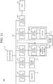
- FIG. 2 is a diagram of the control device 10.
- the control device 10 includes at least a control unit 101, a memory unit 103, a display unit 105, and a communication unit 107.
- the control unit 101 controls driving of each unit of the electric power control system 1.
- the control unit 101 includes a processor equipped with a calculation processing device exemplified by a CPU (Central Processing Unit) and memories exemplified by a ROM (Read On Memory) and a RAM (Random Access Memory).
- the control unit 101 monitors the driving status of each unit, the voltage value of the DC current in the first DC bus line 100, and the voltage value of the DC current in the second DC bus line 200, and controls each device.
- the control unit 101 can detect an abnormality in the voltage value of the first DC bus line 100 and the voltage value of the second DC bus line 200, respectively.
- a semiconductor memory such as a memory or an SSD (Solid State Drive)
- a magnetic recording medium (a magnetic tape, a magnetic disk, or the like), an optical recording medium, a magneto-optical recording medium, or a memory element that is a storage medium
- the memory unit 103 has a function of storing a control program and various kinds of information used in the control program.
- the display unit 105 displays control information under the control of the control unit 101.
- the display unit 105 may display the control information via a GUI (Graphical User Interface).
- GUI Graphic User Interface
- the display unit 105 may display the abnormality information in the display unit.
- the display unit 105 may not necessarily be arranged depending on the aspect of the control device 10.
- the communication unit 107 transmits and receives information to and from each device based on the control of the control unit 101.
- a notification unit that notifies an abnormality may be arranged in the control device 10 in addition to the control unit 101, the memory unit 103, the display unit 105, and the communication unit 107.
- a light or a buzzer may be used as the notification unit.
- FIG. 3 is a functional block diagram in the control unit 101.
- the control unit 101 includes an acquisition unit 1011, a determination unit 1013, and a drive instruction unit 1015 as a functional unit.
- the acquisition unit 1011 has a function of acquiring the voltage value of the DC current in the first DC bus line 100. In addition, the acquisition unit 1011 has a function of acquiring the voltage value of the DC current in the second DC bus line 200.
- the determination unit 1013 has a function of determining whether the voltage value of the DC current satisfies a predetermined condition (whether the voltage is higher than a reference voltage).
- the drive instruction unit 1015 has a function of instructing driving and termination of the water electrolysis device 41 and the fuel cell 51.
- FIG. 4 is a flowchart of the electric power control method.
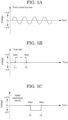
- FIG. 5A to FIG. 5C and FIG. 6A to FIG. 6B are schematic diagrams showing a relationship between time and voltage in the electric power control system 1.
- FIG. 5A is a schematic diagram showing a time variation of a voltage of the first DC bus line 100, and a schematic diagram showing a relationship between the time and a difference between the electric power from the solar power generation unit 20 of FIG. 1 and the electric power consumed by the load 90.
- the voltage of the first DC bus line 100 is constantly fluctuating.
- the control device 10 constantly acquires and monitors the voltage of the first DC bus line 100.
- control device 10 determines whether the acquired voltage satisfies a predetermined condition. Specifically, the control device 10 determines whether the acquired voltage of the first DC bus line 100 is higher than a reference voltage V 0 (step S103).
- FIG. 5B is a schematic diagram showing a relationship between a voltage fluctuation and time in the driving of the fuel cell 51.
- the voltage increases from a reference voltage V 0 by + ⁇ V.
- driving of the fuel cell 51 makes it possible to switch to a direction in which the voltage of the first DC bus line 100 in the electric power control system 1 is increased(replenishing the power).
- FIG. 5C is a schematic diagram showing a relationship between a voltage fluctuation and time in the driving of the water electrolysis device 41.
- the water electrolysis device 41 when the water electrolysis device 41 is driven in a range from time T3 to time T4, the voltage decreases from the reference voltage V 0 by - ⁇ V.
- driving the water electrolysis device 41 makes it possible to switch to a direction in which the voltage of the first DC bus line 100 in the electric power control system 1 is decreased (consuming power).
- FIG. 6A and FIG. 6B are schematic diagrams in which the relationship between the voltage of the first DC bus line 100 and the time shown in FIG. 5A is combined with the relationship between the driving of the fuel cell and the water electrolysis device and the time shown in FIG. 5B and FIG. 5C .
- the control device 10 switches driving and termination of the fuel cell 51 and the water electrolysis device 41 depending on the voltage of the first DC bus line 100. Specifically, in the case where the voltage of the first DC bus line 100 is higher than the reference voltage V 0 and the electric power is excessive, the water electrolysis device 41 is driven to generate hydrogen. Conversely, in the case where the voltage of the first DC bus line 100 is lower than the reference voltage V 0 and the electric power is insufficient, the fuel cell 51 is driven to supply the electric power.
- FIG. 6A a part where the voltage of the first DC bus line 100 is switched from the voltage higher than the reference voltage V 0 to the voltage lower than the reference voltage V 0 is surrounded by a dotted line, and the surrounded area is shown in an enlarged view in FIG. 6B .
- FIG. 6A a part where the voltage of the first DC bus line 100 is switched from the voltage higher than the reference voltage V 0 to the voltage lower than the reference voltage V 0 is surrounded by a dotted line, and the surrounded area is shown in an enlarged view in FIG. 6B .
- the control device 10 transmits a signal instructing termination of the water electrolysis device 41 and driving of the fuel cell 51 to the water electrolysis device 41 and the fuel cell 51 (step S107).
- the control device 10 transmits a signal instructing termination of the water electrolysis device 41 and driving of the fuel cell 51 to the water electrolysis device 41 and the fuel cell 51 (step S107).
- the control device 10 since it is desirable for the control device 10 to gradually change the voltage when driving or terminating the water electrolysis device and the fuel cell, there is a period during which the water electrolysis device 41 and the fuel cell 51 are simultaneously driven.
- the control device 10 transmits a signal instructing termination of the fuel cell 51 and driving of the water electrolysis device 41 to the water electrolysis device 41 and the fuel cell 51 (step S105). Also in this case, as in the case where the voltage of the first DC bus line 100 changes from the voltage higher than the reference voltage V 0 to the voltage lower than the reference voltage V 0 , if the electrochemical reaction inside the water electrolysis device 41 and the fuel cell 51 abruptly changes, there is a risk of breakage or a reduction in lifetime. Therefore, since it is desirable for the control device 10 to gradually change the voltage when driving or terminating the water electrolysis device and the fuel cell, a period of time occurs when the water electrolysis device 41 and the fuel cell 51 are simultaneously driven.
- control device 10 After transmitting each instruction signal to the water electrolysis device 41 and the fuel cell 51 (step S105, step S107), the control device 10 loops to a process of acquiring the voltage (voltage value) of the first DC bus line (step S101).
- FIG. 11 is a configuration diagram of a conventional electric power control system 500.
- the conventional electric power control system does not include the second DC bus line 200 as shown in FIG. 1 of the present application.
- the specification voltage value in the water electrolysis device and the fuel cell may be lower than the voltage value of the DC current flowing through the first DC bus line 100 by about 20 times or more.
- two converters namely, the DC/DC converter 110 and the DC/DC converter 43 are arranged between the first DC bus line 100 and the water electrolysis device 41.
- two converters, a DC/DC converter 111 and the DC/DC converter 53 are arranged between the first DC bus line 100 and the fuel cell 51.
- the electric power is supplied from the fuel cell 51 to the water electrolysis device 41 via the four DC/DC converters (the DC/DC converters 53, 111, 110, and 43).
- the DC/DC converters 53, 111, 110, and 43 the DC/DC converters 53, 111, 110, and 43.
- electric power loss occurs when the voltage is converted.
- the four DC/DC converters are required, the number of times the voltage was converted by the DC/DC converter reached four, resulting in significant power loss.
- the water electrolysis unit 40 and the fuel cell unit 50 are connected in parallel to the second DC bus line 200.
- the water electrolysis device 41 and the fuel cell 51 are simultaneously driven, when the electric power from the fuel cell flows to the water electrolysis device, the electric power passes through the second DC bus line 200 without passing through the first DC bus line 100.
- the number of times the voltage was converted by the DC/DC converter can be reduced to two, resulting in the reduction of the electric power loss.
- an electric power control system different from the first embodiment will be described. Specifically, an example in which a device other than the water electrolysis device 41 and the fuel cell 51 is connected to the second DC bus line will be described.
- FIG. 8 is an overall configuration diagram of an electric power control system 1A according to the present embodiment.
- the electric power control system 1A may include a storage battery unit 60 and a capacitor unit 70 in addition to the control device 10, the solar power generation unit 20, the storage battery unit 30, the water electrolysis unit 40, the fuel cell unit 50, the first DC bus line 100, the second DC bus line 200, the DC/DC converter 110, and the DC/AC converter 120, and the load 90.
- the storage battery unit 60 and the capacitor unit 70 are connected to the second DC bus line 200.
- the storage battery unit 60 includes a storage battery 61 and a DC/DC converter 63.
- the storage battery 61 stores electric power generated by the electric power control system 1A.
- the DC/DC converter 63 converts the voltage value of the DC current flowing through the second DC bus line 200 so as to match the specified voltage of the storage battery 61 in order to store the surplus electric power in the electric power control system 1A in the storage battery 61.
- the capacitor unit 70 includes a capacitor 71 and a DC/DC converter 73.
- the capacitor 71 stores electric power generated by the electric power control system 1A.
- the DC/DC converter 73 converts the voltage value of the DC current flowing through the second DC bus line 200 to match a specified voltage of the capacitor 71 in order to store the surplus power in the electric power control system 1A in the capacitor 71.
- the electric power control system 1A includes an electric power storage mechanism for storing electric power, such as the storage battery 61 and the capacitor 71 connected to the second DC bus line 200.
- an electric power storage mechanism for storing electric power such as the storage battery 61 and the capacitor 71 connected to the second DC bus line 200.
- the DC/AC converter is connected to the second DC bus line 200, and a method of supplying electric power to a load will be described.
- FIG. 9 is an overall configuration diagram of an electric power control system 1B according to the present embodiment.
- the electric power control system 1B may include a DC/AC converter 210 in addition to the control device 10, the solar power generation unit 20, the storage battery unit 30, the water electrolysis unit 40, the fuel cell unit 50, the first DC bus line 100, the second DC bus line 200, the DC/DC converter 110, the DC/AC converter 120, the load 90, the storage battery unit 60, and the capacitor unit 70.
- the DC/AC converter 210 may be connected to the second DC bus line 200.
- the DC/AC converter 210 converts the DC current flowing through the second DC bus line 200 into an AC current, and supplies the AC current to the load 90.
- FIG. 10 is a flowchart of the electric power control method.
- the control device 10 acquires the voltage value of the first DC bus line 100 (step S201).
- the control device 10 constantly acquires and monitors the voltage value (power value).
- the control device 10 determines whether the voltage of the first DC bus line satisfies the predetermined condition (step S203). Specifically, the presence or absence of an abnormality in the electric power control system 1B is determined.
- the abnormality in this case includes an emergency such as a momentary low voltage or a power failure.
- step S203 the control device 10 instructs the supply of electrical power to the load 90 via the DC/AC converter 120 (also referred to as a first DC/AC converter) (step S205).
- the DC/AC converter 120 also referred to as a first DC/AC converter
- step S203 If an abnormality is detected (step S203; Yes), the control device 10 instructs the supply of electrical power to the load 90 via the DC/AC converter 210 (also referred to as a second DC/AC converter) (step S207).
- the DC/AC converter 210 also referred to as a second DC/AC converter
- the second DC bus line can be used as an emergency power source, and stable power can be supplied in an emergency.
- the electric power control system includes the solar power generation unit
- the present invention is not limited to this.
- a unit having an electric power generation mechanism that uses wind, geothermal, biomass, hydroelectric, temperature differential, or other renewable energy may be used or a combination of these electric power generation mechanisms may be used, as appropriate.
- the present invention is not limited to this.
- an engine such as an internal combustion engine or an external combustion engine may be used as the power generation apparatus.
- V 0 reference voltage
- the reference voltage of the power generation apparatus (fuel cell) and the power generation fuel generation apparatus (water electrolysis device) may have different values. In this case, it is possible to reduce the number of unnecessary start-stop operations due to small voltage fluctuations.
Landscapes
- Engineering & Computer Science (AREA)
- Power Engineering (AREA)
- Fuel Cell (AREA)
- Electrolytic Production Of Non-Metals, Compounds, Apparatuses Therefor (AREA)
Applications Claiming Priority (2)
| Application Number | Priority Date | Filing Date | Title |
|---|---|---|---|
| JP2022127416 | 2022-08-09 | ||
| PCT/JP2023/016197 WO2024034194A1 (ja) | 2022-08-09 | 2023-04-25 | 電力制御システム |
Publications (2)
| Publication Number | Publication Date |
|---|---|
| EP4572070A1 true EP4572070A1 (de) | 2025-06-18 |
| EP4572070A4 EP4572070A4 (de) | 2025-12-10 |
Family
ID=89851480
Family Applications (1)
| Application Number | Title | Priority Date | Filing Date |
|---|---|---|---|
| EP23852180.1A Pending EP4572070A4 (de) | 2022-08-09 | 2023-04-25 | Leistungssteuerungssystem |
Country Status (5)
| Country | Link |
|---|---|
| US (1) | US20250167559A1 (de) |
| EP (1) | EP4572070A4 (de) |
| JP (1) | JP7796882B2 (de) |
| CN (1) | CN119563267A (de) |
| WO (1) | WO2024034194A1 (de) |
Family Cites Families (11)
| Publication number | Priority date | Publication date | Assignee | Title |
|---|---|---|---|---|
| US7622888B2 (en) * | 2005-12-13 | 2009-11-24 | Lockheed Martin Corporation | Fuel cell-electrolyzer system controlled by a single bi-directional DC-to-DC converter |
| JP5308268B2 (ja) * | 2009-08-05 | 2013-10-09 | 本田技研工業株式会社 | 電力供給システム |
| US8970176B2 (en) * | 2010-11-15 | 2015-03-03 | Bloom Energy Corporation | DC micro-grid |
| WO2015105006A1 (ja) * | 2014-01-08 | 2015-07-16 | ソニー株式会社 | 電力制御装置及び電力制御方法 |
| JP5841279B2 (ja) * | 2014-05-16 | 2016-01-13 | 米沢電気工事株式会社 | 電力充電供給装置 |
| CN106160022A (zh) * | 2015-03-31 | 2016-11-23 | 积能环保电机工程科技有限公司 | 直流多电压输配电系统 |
| WO2019103059A1 (ja) | 2017-11-21 | 2019-05-31 | 国立研究開発法人理化学研究所 | 直流バス制御システム |
| CN211790787U (zh) * | 2020-03-17 | 2020-10-27 | 珠海格力电器股份有限公司 | 一种应用燃料电池的直流微网系统 |
| WO2021192107A1 (ja) * | 2020-03-25 | 2021-09-30 | Tdk株式会社 | 給電システム、及び電力管理装置 |
| WO2021261094A1 (ja) * | 2020-06-22 | 2021-12-30 | 国立研究開発法人理化学研究所 | 直流バス制御システム |
| JP7585781B2 (ja) | 2020-12-25 | 2024-11-19 | オムロン株式会社 | 発電システム、制御方法およびプログラム |
-
2023
- 2023-04-25 WO PCT/JP2023/016197 patent/WO2024034194A1/ja not_active Ceased
- 2023-04-25 CN CN202380053624.7A patent/CN119563267A/zh active Pending
- 2023-04-25 EP EP23852180.1A patent/EP4572070A4/de active Pending
- 2023-04-25 JP JP2024540263A patent/JP7796882B2/ja active Active
-
2025
- 2025-01-22 US US19/033,801 patent/US20250167559A1/en active Pending
Also Published As
| Publication number | Publication date |
|---|---|
| JP7796882B2 (ja) | 2026-01-09 |
| WO2024034194A1 (ja) | 2024-02-15 |
| US20250167559A1 (en) | 2025-05-22 |
| EP4572070A4 (de) | 2025-12-10 |
| CN119563267A (zh) | 2025-03-04 |
| JPWO2024034194A1 (de) | 2024-02-15 |
Similar Documents
| Publication | Publication Date | Title |
|---|---|---|
| EP2715904B1 (de) | System und verfahren für die integration und verwaltung von nachfragen/reaktionen zwischen alternativen energiequellen, netzleistungen und lasten | |
| US8860252B2 (en) | Power storage system, method of controlling the same, and computer readable recording medium storing a program for executing the method | |
| CN102270884B (zh) | 储能系统及其控制方法 | |
| US20090189445A1 (en) | Renewable energy management and storage system | |
| US8253271B2 (en) | Home power supply system | |
| KR102046045B1 (ko) | 재생에너지 저장 시스템 및 그 동작 방법 | |
| US20110121648A1 (en) | Power Supply System Including Alternative Sources | |
| US9846418B2 (en) | Energy control system, energy control device, and energy control method for prioritizing a power generation source based on the possibility of selling generated power | |
| WO2021261094A1 (ja) | 直流バス制御システム | |
| EP4239823A1 (de) | Elektrolysatorleistungsumwandlung | |
| Tephiruk et al. | Hybrid energy storage system to enhance efficiency of renewable energy usage | |
| JP4202371B2 (ja) | 電力供給システム、集合住宅、及びプログラム | |
| JP2007066724A (ja) | 燃料電池発電システム | |
| JP2015220889A (ja) | 電力供給システム | |
| KR20150085227A (ko) | 에너지 저장 시스템 및 그의 제어 방법 | |
| KR101020200B1 (ko) | 연료전지의 전력 제어방법 및 그의 연료전지시스템 | |
| EP4572070A1 (de) | Leistungssteuerungssystem | |
| JP2003153448A (ja) | 発電システム | |
| JP4624717B2 (ja) | 電源システム | |
| JP5820984B2 (ja) | 配電システム | |
| JP2026053552A (ja) | 電力制御方法 | |
| KR102573283B1 (ko) | 염분차발전용 전력변환 시스템 | |
| EP2869429B1 (de) | Batteriespeichersystem und steuerungsverfahren dafür | |
| KR20120080018A (ko) | 연료전지를 이용한 발전 시스템 | |
| KR102046821B1 (ko) | 솔라셀을 이용한 발전 시스템의 발전 전압에 따른 전력 분배 및 송전 제어 장치 |
Legal Events
| Date | Code | Title | Description |
|---|---|---|---|
| STAA | Information on the status of an ep patent application or granted ep patent |
Free format text: STATUS: THE INTERNATIONAL PUBLICATION HAS BEEN MADE |
|
| PUAI | Public reference made under article 153(3) epc to a published international application that has entered the european phase |
Free format text: ORIGINAL CODE: 0009012 |
|
| STAA | Information on the status of an ep patent application or granted ep patent |
Free format text: STATUS: REQUEST FOR EXAMINATION WAS MADE |
|
| 17P | Request for examination filed |
Effective date: 20250123 |
|
| AK | Designated contracting states |
Kind code of ref document: A1 Designated state(s): AL AT BE BG CH CY CZ DE DK EE ES FI FR GB GR HR HU IE IS IT LI LT LU LV MC ME MK MT NL NO PL PT RO RS SE SI SK SM TR |
|
| REG | Reference to a national code |
Ref country code: DE Ref legal event code: R079 Free format text: PREVIOUS MAIN CLASS: H02J0003380000 Ipc: H02J0001080000 |
|
| DAV | Request for validation of the european patent (deleted) | ||
| DAX | Request for extension of the european patent (deleted) | ||
| A4 | Supplementary search report drawn up and despatched |
Effective date: 20251111 |
|
| RIC1 | Information provided on ipc code assigned before grant |
Ipc: H02J 1/08 20060101AFI20251105BHEP Ipc: H02J 3/32 20060101ALI20251105BHEP Ipc: H02J 15/00 20060101ALI20251105BHEP Ipc: H02J 3/38 20060101ALI20251105BHEP Ipc: H02J 1/10 20060101ALI20251105BHEP |
|
| RAP3 | Party data changed (applicant data changed or rights of an application transferred) |
Owner name: FUJITA CORPORATION |